Implementation of Fractal image compression on FPGA Thai Nam Son1, Ong Manh Hung1, Dang Thi Xuan2, Tran Van Long2, Nguyen Tien Dzung2, Thang Manh Hoang2 1
Television Advertising and Services Center, Vietnam National Television
2
School of Electronics and Telecommunications, Hanoi University or Science and Technology, Vietnam Email: 1
[email protected],
[email protected],
[email protected],
[email protected]
Abstract – Fractal Image Compression (FIC) is known as a lossy technique, which requires a large amount of operations to complete the codification. The development of VLSI technology allows the creation of complete systems inside a single chip likely FPGA, therefore the number of required operations may reduce and data compression becomes increasingly significant for storage and transmission. In this paper, we propose the implementation of a FIC framework on Xilinx Virtex 5 (XUPV5-LX110T) FPGA board, which allows to significantly decrease the elapsing time compared to that implemented in DSP at the same clock rate of 100MHz. The experimental results performed by Fisher’s method for a gray level image have verified the possibility to design a SoC for fast fractal coder/decoder with an increased compression performance. Keywords- FIC, SoC, FPGA, Fisher’s method.
I.
In our previous work [7], we have implemented FIC on DSP TMS320C5515 kit to test the possibility of successfully coding and decoding without memory overflow using 64 × 64 images. In this paper, we propose a FIC implementation of speed-up Fisher’s method on Xilinx Virtex 5 (XUPV5LX110T) FPGA board and compare its performance with that implemented in DSP board in terms of elapsing time and number of iterations at the same clock rate of 100MHz. The experimental results showed that FIC algorithms can be realized in SoC for images and also applied to fractal video compression. The paper is organized in four sections. Following the introduction in Section 1, the summary of theory of FIC will be described in Session 2. Section 3 presents the proposed FIC implementation scheme on Xilinx FPGA board. Finally, Section 4 discusses about experimental results and performance evaluation followed by the conclusion of the paper.
INTRODUCTION
Fractal image compression (FIC) is based on partitioned iterated function system (PIFS) which uses the self-similarity feature of image to compress images [1]. In fractal image compression, an image is partitioned into a set of nonoverlapping blocks called ranges. Another set of larger blocks called domains is used to find the best region in each range, which is most similar to it [2]. Because we have to search the best match domains for each range and compute the transformation of the corresponding mapping, it takes a long time to compress the image. However, FIC is a competitive technique for improved performance in terms of the transmitted image representation and faster decompression because of asynchronous features in its algorithm [1][2][3]. In addition, FIC implementation may be speed up by utilization of parallelizable operations. Therefore, several research approaches have focused on FIC speed-up algorithms to reduce the coding time and improve decoding time to exploit great properties of FIC, for example independence in free decompressed resolution with less distortion. These approaches may be divided into three main approaches: 1) classification approach like Fisher’s [1] or Hurtgen’s method [4]; 2) feature vector approach like Saupe’s method [5] or Mass Center method [2]; 3) both of the two methods mentioned above like Saupe-Fisher method or Saupe-Mass Center method [2] to decrease the number of comparisons that takes a long time to be computed and compared.
978-1-4673-2493-9/12/$31.00 ©2012 IEEE
II.
THEORY OF FRACTAL IMAGE COMPRESSION
A. Fractal Image Compression In fractal image compression, an image is partitioned into a set R of n non-overlappig square range bloks. Another set D of 2 n × 2n largersquare domain block is subsampled by pixel averaging to have the same size as the ranges.
For each Ri ∈ R , this compression method searches through all of D Dto find a Di ∈ D most looks like the range Ri . It also find the best contrast and brightness setting
si and oi for the
transformation wi of the mapping from Di into Ri :
⎡ x ⎤ ⎡ai bi ⎤ wi ⎢ y ⎥ = ⎢ ci di ⎥ ⎢z⎥ ⎢ 0 0 ⎥ ⎣ ⎦ ⎣ ⎦
(1)
si controls the contrast and oi controls the brightness of the transformation, z is the gray level of a pixel at position ( x, y ) [1]. where
Therefore, for each Di ∈ D ,
si and oi using least square
regression are calculated and the Di with the least rms
339
difference is picked [1]. A set of all wi called W , is the transformation of the encoding image. The image f that
each of which there are 24 different possible orders of the variances that define 24 subclasses [1][2].
satisfies f = W ( f ) is the fixed point of W . If W is contractive, f is unique and an approximation of the original image, therefore the decoding process is based on this property.
Major class 1: A1 > A2 > A3 > A4
(2)
Major class 2: A1 > A2 > A4 > A3
(3)
Since the size of R is very large, the number of comparison is very large, too. Hence, the way to partition image is very important in Fractal Image Compression to reduce this size but still keep the quality of decoding image. There are many ways to partition image to cover the image well. In this paper, we use quadtree partition. In a quadtree partition, a square larger than the minimum size in the image is broken up into four equal-sized sub-squares when its entropy is greater than the entropy threshold or there is no domain to satisfy the rms error tolerance [1].
Major class 3: A1 > A4 > A2 > A3
(4)
After all ranges are covered, we do not store all the coefficients in (1). The contrast coefficient si and the
oi are quantized and stored in a fixed number of bits. In this paper, we use 4 bits to store si and 7 bits to store oi . Instead of storing the other coefficients, we store brightness coefficients
the positions of Ri , both the positions and size of Di and the orientation involving the rotation and flip information [1]. The decoded image is created by iterating W from an initial image. For each Ri , Di unpacked from the compressed file, domain Di is sub-sampled by averaging each
(
)
In Hurtgen Scheme, the square block is also partitioned into four quadrants and their average pixel values and variances are calculated. Each quadrant is assigned with a bit which is “1” if the average of pixel value is larger than the overall mean and “0” otherwise [2]. Therefore, we have 15 major classes from “0000” to “1110” because the class “1111” is impossible to be appeared. Each major class is then divided into 24 subclasses utilizing the variances in the similar way as that in the Fisher scheme. Finally, we have 360 classes in all. III.
IMPLEMENTATION OF FIC ON XILINX FPGA
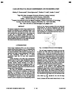
A. Features of Xilinx Virtex 5 (XUPV5-LX110T) The XUPV505-LX110T Xillinx FPGA board is a featurerich general purpose evaluation and development platform with on-board memory and industry standard connectivity interfaces. It features the Virtex-5 XC5VLX110T device. The XUPV5-LX110T is a unified platform for teaching and research in disciplines such as digital design, embedded systems, digital signal, image and video processing and communications etc. As depicted in Figure 1, the XUPV5LX110T Development System has the following features:
-
Xilinx Virtex-5 XC5VLX110T FPGA
non-overlapping 2 × 2 square sub-block. Then, each pixel value in subsampled domain is multiplied by si , added to oi ,
-
Two Xilinx XCF32P Platform Flash PROMs (32 Mbyte each) for storing large device configurations
and placed in the location in the corresponding range Ri determined by the orientation. This process is repeated until the decoding image is fixed (i.e. the fixed point f is approximated).
-
Xilinx SystemACE Compact Flash configuration controller
-
64-bit wide 256Mbyte DDR2 small outline DIMM (SODIMM) module compatible with EDK supported IP and software drivers
B. The Speed-up Methods in Fractal Image Coding Since the number of comparisons is very large, the encoding time is very long. To reduce this time, several methods have been proposed so far. These methods base on classification approach or feature vector approach or both of them [1][2][4][5]. Due to two later approaches require a huge memory to run; we only implement the methods based on classification approach which includes Fisher and Hurtgen schemes. In these methods, for each range, we only find the best-match domain in the same classification. Therefore, the number of comparisons is significantly decreased.
In The Fisher scheme, a square block is decomposed into four quadrants. We compute the average pixel values Ai and the variances Vi of each quadrant for i = 1 ÷ 4 . There are three possible orientations depending on the average of pixel values. This divides the set of domains into three major classes, for
Figure 1. Xilinx Virtex 5 (XUPV5-LX110T) board
-
On-board 32-bit ZBT synchronous SRAM and Intel P30 StrataFlash
-
10/100/1000 tri-speed Ethernet PHY supporting MII, GMII, RGMII, and SGMII interfaces
340
-
USB host and peripheral controllers
-
Programmable system clock generator
-
Stereo AC97 codec with line in, line out, headphone, microphone, and SPDIF digital audio jacks
-
RS-232 port, 16x2 character LCD, and many other I/O devices and ports
B. Blockdiagram of FPGA implementation
The SYSACE is the interface between the processor local bus (PLB) and microprocessor interface (MPU) of the system ACE compact flash solution peripheral. The TIMER is used calculate time compress and decompress fractal image. The UART lite interface connects to the PLB and provides the controller interface for asynchronous serial data transfer. TABLE I. COMPARE TMS320C5515 DSP WITH SOC IS BUILD ON VIRTEX5 Feature Clock rate Block Ram Bus read data Bus address Bus peripheral interface
TMS320C5515 100MHz 256KB 32 bit 32 bit 16 bit
SoC (System on Chip) Virtex 5 100MHz 256KB 32 bit 32 bit 32 bit
C. FIC Implementation Process 1) Sorfware specification Table II lists software packages and their features, which are used for implementation of FIC on a Virtex 5 (XUPV5LX110T) FPGA board. Figure 2. SoC architecture used for implementation of FIC
Figure 2 shows the SoC architecture used for implementation of FIC in a Virtex 5 (XUPV5-LX110T) FPGA evaluation board. The clock rate of SoC is set to 100MHz. The architecture consists of a MicroBlaze embedded processor soft core, a loacal memory unit, a memory control core (MPMC), a SYSACE core, a GPIO core, a UART core, and a timer (TIMER) core. The MicroBlaze embedded processor soft is a reduced instruction set computer (RISC) optimized for implementation in Xilinx Field Programmable Gate Arrays (FPGAs). This processor is highly configurable which allows us to select a specific set of features required by you design. It has the following features: -
32 32-bit general purpose registers.
-
32 bit instruction word with three operands and two addressing modes
-
32 bit address bus
-
Single issue pipeline
The Local Memory is a simple memory module used as ROM and RAM of the system with the total size of 16KByte. Xilinx BRAM is a memory module during FPGA implementation. The GPIO has two 32-bit registers to control Port Pins. There are 4 byte-size register for PORT Output and 4 byte-size registers for an input. The GPIO control the TFT LCD to display an image once it has decoded. The MPMC is a fully parameterizable memory controller the supports SDRAM/DDR/DDR2/DDR3/ LPDDR memory.
TABLE II. SOFTWARE PACKAGES USED IN IMPLEMENTATION No
Software Xilinx platform studio version 12.4 (XPS)
1
Xilinx software development kit 12.4 (SDK) 2
Function - XPS is used primarily for mbedded processor hardware system development. - Configuration of the icroprocessor, peripherals, and the interconnection of these components, along with their respective property assignments, takes place in XPS - SDK is the recommended software development environment for simple and complexsoftware applications. While basic software development can be accomplished within XPS, this capability will be removed in a future release.
Version
12.4
12.4
2) Implementation precedure Figure 3 describes the detailed steps to implement FIC on FPGA board. a) Stage 1: Creating the microblaze and the peripherals First of all, the microblaze and peripherals are created by utilizing the XPS tool to oprate at clock rate set to 100MHz. The microblaze is then configured to optimize the calculation and control of the system memory. After synthesis stage, the library for microblaze and the peripherals is generated as a .bit file for FPGA configuration and it is used finally for configuring the FPGA core and storing the specification parameters regarding to the peripherals for connection to microblaze. b) Stage 2: Creating software for the microblaze SDK tool is used to create software for the microblaze. SDK tool reads .c file and peripheral’s specification file and then compiles them to create .elf file.
341
Figure 3. FIC implementation process
c) Stage 3: Observation of the results IMPACT tool which is integrated in SDK is used to download the .bit and .elf files to the FPGA board and the results may be observed by the terminal equipment connected to the system. 3) Resource Table III shows the utilization of the system resource, wherein one can see the number of slice LUTs required to fulfill the implementation is only about 2% over those available. TABLE III. SYSTEM RESOURCES USED IN IMPLEMENTATION
Table IV shows the use of domain pool of type D2 at different sizes varied from 2 × 2 to 16 × 16 and the corresponding number of domains, which is estimated correspondingly. As shown in Table IV, when the number of searching class is changed, the highest PSNR for the decompressed image can be achieved utilizing the maximum class number of 72 for searching whole domain pool, while the elapsing time remains almost unchanged. This comes from the parallelization in the Fisher’s algorithm to be implemented on the FPGA. TABLE IV. DOMAIN POOL WITH DIFFERENT RANGE SIZE AND NUMBER OF DOMAIN Domain pool
Slice logic utilization
Used
Available
Utilization
Number of slice register
1911
69120
2%
Number of slice LUTs
2120
69120
2%
Number of Block RAM/FIFO
64
148
43%
Number of DSP48Es
3
64
4%
IV.
EXPERIMENTAL RESULTS AND PERFORMANCE EVALUATION In order to evaluate the performance of the proposed implementation, we use an 8-bit Lena image with size of 64 × 64 in the experiments. With larger size of image, SRAM controller interface is added so as to the system work normally. Because block RAM of SoC only store domain and range with size of 64x64. In the FPGA implementation, the sizes of quadtree scheme and domain pool in Fisher’s method is varied, and some parameters such as the elapsing time required for coding, PSNR, compression ratio, the number of iterations in decoding process are then recorded and monitored, respectively. Following the approach in [1], the domain pool of type D2 is utilized and classified according to Fisher’s parameters. That is the larger size of domain block is the fewer number of the domains. For performance comparison, the similar process is performed on the TMS320C5515 DSP board at the same clock rate of 100MHz, which is designed by Texas Instrument using C/C++ libraries supported by Texas Instrument [8].
D2
Size
Number of domains
2×2
256
4×4
225
8×8
169
16 × 16
81
TABLE V. PERFORMANCE COMPARISON BETWEEN FPGA BASED AND DSP BASED IMPLEMENTATION OF FISHER’S METHOD Results Board Number of Encoding time PSNR classes (s) (dB)
DSP
FPGA
1
13.000
21.746
3
14.000
22.402
24
25.000
23.769
72
47.000
24.117
1
11.025
11.830
3
11.033
11.830
24
11.038
12.310
72
11.058
22.280
Table V demonstrates the encoding time versus PSNR of the FIC speed-up Fisher’s method implemented on FPGA and DSP boards for different number of classes. The data have been performed for the set of parameters described as follow: entropy threshold ET = 6, rms error tolerance RET = 16, minimum rang size MiS = 4, maximum range size MaS = 16,
342
number of iteration NI = 20, and domain pool D2 as depicted in Table IV. For the FPGA based implementation, when the number of class (NC) is varied, the encoding time remains almost unchanged while PSNR improves significant, since the full search has been performed in the given domain as well as the parallelization of the Fisher’s algorithm. The test for comparison is also carried out in decompression for different NI. The results on FPGA shows PSNR improvement for increased number of iteration while elapsing time remains is almost unchanged. Meanwhile, the DSP based implementation requires quite longer time to complete encoding. Therefore, we believe that FPGA is an efficient SoC for implementation because of superior performance on FPGA over that of DSP, even thought the PSNR obtained on DSP somewhat better for RET = 6.
(a)
(b)
(c)
Domains and ranges comprarision process is operated from the small size domain area to the large size domain area. Domains and ranges are stored in block RAM of SoC (System on Chip), the encoding time is not much influenced by the reading and writing time. When the compression ratio is high, the number of comparisions to find the best domain is also small. Therefore, the encoding time is nearly constant and only depends on the limitation of speed of SoC. For subjective performance evaluation, the decompressed and original Lena images with the setting parameters are demonstrated in Figure 4 for different NC.
(d)
(e)
(f)
Figure 4: Original and decompressed Lena images for ET = 6, RET = 6, MiS = 4, MaS = 16, NI = 20. (a) NC = 1, (b) NC = 3, (c) NC = 24, (d) NC = 72, (e) Decompressed image on DSP with NC =72, (f) Original image
(a)
(b)
(c)
(d)
(e)
Figure 5. Original and decompressed Lena images for ET = 6, RET = 20, MiS = 4, MaS = 16, NI = 20 (a) NC = 1, (b) NC = 3, (c) NC = 24, (d) NC = 72, (e) Original image
TABLE VI. RESULTS OF FISHER'S METHOD WITH RET = 20 Results Method Number of Encoding time PSNR classes (s) (dB)
Fisher
1
11.017
19.5
3
11.023
19.54
24
11.040
20.26
72
11.052
26.35
The experiment on FPGA implementation is repeated where RET value is set to 20. The performance in terms of PSNR and encoding time are shown in Table VI. Again, one can see the elapsing time varies around 11 seconds with NC = 72, however the PSNR is much better compared to that in case
NC = 6. In the similar manner of Figure 4, the original and decompressed Lena images for RET = 20 are represented in Figure 5. It means that the increment of RET may lead to improvement of decompression quality. V.
CONCLUSION
In this paper, an implementation of fractal image compression with speed-up Fisher's method has been realized in Xilinx Virtex 5 (XUPV5-LX110T) FPGA board. The analysis of the experimental results shows that the encoding time implemented in FPGA is much superior over that in DSP, while improving the compression quality. The successful implementation of FIC on FPGA is expected to resolve heavy computation time and then exploit the advantages of FIC such as high compression ratio at high compression ratio, fast
343
decoding time and so on. With an increasing demand for high quality in coder/decoder techniques, the proposed approach may be further developed to apply for fractal coding for color images as well as video sequences using high performance FPGA. REFERENCES Y. Fisher, “Fractal Image Comppression - Theory and Application”, NewYork: Springer-Verlag, 1995. [2] Mario Polvere and Michele Nappi,“Speed-Up In Fractal Image Coding: Comparison of Methods”, IEEE Transactions on Image Processing, Vol. 9, No. 6, 2000, pp. 1002-1009. [3] A. Selim, M. M. Hadhoud, M. I. Dessouky and F. E. Abd ElSamie,ERTU,Egypt, A Simplified Fractal Image Compression Algorithm in Computer Engineering & Systems, 2008. ICCES 2008, International Conference, pp. 53 – 58, 25-27 Nov. 2008, online published in IEEExplorer. [1]
B. Hurtgen and C. Stiller, “Fast hierarchical codebook search for fractal coding of still images,” in Proc. EOS/SPIE Visual Communications PACS Medical Applications ’93, Berlin, Germany, 1993. [5] D. Saupe, “Fractal image compression by multi-dimensional nearest neighbor search,” in Proc. DCC’95 Data Compression Conf., Mar. 1995. [6] Spectrum Digital, Inc., “TMS320C5515 eZdspTM USB Stick Technical Reference”, 512845-0001, RevA, Febuary 2010. [7] Duong Phu Thai, Nguyen Tien Dzung, Thang Manh Hoang, de Souza-Daw. T, "Implementation of fractal image encoding/decoding on DSP,” in Proc. of Joint 3rd Int’l Conference Workshop on Nonlinear Dynamics and Synchronization and Sixteenth International Symposium on Theoretical Electrical Engineering (INDS&ISTET 2011), pp. 16, July 25-27, 2011, online published in IEEExplorer [4]
[8]
Texas Instrument, “TMS320C55xx Optimizing C/C++ Compiler User’s Guide, August 2010.
344