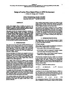
CAS-34, NO. 4, APRIL 1987. O) +Z--~ imaginary. Fig. 1. (a) hrallel connection of complex filters, and (b) equivalent filter obtained by taking real part of output.
345
IEEE TRANSACTIONS ON CIRCUITS AND SYSTEMS, VOL. CAS-34, NO. 4, APRIL 1987
Implementation’ of Real Coefficient Digital Filters Using Complex Arithmetic PHILLIP A. REGALIA,
STUDENT MEMBER, IEEE, SANJIT AND JALIL FADAVI-ARDEKANI
Abstract -Complex coefficient digital filters, with applications for processing real sequences, are examined. The method is quite general, and allows any real rational transfer function to be expressed in terms of a complex rational transfer function of reduced order. When implemented in complex hardware form, the reduction of filter order can provide an increase in computational efficiency and speed. Conventional filter structures, such as parallel, cascade, lattice, and state-space forms, are extended to the complex domain. Illustrative examples of complex coefficient filter synthesis are included, along with coefficient sensitivity comparisons between the complex coefficient filters and their real coefficient counterparts.
I. INTRODUCTION IGITAL FILTERING involves the processing of an input sequence{ u(n)} to generatean output sequence {r(n)} with more desirable properties. In most applications, one is concerned with real input and output sequences, and thus, the digital filter of interest is characterized by a real impulse responsesequence{h(n)} or, equivalently, by a transfer function H(z) with real coefficients. In this paper, we consider a generalization of the above real coefficient digital filters to filters characterized by a complex impulse responsesequence,i.e., transfer functions with complex coefficients. The concept of complex coefficient digital filters, to be called simply the complexfilters, is not new [l]-[8]. However, all of this earlier work appears to be directed towards the processing of complex input sequences.Crystal and Ehrman [l] have outlined methods of converting a real coefficient filter into a complex filter with an unsymmetrical frequency responseand mentioned its potential use in the processing of analytic signals and complex envelopes. Boite and Leich [2] have discussed approximation techniques for complex coefficient filters, which they see as,natural candidates for processingdigital analytic signals. Boite [3] has also considered the implementation of complex digital filters using a parallel connection of first-order complex sections. Several other
D
Manuscript received April 22, 1986; revised October 16, 1986. This work was supported in part by the National Science Foundation under Grant ECS 85-08017 and in part by a University of California MICRO grant with matching supporttfunds from the Intel Corporation and the Rockwell Corporation. P. A. Regalia and S. K. Mitra are with the Signal Processing Laboratory, Department of Electrical and Computer Engineering, University of California, Santa Barbara, CA 93106. J. Fadavi-Ardekani is with AT&T Bell Laboratories, Allentown, PA 18103. IEEE Log Number 8612929
K. MITRA,
FELLOW, IEEE,
authors have also indicated the need and applications of such filters [4]-[7]. Fettweis [8] has shown the development of complex wave digital filters from complex analog reference filters and suggestedtheir use in the processing of complex signals. Here, we investigate the use of complex digital filters in the processing of real sequences,as complex arithmetic may afford potential benefits in real filtering applications. For example, any real coefficient transfer function can be expressed in terms of a complex transfer function of typically reduced order, which may allow for increased computational speed in a practical implementation. In fact, in some cases,the complex structure can be shown to lead to a more computationally efficient implementation [9]. It is of interest, then, to compare the behavior of complex coefficient filters to their real coefficient counterparts. In Section II, we outline a simple method of determining the filter transfer function meeting the prescribed specifications, Section III sketches various methods of realization, and Section V presents simulation examples with coefficient sensitivity comparisons. II.
THE BASIC CONCEPTS
A. Definitions and Notations A complex coefficient transfer function will be denoted with a bold-face capital letter with its coefficients written in Greek lower caseletters as shown below A(z) G(z)=~(z)=
cw,+a,z-‘+ 1+&z-‘+
*** +a,z+ *** -t/3MZYM
(1)
to distinguish it from the more conventional real coefficient transfer function H(z) given as A(z) Ho=B(r)=
a, + alzP1 + . . . + aNzPN l+b,z-‘+ ... +b,z-N *
(2)
The complex coefficient transfer function whose coefficients are the complex conjugatesof those of G(z) will be denoted by G,(z). B. Developmentof Complex Coefficient Transfer Function Let H(z) be the real coefficient transfer function meeting the prescribed specifications. A partial-fraction expansion of H(z), assuming simple poles without any loss of
0098-4094/87/0400-0345$01.00 01987 IEEE
IEEE TRANSACTIONS ON CIRCUITS AND SYSTEMS, VOL. CAS-34, NO. 4, APRIL 1987
346
O)+Z--~ imaginary
Fig. 1.
(a) hrallel connection of complex filters, and (b) equivalent filter obtained by taking real part of output.
generality, is of the form H(z)
=d+
5
Pi
i=l ‘-!Yi
I y
ui
I y
i=l z-Ai
ut
i=l z-A:
where N, and NC are the number of real poles ti’s and complex poles Xi’s, respectively,with residuespi’s and ui’s. We can thus decomposeH(z) as H(z) =1/2[G(z)+ where G(z)=d+
’
5 pi+ i=l z-Si
G.(z)]
Fig. 2.
(3)
Complex filter building blocks.
0)
(4 y(n) +
NJ2 2Vi C i=l z-xi.
(5)
It should be noted that the decomposition of a real coefficient transfer function into a sum of two complex coefficient transfer functions as given by (4) is not unique. For example, in G(z) of (5), we can replace the real constant d by a complex constant d + iS with 6 being arbitrary, while replacing the corresponding constant in G,(z) by d - jS. There is also an additional flexibility in the assignment of complex poles of H(z) to G(z). For example, either the pole at z = Ai or its complex conjugate at z = h’i can be assignedto G(z) leading to various other possible expressions for the complex coefficient transfer function. Additional approachesto obtaining the decomposition of H(z) in the form of (4) are outlined in Section III.
Fig. 3. Parallel-form realization.
complex multipliers as shown in Fig. 2, where the solid line and the dotted line indicate, respectively, the real and imaginary parts of a complex signal variable. Thus, if u(n) denotes a complex signal variable with real and imaginary parts, r(n) and x(n) u(n) =r(n)+jx(n)
(6)
at the input of a complex unit delay, its output will be u(n-l)=r(n-l)+jx(n-1).
(7) The operations of the complex adder and the complex multiplier are quite similar to their real counterparts. Thus, C. Basic Implementation Scheme if the inputs to a complex adder are q(n) = r,(n) + jx,(n) An implementation of H(z) ‘is thus simply a parallel and u2(n) = r2(n)+ j,,(n), respectively, its output u,,(n) connection of two complex filters characterizedby transfer is given by functions G(z) and G.(z), respectively, as shown in Fig. (8) b(n) = [rl(n)+ r,(n)] + j[xl(n)+ x2(n)]. l(a). However, for a real input u(n), the output of G(z) is the complex conjugate of that of G,(z). As a result, the Likewise, the output u,,(n) of a complex multiplier with real part of the complex output from G(z) is the desired a multiplier coefficient I = E + jF for an input u(n) k real sequencey(n) indicating that a single complex filter is r(n)+ jx(n) is given by sufficient for processing u(n) (seeFig. l(b)). Note that the order of G(z) is N, + N,/2, whereasthe order of H(z) is u,,(n) = [Ear(n)- F-x(n)] + j[E.x(n)+ F-r(n)]. (9) N,, + NC.If all poles of H(z) are complex, as is usually the case, the order of G(z) is half that of H(z). C. Parallel Forms Just as in the caseof a real filter [lo], there are two basic III. REALIZATION METHODS parallel realizations of a complex filter. One of the realizaA. Building Blocks tions follows directly from the partial-fraction expansion The basic building blocks required in the case of com- form of (5) and is shown in Fig. 3. A second basic plex filters are complex unit delays, complex adders, and realization result from a partial-fraction expansion of
REGALIA
et ~1.: IMPLEMENTATION
OF REAL
COEFFICIENT
DIGITAL
347
FILTERS
k
+ y(n)
Fig. 4.
Alternate parallel-form realization.
Fig. 8.
First stage in degree reduction in complex lattice filter.
Resulting structure for realizing complex allpass function.
of complex lattice two-pairs [ll] as follows. In the first stage of the realization, G(z) is realized in the form of Fig. 7, where the constraining complex coefficient transfer function G’(z) is of order M - 1 and given by
&O
u(n)
Fig. 7.
a; -t cu;z-‘+ . . . + a’M-lZ-M+l A’(z) G’(z) = B’O = 1+&z-‘+ *. . +/3~-iZ-“+i . (13) The coefficients { cri} and { &} are related to the coefficients of the original transfer function G(z) through
Fig. 5. Direct-form realization.
4
=
(allpi+l
-
ai+l)/(PMaO
-
(y,44>,
i=0,1,2;..,M-1
(14a)
i=O,1,2;..
(14b)
P:+l=Pi+l-P~a:, Fig. 6.
One section of cascade realization.
H(z)/z
5‘i H(z) k cNr-+E -=,+ Z
is1
NJ2 i=l
‘-3i
p, NJ2 p; A+C---(10) i=l
z-xi
z-x:
Continuing the two-pair extraction process M - 1 times, we end up with the cascadedlattice realization of G(z) constrained directly at the other end. If the complex coefficient transfer function is an Mth order complex allpass transfer function given by
leading to a different expression for the complex coefficient transfer function G(z) given by G(z)=k+
NJ2 &Q
Nr 5i
c -+ i=l z-Si
c i=l z-&’
A realization of G(z) as given by (12) is sketchedin Fig. 4. D. Direct and CascadeRealizations A direct-form realization of G(z) of (1) follows the corresponding realization in the real coefficient caseand is sketched in Fig. 5. Factorizing the numerator and the denominator of G(z) in the form of M r,-, i G(z) = nki s 02) i=l
I
1I
we arrive at the cascaderealization shown in Fig. 6 for a typical pole-zero pairing.
,&f-2.
F(z)=ii(z),'B(z)
(15)
where b(z) is the conjugate mirror-image polynomial of B(z), i.e., ~(z)=&++&-~z-~+
.-+/~,*z-~+'+z-~
(16)
then the corresponding constrained lattice realization reduces to that of Fig. 8 with P’(z) now being an (M - l)thorder complex allpass transfer function of the form B’(z)/B’(z) with B’(z) =1+p;z-l+
. . . +&2z-~+2+&,z-M+1 (17)
and g”(z) being the conjugatemirror-image polynomial of B’(z). The coefficient & is given by
i=1,2;*.,M--1. Pl= (P~~~-j-Pi)/(IP~12-1), E. CascadedLattice Realizations (18) The complex coefficient transfer function G(z) of (1) can be realized in the form of a singly constrained cascade This allows a realization based on a tapped complex
348
IEEE TRANSACTIONS
ON CIRCUITS
AND
SYSTEMS,
VOL.
CAS-34,
NO.
4,
APRIL
1987
In (25), the superscript H denotes the Hermitian transpose. With the partitioning of matrices indicated in (25) eq. (24) is recognized as two sets of matrix equations with complex conjugate coefficients. By eliminating this redundancy, we arrive at Fig. 9.
wN(n +l)=A,w,(n)+B,u(n)
Tapped complex lattice realization.
r(n) = 2Re[CwN(n)+ fdu(n)]
allpass lattice [12], as indicated in Fig. 9, where G(z) =
y~ii(z)+y~4B’(z)+y~-2B”(z)+
*** +yo
B(z) (19)
which may be solved for the tap coefficients yi.
(26)
with wNE C N, which is a canonic complex state-space representation of order N (half the order of the real coefficient canonic state-spacerepresentation).The matrix AN is in diagonal form (or more generally in Jordan form if the poles are not distinct), so (26) may be implemented as the parallel connection of first-order complex sections. More important is the fact that A’, is a normal matrix, i.e.,
E. State-SpaceForms AH,A, = ANA%. . (27) We begin with the controllable canonical state-space representation of a 2Nth-order real coefficient transfer As such, the filter representation of (26) inherits some function H(z) (with distinct complex poles assumed for desirable properties. For example simplicity) x(n +l) = Ax(n)+Bu(n)
IlA~llz
= my { IAil>
(28)
r(n) = Cx(n)+ du(n)
(20) where A E R2NX2N, BE RZNX1, C E RIXZN, d E R, x(n) E RZNX1,with H(z) = C(zI-A)-‘B+
d.
(21) We then choose a similaritv_I transformation matrix T E C2NX2Nsuch that T= [+,
~,-**‘4’,14’~
(22)
+;--&I
where g= [l
Ai q...*y11:
(23)
The transformed state-spaceequations become w(n+l)=T-lATw(n)+T-lBu(n) r(n) = CTw(n)+ du(n)
which Barnes and Fam [13] have shown to be a sufficient condition to guarantee freedom from overflow limit cycle oscillations in stable digital filters. Furthermore, Mills, Mullis, and Roberts [14] have pointed out the good parameter sensitivity and roundoff noise performance of normal digital filters. In this way, it is seen that the complex decomposition of a transfer function leads naturally to a normal filter realization. IV. IMPLEMENTATION CONSIDERATIONS Since complex arithmetic can be expressedin terms of real arithmetic operations, complex coefficient filters can always be implemented with real hardware. For example, consider a complex implementation of a real coefficient transfer function
(24)
where
Cl(Z - u)- c9.d H(z)=d+
.
(29)
0
Al 0
A partial fraction expansion of H(z) yields
0
A2 . . .
T-IAT =
(z-a)2+02
U* AN
------------
H(z)=d+ iI -_----------
x;
0
... 0
jw
G(z) Fd+
PN
Z
- U - j0
(30)
“-- Jc2 (31) - Cl+ j&J and take the real component of the output in the sample domain. The complex and real equivalent hardware implementations of (31) are shown in Fig. 10(a) and (b), respectively. Note in Fig. 10(b) that, if only a real output is needed, the multipliers contributing only to the imaginary output signal component may be omitted. Fig. 10(c) shows Z
[ 1
A NI 0 ---L--= OjA,H
CT = [C,jC;].
+
1 with u = - (ci - jc,). We may then choose 2
A*,
0
’ z--a+
(25)
REGALIA
et al. : IMPLEMENTATION
OF REAL
COEFFICIENT
DIGITAL
349
FILTERS
Imr
+
-Id-
I e1 I
Rel-
(4
e,+
fGl(.lj c
r\d
Fig. 11. Noise model for complex filter.
the complex quantizer to the filter output be denoted by G,(z) = 4;,(z) + #h(z)
(32)
where Fi(z) and H,(z) are, respectively, the conjugate-symmetric and conjugate-antisymmetric parts of G,(Z). As e, and ez are assumed uncorrelated to each other, the noise variances appearing at the real and imaginary parts of the complex output become,respectively,
O-9
(334 0)
(33’4
*Y(n)
where
represents the power gain of F,(ej”), and likewise for ]]HJ2. Assuming the complex quantizer assigns the same (4 number of bits to the real and imaginary parts of the Fig. 10. (a) First-order complex filter obtained from Ei;J;;z;; expansion. (b) Real-equivalent hardware realization. (c) product, then ui = u2. As a consequence,from (33), it is realization. easily inferred that the output noise has the same.power spectral density in both the real and imaginary compothe minimum norm realization of (29) as advanced by nents. Now, as G.(z) is obtained from G(z) by interBarnes and Fam [13], which is seen to be structurally changing real and imaginary signal components at both equivalent to Fig. 10(b). This is to be expected,as canonic input and output, it follows that the noise performance first-order complex filters correspond to minimum norm will be the same among G(z) and G.(z) within a given second-orderreal filter structures. structure type. Furthermore, for the parallel-form realizaThe choice of realizing G(z) or G,(z) is not critical, as tions, it follows that the choice of the grouping of complex it is easily shown that the structure correspondingto G,(z) poles in (5) or (11) is inconsequential for a realis obtained from that of G(z) by interchanging the real input/real-output system. and imaginary signal components at both input and outV. ILLUSTRATIVE EXAMPLES put, or equivalently, by taking the complex conjugate of We consider next various realizations of a fourth-order the signal at both input and output. As such, the effects of coefficient quantization will be the same for G(z) and Chebyshev low-pass transfer function given by
H(z)=
0.001836(1+ z-l)” (1-1.4996z-1+0.8482z-2)(1-1.5548z-’+0.6493z-2)
G.(z), within a given structure type, if a real-input/realoutput system is implemented. In addition, we can show the effects of roundoff noise will be the same.Consider the multiplier extraction model of Fig. 11, where e, and e2 are additive noise sourcesto representthe effect of quantizing the multiplication products, with variances u: and a$, respectively. We shall assumethat e, and e2 are uncorrelated to each other. -Let the complex transfer function from
(35)
with poles at A, = 0.7498+ j0.53478964 X2 = 0.7774+ jO.212012358 and at Pi, hf2 and four zeros at z = - 1. A partial fraction expansion of H(z) is of the form fqz)=d++fZ+&+ Z-
1
Z-A,
*2
IEEE TRANSACTIONS
ON CIRCUITS
AND
SYSTEMS,
VOL.
CAS-34,
NO.
4,
APRIL
1987
\ Complex l Complex ll -
\
Real -
\
Complex I Complex II Real -
t
-
- - -
-
- -
-
-
- - - -
-
I
Complex I Complex II -
\ \
Real Ideal
‘..
- - - -
-
\., .,
\,.
_---_----_
,/=rf-m’-
-_
kc \ ;i
Il. i’
.. . .
(4 Fig. 12.
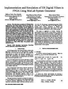
Frequency response for parallel realization. (a) g-bit passband performance. (b) g-bit stopband performance. (c) 6-bit passband performance. (d) 6-bit stopband performance.
which leads to
from which we choose G(z)=d+s+-
1
2v2 Z-A,
G(z) = k + ,-‘,“:pI
(37)
1
+
%2
l- x2z-1
(39)
where
where
k = 0.00333719 2~., = 0.07273348- jO.44989548 21~~= -0.07423120+ jO.15579206
d = 0.001836 2v, = - 0.13897453+ jO.07711481 2v, = 0.15192641- j0.33432836
with realization as in Fig. 4. For comparison purposes,we develop a parallel realizawith realization as in Fig.‘3. Alternatively, we can perform tion of H(z) using a real coefficient partial fraction expana partial-fraction expansion H(z)/i, and then multiply sion of the function through by z to obtain fw=k+
l-;lz-’
1
2
+
P*2 l- h;z-’
-0.138975352-l +O.O6296291z-2 l-1.4996z-‘+0.8482~-~ O.l5192641z-’ -O.O4722585z-2 + 1-1.5548z-‘+0.6493~-~ ’ (40)
H(z) = 0.001836+
+ 1-;2zp1 +
l-G l-
x;z-’
(38)
REGALIA
et al.:
IMPLEMENTATION
OF REAL
COEFFICIENT
DIGITAL
Frequency response plots of the different realizations are shown in Fig. 12 for 6- and S-bit coefficient quantizations. The partial fraction expansionof (37) is labeled “Complex I,” and that of (39) is labeled “Complex II.” The complex coefficient filters are seen to behave better in the passband, with comparable behavior in the stopband. For a tapped cascadedcomplex lattice realization, we begin with a complex allpass function of the form
k(z)
(z-‘-h,)(z-1-A;)
B(z) = (1- h*,z-‘)(l-
&z-l)
.
(41)
From (41) B(z) =1+p,z-‘+&z-2 with p2 = %A, = 0.69622765- j0.2567786 p1 = - (hi + A,) = - 1.5272+ j0.32277729. From (18) and (19) B’(z) =1+&z-i with pi = -0.84797446 + j0.345826. The cascadedlattice structure is shown in Fig. 9. The tap coefficients are chosen using (19) to realize a complex transfer function of the form Yo +
UlWZ>
+
Y*&)
351
FILTERS
Although the choices for G(z) above appear distinct, they in fact differ by simply an imaginary constant, consistent with the fact that given a complex rational function G(z), adding an imaginary constant leaves its conjugate symmetric part (i.e., the desired real transfer function) invariant. Fig. 13 shows the frequency responsesfor the two choices of G(z) in (43) and (45), with the label “Complex I” corresponding to (43), and “Complex II” corresponding to (45). Shown for comparison purposes is the frequency response of a real coefficient tapped Gray-Markel lattice structure realization of the same transfer function. The passbandperformance for the complex lattice structure is seento be superior, particularly for the 6-bit coefficient quantization. The real coefficient structure exhibits slightly better stopband performance, but the complex structure still gives acceptable performance in the stopband. Equivalent real hardwarerequirementsare listed in Table I, for the parallel, cascade, and lattice complex realizations, assuming a real-input/real-output even-order transfer function realization. Although the equivalent real hardware requirements are more for the complex filters described above, efficient computation schemes and processing architectures have been proposed [14]. This, combined with the reduction of filter order and favorable sensitivity properties, make the complex filters an attractive choice.
VI. CONCLUDINGREMARKS Complex coefficient digital filters, with application to The expression for G(z) as given in (40) is not unique. the processing of real sequences,have been investigated. From (34) collecting the terms corresponding to, A; and Simple methods for obtaining a complex transfer function h *, we arrive at one possible expressionfor G(z) given as from a given real transfer function have been presented, G(z) =
B(z)
G(z) =
.
(42)
0.001836+(0.00104794+ jO.41805)z-‘+(0.158748+
jO.42087)~~*
B(z) The tap coefficients for the above choice are found to be y2 = 0.4220870+ jO.15784801 y1= 0.115366155+ j0.2828518
(44
y. = 1.047796X 10e5 - jO.0538266. Similarly, from (36) collecting terms corresponding to A,, and X2, G(z) is found to be
(43)
with the observation that the complex transfer function is not unique. If the desired real transfer function has only complex poles, then a complex transfer function of half the order can always be found. This can provide improved computational efficiency, but at the expenseof requiring complex arithmetic. Various realizations of complex coefficients digital transfer functions have been outlined. Digital filters imple-
G( ) = (0.001836+ jO.6056785)+ (-0.01804313+ jO.4125192)z-’ + (0.0023119- j0.00085603)zP2 Z
B(z) with tap coefficients y2 = - 8.560277x lop4 + j2.3211904 x lop3 y1= - 0.014221906+ j0.41196111 y,, = -0.15452683- j0.26127335.
(46)
(45)
mented as a parallel realization of first-order complex sections have been shown to be minimum norm structures, and thus inherit a number of desirable properties, such as the freedom from overflow limit cycles [13], and good roundoff noise characteristics [14].
IEEE TRANSACTIONS
352
ON CIRCUITS
AND
SYSTEMS,
VOL.
Tapped
Lettice
a--bit 0.00
0.00
-
CAS-34,
NO.
4,
APRIL
1987
Coeffiolent
1,
-0.25 -8.00
-.
p -ie.oo -24.00 D -32.00
-. -.
\
-0.50
Complex I Complex II Real Ideal
\ \
.-
: , -40.00 f: & -48.00 m = -58.00
--
- - - -
\
--
\
--
py. -.
-84.00
--
,100
-8.00 -i.e.00
2
.a00
/--a, “a
0.00
c
,200
-24.0’0
Complex I Complex II Real Ideal
‘\ --32.00
,500
.400
- - - ,
“\
: ,
-40.00
f: k
-48.00
0 =
-58.00
‘“u\\ ---
-8-i.
Q