Proceedings of the 8th WSEAS International Conference on Acoustics & Music: Theory & Applications, Vancouver, Canada, June 19-21, 2007
Implementing a New Architecture of Wavelet Packet Transform on FPGA MOHSEN AMIRI FARAHANI, MOHAMMAD ESHGHI Department of Electrical and Computer engineering faculty, Shahid Beheshti University TEHRAN, IRAN
[email protected],
[email protected] Abstract: - In this paper, a new design of the Discrete Wavelet Packet Transform with efficient hardware acceleration is implemented. This design works based on the word serial pipeline architecture and the parallel filter processing. For accelerating in the Discrete Wavelet Packet Transform, a high-pass filter and a low-pass filter are used concurrently in each level. Using parallel filters makes possible that this design works two times faster than the design introduced in [10]. This architecture is implemented using internal multipliers of the FPGA and results of these implementations for the different filter lengths are presented. The AT 2 figure of merit for the implemented architecture relative to the architecture presented in [10] is smaller than 0.5. This high speed architecture is suitable for on-line applications and can be implemented for the Direct Wavelet Packet Transform with any levels of tree. Key-Words: - Tree structure, WPT, memory, processor, implementation, CLB.
1 Introduction Wavelet Transform and Wavelet Packet Transform are functions that are concentrated in time as well as in frequency around a certain point. This property, the time and frequency localization, increases the applications of these transforms [1,2]. Increasing the applications of the Wavelet Transform evolves the software implementations into the hardware implementations of it. In the recent years, the FPGA is widely used in the signal and image processing area. One of the fields that are interested is the implementation of the Discrete Wavelet Packet Transform [3]. Based on the application, there are many architectures for implementing Wavelet Packet Transform on FPGA. The speed and the occupied area are considered in these designs. An Efficient Hardware Implementation of DWT and IDWT is introduced in [4]. In this paper, by using the distributed arithmetic, the architecture works without area-consuming multipliers. In [5] Ferretti and Rizzo implemented a modified systolic architecture of the 1-D discrete wavelet transform (DWT) on the basis of the recursive pyramid algorithm (RPA). In [6] an architecture of the Wavelet Packet Transform with tree structure introduced. In this architecture the best tree for the given signal is selected, using an additive cost function. The Discrete Wavelet Packet Transform (DWPT) that works based on the filter banks is a useful tool
for the digital signal processing, the image processing [7], and data processing [8]. The applications of the WPT are increased to the biomedical fields [9]. In this paper a framework and the preliminary results of the implementation of high speed architecture of DWPT is presented that works two times faster then the implementation presented in paper [10]. The goal of this work is to investigate the feasibility of the hardware acceleration of the Discrete Wavelet Transform for data and speech compression applications. The architecture of design is introduced in paper [11] in detail. The architecture of the Wavelet Packet Transform with tree structure is introduced in section two. In section three, this architecture is implemented on FPGA and results of the implementation are presented. The comparison of the architectures and the evaluations of this architecture are presented in section four. And in the last sections, the conclusion and references are brought.
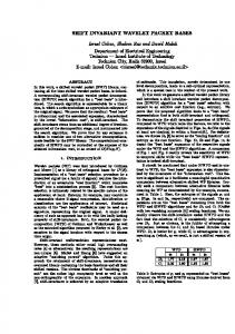
2 Architecture of Wavelet Packet Transform with tree structure In this section, a new architecture of the wavelet packet transform based on the tree structure is presented [11]. Figure 1 shows a complete 3-level Direct WPT with tree structure. In this figure the G and H blocks are the high-pass and low-pass filters, respectively. Samples are named yi,j, where i
37
Proceedings of the 8th WSEAS International Conference on Acoustics & Music: Theory & Applications, Vancouver, Canada, June 19-21, 2007
indicates the level number and j indicates the number of frequency band. In this paper number of filter coefficients, L, is considered to be equal 4 and number of decomposition level, J, is considered to be equal 3. Based on the Figure 1, at each level, after filtering, the number of samples is decimated to half [11]. The filtering and decimating process are presented in Equations (1) and (2). yi, j (n) = yi, j (n) =
L −1 ∑ k =0 L −1 ∑
g (k ). y i − 1,[ j / 2](n − 2i −1k ) (For _ high − pass _ filter) (1) h(k ). y i − 1,[ j / 2](n − 2i −1k ) (For _ low − pass _ filter ) (2)
k =0
In these equations, i, level number, is natural number and 0 ≤ i < J. j, frequency band, is natural number and 0 ≤ j < 2i, where j is an odd number in the high-pass filters, and j is an even number in the low-pass filters. And n equals 2il, where l is natural number. y0,0 ‘s are the input samples. h(k) and g(k) are the coefficients of the low-pass and the highpass non-recursive FIR filters, respectively. Based on the Figure1 and Equation (1) and (2), the coefficients at each level produce new coefficients for the next level [11]. G
G
2↓
2↓
y2,3
fy 4
G
H
y1,1
fy 2
G
H
2↓
y2,2
fy 4
2↓
y3,6 2↓ f y 8 y3,5 2↓ f y
8
H
2↓
G
2↓
H
2↓
y0,0
f
y
G
H
y2,1 2↓ f y 4
y1,0 2↓ f y 2
H
2↓
y2,0
fy 4
y3,7 fy 8
G
2↓
H
2↓
y3,4 fy 8 y3,3 fy 8 y3,2
f
y
y38,1
fy 8 y3,0 fy 8
Figure 1- A complete 3-level Direct WPT with tree structure
Figure 2 shows the main architecture for 3-level DWPT. In this figure, Mi , for i = 0,1,2 represents the memories that store the intermediate coefficients and Pi , for i = 0,1,2 represents the processors at each level.
Figure 2. Architecture for a 3-level DWPT
At each level, the number of the logical cells is equal to 2i×L. The details of these memories are as follows: • At level 0, the memory M0(k), k = 0,1,2,3, stores four input samples. • At level 1, the memory M1(k), k = 0,1,…,7, stores eight samples from the output of the processor P0 , four samples from the output of high-pass filter (y1,1’s) and four samples from the output of low-pass filter (y1,0’s) . These parts of memory M1 are named M1,1 and M1,0 respectively. • At level 2, the memory M2(k), k = 0,1,…,15, stores sixteen samples from the output of the processor P1, eight samples from the output of the high-pass filter (four samples of y2,1’s and four samples of y2,3’s) and eight samples from the output of the low-pass filter (four samples of y2,0’s and four samples of y2,2’s ). These parts of memory M2 are named M2,3-1 and M2,2-0 respectively. For examples memory M2,3-1 indicates the memory at level two that stores the output of high pass filters from level one( y2,1’s and y2,3’s). Each processor has two filters, one high-pass filter and one low-pass filter that work concurrently. Figure 3 shows the architecture of each processor. The same inputs, yi,j, are applied simultaneously to the high-pass and the low-pass filters. Since the delays of the filters are equal, the outputs of the filters are produced simultaneously. These outputs are stored in the memory of the next level. In L cycles, L inputs of the processor are multiplied to the coefficients of the high-pass and low-pass filters. At the Lth Cycle, the summation of these multiplications is stored in the next memory. The control unit controls the read and the write access in memories and generates controlling signals to manage the function of multipliers and adders in the processors [11]. To control the read and write access in
38
Proceedings of the 8th WSEAS International Conference on Acoustics & Music: Theory & Applications, Vancouver, Canada, June 19-21, 2007
memories the control unit uses an address generation circuit.
gk
High − pass filter
Multiplier
Adder & Accumulator
Multiplier
Adder & Accumulator
hk
Low − pass filter
OUT _ H
Mi OUT _ L
A 5 bits variable ‘cycle’ codes the current cycle from 0 to 31. Variables ‘ra0’, ‘ra1,0’, ‘ra1,1’, ‘ra2,20’and ‘ra2,3-1’ show the read addresses of memories and variables ‘wa0’, ‘wa1,0’, ‘wa1,1’, ‘wa2,2-0’ and ‘wa2,3-1’ show the write addresses of memories. In any CP, when flag ‘Writecycle_i’ is ‘1’, the data is written in the memory Mi. because of two inputs are written in the memories M1 and M2 concurrently, two variables are used for the writing addresses. For example, wa1,0 shows the address of logical cell in the memory M1 that the output of the low-pass filter of the level 0 processor must be stored.
Figure 3. The architecture of a processor
Based on the parallel filters operation, in the Lth clock cycles at each level, two new coefficients are produced. The schedule of the new coefficients production is shown in Table 1. Table 1. Schedule of a computation period for DWPT (J = 3). CP# is the number of input clock pulse CP #
0
Input y 0,0
y1,1(0) y1,0 (0)
1
2
p0
p1
y0,0 (1)
y 2,3 (0) y 2,2 (0) y3,7 (0) y3,6 (0)
3
4
y0,0 (2) y1,1(2) y1,0 (2)
5 6
y 2,1(0) y 2,0 (0)
y 0,0 (3)
7 8 y 0,0 (4) 9 10 y 0,0 (5)
13
14 y 0,0 (7)
y3,5 (0) y3,4 (0)
y1,1(4) y1,0 (4) y 2,3 (4) y 2,2 (4) y3,3 (0) y3,2 (0)
11 12 y 0,0 (6)
15
p2
(0)
y1,1(6) y1,0 (6)
y 2,1(4)y 2,0 (4)
y3,1(0) y3,0 (0)
.
3 Implementation of architecture The address generation circuit uses a special pattern for accessing to the memories. This pattern repeats every (0.5×2J×L×L/2) CP's. For example, for L=4 and J=3 this pattern repeats every 32 CP's. To implement the address generation circuit, the VHDL code that is shown in Figure 4 is used. Based on this VHDL code, address generation circuit uses variables as follows:
Figure 4- The VHDL codes to implement the read and write pattern of the memories
The control unit allocates twelve registers for the variables, including one 5-bit-counter for variable ‘cycle’, four 3-bit-registers for variables ‘wa2,3-1’, ‘wa2,2-0’, ‘ra2,3-1’ and ‘ra2,2-0’, six 2-bit-registers for variables ‘wa1,0’, ‘wa1,1’, ‘ra1,0’, ‘ra1,1’ ‘wa0’ and ‘ra0’ and a 1-bit-register for a flag. The presented architecture is implemented on the Xilinx X4003E FPGA using the standard VHDL. After the implementation, the results approve the
39
Proceedings of the 8th WSEAS International Conference on Acoustics & Music: Theory & Applications, Vancouver, Canada, June 19-21, 2007
schedule of the new coefficients generation in Table 1. When the internal multipliers of the FPGA are used, The results of the implementation shows that the architecture occupies %36 of CLB's on the X4003E and works with the frequency 177MHz for 3level WPT (J=3) and 4 coefficients filter(L=4).
4 Comparison of the architectures and evaluation of the architecture The implemented architecture in [10] occupies %20 of the CLB's on the X4003E and the time interval between two consequent inputs is 4 CP’s. Therefore, a read and write access pattern for the architecture in paper [10] lasts 64 CP's. Because of the number of logical cells for memories in this architecture and architecture presented in [10] is equal, the proposed architecture occupies less than doubled area relative to the architecture in [10] and occupies %36 of the CLB's on the X4003E. The time interval between two consequent inputs is 2 CP's. Therefore, a read and write address pattern for this architecture lasts 32 CP's. The AT2 figure of merit of the presented architecture relative to the architecture presented in [10] is shown in Figure 5 This figure shows the AT 2 figure of merit for J=3 stages. For example, for L=4, J=3 the AT2 figure of merit of the presented architecture with respect to the AT2 of the architecture in [10] is 0.45.
(2J-1)/J . In Table 2, the comparison between the architecture introduced in [10] and the presented architecture for 3-level WPT and the 4 coefficient filters is shown (J=3 and L=4). Table 2. Comparison of the presented architecture with the architecture presented in paper [10] for L=4, J=3.
evaluation
paper[10]
Presented paper
Time interval between 2 input
4
2
32
16
64
32
Area(%CLB)
%20
%36
AT 2
1
0.45
Frequency(MHz)
NA
177
sample (CP) Wavelet production(CP) Pattern repetition(CP)
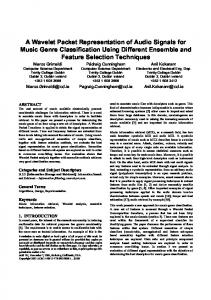
In the presented architecture, the number of multipliers is independent from the number of coefficients, but in the other architecture [12] that works based on the serial filters, the number of multipliers increases by increasing the number of coefficients. The relation between the number of coefficients and the number of multipliers in the presented architecture and the serial architectures introduced in [12] is shown in Figure 6 for J=3.
Figure 5– The AT 2 figure of merit of the presented architecture versus the number of coefficients
According to that paper [12], a serial filter uses 2L multipliers and JL memory spaces. The presented architecture uses 2J multipliers and (2J1)L memory spaces. In practice, the number of levels, J, is typically smaller than the number of coefficients, L, i.e. J«L. In this architecture, the number of multipliers is reduced by a factor of J/L, and the memory spaces are increased by a factor
Figure 6-Number of multipliers versus the number of coefficients, J=3.
40
Proceedings of the 8th WSEAS International Conference on Acoustics & Music: Theory & Applications, Vancouver, Canada, June 19-21, 2007
5 Conclusion In this paper, a new pipelined architecture for the direct wavelet packet transform that works based on the word-serial architecture [11] is implemented. By using two filters, a high-pass filter and a low-pass filter, concurrently at each level, the speed of the design is doubled. In this design, pipelined memories store the intermediate coefficients. In this architecture, the speed of producing the wavelet packet transform of the input samples, compared to this speed in the design introduced in [10], is doubled. This fast performance is obtained because in the presented architecture the latency of memories is halved. The results of implementing this architecture on FPGA shows that the sizes of memories of this design and the design presented in [10] are equal. In the presented architecture, the number of filtering elements in the processors, multipliers, adders and multiplexers, are doubled. As a result the total occupied area in the presented architecture is less than 2 times of the occupied area of [10]. The AT2 figure of merit for the implemented architecture is reduced by a factor of 0.45, relative to the architecture presented in [10], for J=3 and L=4. The results of this implementation show that by using the internal multipliers, the proposed architecture can work with 177MHz frequency. In this architecture, the space of the memory is increased by a factor of (2J-1)/J and the number of multipliers is decreased by a factor of J/L, with respect to the other serial filter architectures. This is the overhead to be paid for the speed of the presented architecture, which permits the selection of any desired WPT sub-tree. For any levels of decomposition and reconstruction, this architecture can be implemented. This highspeed architecture is more suitable for the on-line applications. References: [1] G. Strang and T. Nguyen. “Wavelets and Filter Banks”, Wellesley-Cambridge Press, 1997. [2] S.G. Mallat, “A Theory for Multiresolution Signal Decomposition: The Wavelet Representation”, IEEE Trans. on Pattern Analysis on Machine Intelligence, 110. July 1989, pp. 674693. [3] M. Nibouche, O. Nibouche, A. Bouridane, “Design and implementation of a wavelet based system”, Electronics, Circuits and Systems, 2003. ICECS 2003. Proceedings of the 2003 10th IEEE International Conference, Volume 2, 14-17 Dec.
2003 Page(s):463 - 466 Vol.2. [4] A. S. Motra, P. K. Bora, I. Chakrabarti, “An Efficient Hardware Implementation of DWT and IDWT”, Proceedings on signal processing, IEEE international conference tencon 2003. [5] M. Ferretti, D. Rizzo,“Handling Borders in Systolic Architectures for the 1-D Discrete Wavelet Transform for Perfect Reconstruction” IEEE TRANSACTIONS ON SIGNAL PROCESSING, VOL. 48, NO. 5, MAY 2000. [6] M. A. Trenas, J. Lopez, M. Sanchez, F. Arguello and E. L. Zapata, “Architecture for Wavelet Packet Transform with Best Tree”, Proceedings on Application-Specific Systems Architectures, and Processors, IEEE International Conference 2000. [7] O.Benderli, Y.C.Tekmen, N.Ismailoglu, “A Real Time, Low Latency, FPGA Implementation of the 2D Discrete Wavelet Transformation for Streaming Image Applications”, Proceeding of the Euromicro Symposium on Digital System Design (DSD’2003). [8] S. G. Mathen, “Wavelet transform based adaptive image compression on FPGA,” M.S. thesis, University of Kansas, Manhattan, Kan, USA, 2000. [9]N G Kingsbury, A Zymnis, A Pena, “DT-MRI data visualisation using the dual-tree complex wavelet transform”, Proc. IEEE Symposium on Biomedical Imaging, Arlington VA, April 15-18, 2004, paper 111. [10] Maria A. Trenas, Juan Lopez, Emilio L. Zapata. “FPGA Implementation of Wavelet Packet transform with R-econfigurable Tree Structure”, Euro micro Conference, 2000. Proceedings of the 26th Volume 1, 5-7 Sept. 2000, pp. 244 - 251 vol.1. [11] M.Amiri Farahani, M.Eshghi,“Architecture of A Wavelet Packet Transform Using Parallel Filters” accepted Proceedings on signal processing, IEEE international conference tencon 2003. [12] C. Chakrabarti, M. Vishwanath, and R. M. Owens, “Architectures for wavelets transforms: A survey”. Journal of VLSI Signal Processing, 14:171192, 1996.
41