a nonlinear active controller, with a training algorithm based on an extended ...... [8] S. Haykin, Adaptive Filter Theory, 3rd ed. Englewood Cliffs .... Technician Diploma from the University Institute of Technology in Le Creusot,. France, in 1982 ...
IEEE TRANSACTIONS ON NEURAL NETWORKS, VOL. 10, NO. 2, MARCH 1999
391
Improved Training of Neural Networks for the Nonlinear Active Control of Sound and Vibration Martin Bouchard, Member, IEEE, Bruno Paillard, and Chon Tan Le Dinh
Abstract—Active control of sound and vibration has been the subject of a lot of research in recent years, and examples of applications are now numerous. However, few practical implementations of nonlinear active controllers have been realized. Nonlinear active controllers may be required in cases where the actuators used in active control systems exhibit nonlinear characteristics, or in cases when the structure to be controlled exhibits a nonlinear behavior. A multilayer perceptron neuralnetwork based control structure was previously introduced as a nonlinear active controller, with a training algorithm based on an extended backpropagation scheme. This paper introduces new heuristical training algorithms for the same neural-network control structure. The objective is to develop new algorithms with faster convergence speed (by using nonlinear recursive-leastsquares algorithms) and/or lower computational loads (by using an alternative approach to compute the instantaneous gradient of the cost function). Experimental results of active sound control using a nonlinear actuator with linear and nonlinear controllers are presented. The results show that some of the new algorithms can greatly improve the learning rate of the neural-network control structure, and that for the considered experimental setup a neural-network controller can outperform linear controllers. Index Terms— Active control of sound and vibration, alternative backpropagation schemes, nonlinear control, nonlinear actuators, nonlinear recursive-least-squares learning algorithms.
I. INTRODUCTION
T
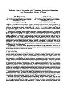
HE concept of active sound control has been known for more than 50 years. Active sound control works on the principle of destructive interference between an original “primary” disturbance sound field and a “secondary” sound field that is generated by some control actuators. For example, a classical application of active sound control is the control of sound waves in a small duct. Fig. 1 shows such a duct with an actuator and two sensors (a loudspeaker and two microphones in this case). In this example, sensor A (called a reference sensor) is used to measure an advanced information on the disturbance sound wave that propagates in the duct, and sensor B (called an error sensor) is used to monitor the performance of the active sound control system, thus providing feedback to a control algorithm. To keep this example simple, we assume that sensor A is not coupled with the actuator, so sensor A only measures the disturbance sound field. The control structure Manuscript received February 3, 1998; revised June 30, 1998 and December 1, 1998. This work was supported in part by the Institut de Recherche en Sant´e et S´ecurit´e au Travail (I.R.S.S.T.), Quebec, Canada. M. Bouchard is with the School of Information Technology and Engineering, University of Ottawa, Ottawa, Ontario K1N 6N5 Canada. B. Paillard and C. T. Le Dinh are with the Electrical Engineering and Computer Engineering Department, University of Sherbrooke, Sherbrooke, Quebec J1K 2R1 Canada. Publisher Item Identifier S 1045-9227(99)01909-8.
Fig. 1. A classical application of active sound control: The control of sound waves in ducts.
of Fig. 1 is called feedforward, because the controller feeds the actuator with a signal based on the advanced information obtained from sensor A. If the controller works properly, the signal sent in the actuator will generate a sound wave that will cancel the disturbance sound wave at the location of sensor B. Since usually only plane waves propagate in small ducts, the sound field will be uniform in any section of the duct, and the sound will be reduced from sensor B to the end of the duct. Detailed presentations of active sound control theory and applications can be found in [1]–[4]. Active sound control is certainly not limited to mono-channel feedforward one-dimensional sound field systems as in our simple example: there are also multichannel, feedback or three-dimensional active sound control systems. Also, the principle of destructive interference is not limited to the control of acoustic waves, and it has been successfully applied to the control of vibration [5]. Even though the concept is simple, it is only with the development of fast low-cost digital signal processors during the last 15 years that the implementation of practical active sound and vibration control systems has become feasible. Digital technology is well suited for adaptive control systems or control configurations where a lot of precision is required in order to achieve a good performance. A good review of the different control techniques that have been used for the active control of sound and vibration can be found in [6]. Adaptive linear filtering techniques [7], [8] have been extensively used for the active control of sound and vibration, and many of today’s implementations of active control use those techniques. A popular adaptive filtering algorithm is the multichannel filtered-X LMS algorithm (or the multierror LMS algorithm) [9], because of its simplicity and its relatively low computational load. This algorithm is a steepest descent algorithm that uses an instantaneous estimate of the gradient of the cost function (i.e., the mean squared error). Fig. 2 shows a block-diagram of the mono-channel implementation of this algorithm: the filtered-X LMS [7].
1045–9227/99$10.00 1999 IEEE
392
IEEE TRANSACTIONS ON NEURAL NETWORKS, VOL. 10, NO. 2, MARCH 1999
Fig. 2. A block-diagram of the mono-channel filtered-X LMS.
Some frequency-domain or transform-domain modifications have been proposed to improve the convergence speed of the multichannel filtered-X LMS algorithm [10], [11]. Other approaches including lattice structures, fast recursive-leastsquares algorithms or alternative structures have also been proposed to produce control algorithms with a faster convergence speed [12]–[14]. More recently, an exact low-computational version of the multichannel filtered-X LMS algorithm was published [15]. All those algorithms use adaptive FIR filters for the digital controller. However, adaptive IIR filters have also been used for the active control of sound and vibration [16], [17]. Such filters typically require less coefficients, but the convergence is not as predictable (linear) as in the case of adaptive FIR filters. The linear digital controllers described so far (using FIR filters or IIR filters) may not perform well in the cases where nonlinearities are found in an active control system. The most common source of nonlinearity in the field of active control of sound and vibration is the actuator. An actuator has typically a nonlinear response when it operates with an input signal having an amplitude close to (or above) the nominal input signal value, or when it operates in a frequency range close to (or lower than) the minimum operating frequency of the actuator (a loudspeaker for example). Nonlinear behaviors can also occur when the dynamics of the system to be controlled are nonlinear. For example, the vibration behavior of plates exhibiting buckling is nonlinear. The use of a nonlinear controller can improve the control performance on a system with a nonlinear behavior, and neural networks can be used as nonlinear controllers. For the active control of sound and vibration, the use of neural networks as nonlinear control structures has been reported [18], [19]. In [18], multilayer perceptron neural networks were used to control linear and nonlinear plants, for the active control of vibration. In [19], radial basis functions neural networks were used to build intelligent controllers that remember the optimal control parameters corresponding to different linear plant configurations, for the active control of sound. This paper will focus on the problem of nonlinear actuators (or plants) in the field of active control of sound and vibration. New heuristical algorithms will be developed for the training of the multilayer perceptron nonlinear active control structure published in [18], to increase the convergence speed and/or decrease the computational load of the algorithm described in [18]. Experiments of active sound
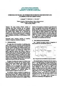
Fig. 3. Block diagram of the two neural networks control structure.
control with a nonlinear actuator will be performed, to validate the convergence properties of the developed algorithms, at least for a given experimental setup. The nonlinear control structure described in [18] used two multilayer perceptron neural networks. In that control structure, one neural network was the controller and the other network was the plant model. Fig. 3 illustrates a mono-channel implementation of a feedforward nonlinear active controller using that structure. It is clear from that figure that one neural network is the controller, and that the other neural network is the plant model. The controller network basically generates a control signal from a reference signal, and this control signal is sent to the plant through an actuator. The plant model network is required to perform the backpropagation of the error signal to the control network. Details will be given later in the paper on the use of the backpropagated signals of Fig. 3 in gradient descent or recursive-least-squares approaches, to produce learning algorithms. Two error signals are shown in Fig. 3: error signal 1 and error signal 2. Error signal 1 is the signal measured by an error sensor, and it is the error signal that is used if real-time adaptive learning of the controller neural network is required (in this case error signal 2 is not available, because the disturbance signal can not be directly measured). Error signal 2 is the error signal that is used if the training of the controller neural network is performed from recordings of the disturbance and the reference signals, or if it is performed in simulations. The training of the plant model neural network of Fig. 3 can be done with classical neural-network algorithms, including backpropagation (BP) algorithms (with or without momentum), nonlinear optimization algorithms (quasi-Newton algorithms, conjugate gradient algorithms) or nonlinear identification techniques (nonlinear Kalman filtering or nonlinear recursive-least-squares algorithms). There has been a lot of publications on such algorithms, and a review of many algorithms can be found in [20]. The training of the control neural network can not be done with those classical algorithms, because of the tapped delay lines between the two
BOUCHARD et al.: IMPROVED TRAINING OF NN’S FOR THE NONLINEAR ACTIVE CONTROL
neural networks of the control structure (Fig. 3). Using an extended backpropagation scheme, an algorithm was published in [18] for the learning of the control neural network (intuitive explanations on this algorithm will be given later in the paper). This algorithm was shown to be the generalization of the multichannel filtered-X LMS algorithm to the nonlinear case of neural networks. This algorithm will be called FX-BP in the rest of the paper. The computational load of the FX-BP backpropagations through is relatively high, because the control network have to be computed for each iteration of optimization ( is the number of delays in the tapped delay lines between the two neural networks of the control structure, Fig. 3). Also, the learning rate of the FX-BP is not particularly fast, because it is based on a backpropagation scheme (basic gradient descent scheme). To increase the convergence speed of the FX-BP algorithm, we investigated the use of nonlinear recursive-least-squares algorithms for the learning of neural networks. The EBP, MEKA, NEKA, and EKF algorithms (described in [21]) were used. It was found that those algorithms can be modified in the same way that the backpropagation algorithm was modified to produce the FX-BP algorithm (i.e., by using the same approach to compute the gradients of the cost function). However, the resulting algorithms (called FX-EBP, FX-MEKA, FX-NEKA, and FX-EKF) have a high computational load, higher than the FX-BP algorithm, and this may prevent their use in real-time applications. Consequently, details on these algorithms will not be discussed in this paper, and readers interested in these algorithms should refer to [22]. To reduce the computational load of the algorithms used for the training of the control network of Fig. 3, an alternative approach was used. It is easy to see that the two neuralnetworks’ control structure is actually a particular case of a FIR multilayer neural network (a multilayer perceptron network where all weights are FIR filters [20]). The approach developed for the computation of the gradients of the cost function in those networks [23] can thus be used to compute the gradients of the cost function for the controller neural network. By combining this gradient computation technique with a steepest descent approach, an algorithm that we called adjoint-BP can be developed. This algorithm has a lower computational load than the FX-BP. The further simplification of this algorithm to the linear case (one layer of neurons in each network, with linear activation functions) produces the multichannel adjoint-LMS algorithm [24], that was recently published as a low-computational alternative to the multichannel filtered-X LMS algorithm. The term adjoint will be used in this paper for the algorithms that use the same approach as the adjoint-LMS or the adjoint-BP for the computation of the gradient of the cost function (as opposed to the filtered-X approach). Recalling that increased convergence speed for the learning of the control network is an objective of this work (with reduced computational load being the other objective), nonlinear recursive-least-squares methods will be combined with the adjoint approach of computing the gradient of the cost function. The resulting algorithms will be called adjoint-EBP, adjoint-MEKA, adjoint-NEKA, and adjoint-EKF.
393
There is an intuitive way of distinguishing the filtered-X approach and the adjoint approach for the computation of the instantaneous gradient of the mean quadratic error (or the gradient of the instantaneous quadratic error). The filtered-X approach is based on the fact that the instantaneous quadratic error at time n is influenced by the values that the weights of the control network had in the last samples (weight As mentioned before, values at time is the number of delays in the tapped delay lines before the plant model network (Fig. 3). At the opposite, the adjoint approach is based on the fact that the weights of the control neural network at time will affect the cost function (quadratic next samples. This can be reformulated in error) for the a causal way: the weights of the control neural network at time influenced the cost function of the last samples (quadratic error signals at time The mathematical formulation of these statements for a monochannel system is as follows. Filtered-X approach: instantaneous gradient
(1)
Adjoint approach: instantaneous gradient
(2)
where Square of the error signal at time (instantaneous cost function). Value of a weight in the control neural network . at time As it will explicitly appear later in the paper, the adjoint backpropaapproach does not require the computation of gations through the control network, and thus its computational load is lower than for the filtered-X approach. The drawback of the adjoint approach is that if causality is a constraint (as in control applications), then the modifications to the control weights at time have to be performed with the reference sam(i.e., ples and the backpropagated error samples of time there is a delay of samples in the adaptation process). This could slow down the tracking rate of a control network in the case of fast time-varying reference and disturbance signals. In Section II, the FX-BP algorithm published in [18] is described and five new adjoint algorithms are introduced for the training of the multilayer perceptron controller network: one using a gradient descent algorithm and four using nonlinear recursiveleast-squares algorithms. In Section III, experimental results of feedforward active sound control in a duct using a nonlinear actuator with linear and nonlinear controllers are presented. The performance of the different nonlinear training algorithms is compared, showing that some new heuristical algorithms introduced in this paper can greatly improve the learning rate of the controller neural network (compared to the FX-BP). Control results also show that a multilayer perceptron neuralnetwork control structure can outperform linear controllers for the considered experimental system.
394
IEEE TRANSACTIONS ON NEURAL NETWORKS, VOL. 10, NO. 2, MARCH 1999
II. DESCRIPTION OF THE LEARNING ALGORITHMS FOR THE CONTROLLER NEURAL NETWORK To keep the equations as readable as possible, all the algorithms described in the rest of the paper will be written for the mono-channel control case. The extension of the algorithms to the multichannel case is quite straightforward, and interested readers should refer to [18] and [22] for the multichannel forms of the algorithms. The equations for the forward propagation in the multilayer perceptron neuralnetwork control structure are common to all the algorithms that will be described in this paper, and they will be presented first. They are given by (3)–(11). • For the input layer of the control network (3) • For the other layers of the control network (4) (5) • For the input layer of the plant model network
model has been identified previously to the training of the control network); error signal at time ; disturbance signal at time ; activation function of a neuron; layer index; neuron index of an upper layer (relative to ); neuron index of a lower layer (relative to ). index of an output layer. As mentioned earlier, the computation of the error signal in (9) is only performed if the training of the controller neural network is done with recordings of the reference and disturbance signals, or in simulations. If the training is performed in real-time in a practical control system, then the is the signal measured by the error sensor. When signal neural networks are used as a nonlinear regression tool (as is usually a it is the case here), the activation function nonlinear function for all neurons excepted the neurons of an is usually linear]. The following output layer [for which equations describe the activation functions used in this paper: for neurons of an output layer
(10)
(6) • For the other layers of the plant model network
for all other neurons (7) (8)
• For the output layer of the plant model (9) where signal from the reference sensor at time ; value of neuron in the input layer of the control network at time ; output of neuron in layer of the control ; network at time signal at the output of the control network at ; time weighted sum of inputs for neuron of layer m of the control network at time ; value at time of the weight linking neuron of layer to neuron of layer of the control network; value of neuron in the input layer of the plant model network at time ; output of neuron in layer m of the plant model network at time ; signal at the output of the plant model network at time ; weighted sum of inputs for neuron of layer of the plant model network at time ; value of the weight linking neuron of layer to neuron of layer of the plant model network (note that these weights are constant, because it is assumed that the plant
was used
(11)
It should be noted that the bias (DC offsets) weights are implicitly included in (4) and (7). The FX-BP published in [18] can now be introduced. This algorithm uses the standard backpropagation scheme to backpropagate the gradients of the instantaneous quadratic error through the plant model network, and it uses the approach of (1) to compute and backpropagate the gradients in the control network. The weights in the control network are then modified according to a steepest descent method. The result is summarized by (12)–(16). FX-BP algorithm: • For the last layer of the plant model network (12) • For the other layers of the plant model network (except the input layer) (13) • For the last layer of the control network (14) • For the other layers of the control network (except the input layer)
(15) • For all the weights in the control network (16)
BOUCHARD et al.: IMPROVED TRAINING OF NN’S FOR THE NONLINEAR ACTIVE CONTROL
395
• For all the weights in the control network
where gradient of the instantaneous quadratic error ; relative to gradient of the instantaneous quadratic error ; relative to gradient of the instantaneous quadratic error ; relative to gradient of the instantaneous quadratic error ; relative to adaptation gain scalar; neuron index of an upper layer (relative to ); neuron index of a lower layer (relative to ); number of delays in the tapped delay line between the control network and the plant model network (Fig. 3). Equation (16) shows that the backpropagation through the control network [(14) and (15)] and the update of the weights times. This can in the control network are computed cause the computational load of the FX-BP algorithm to be in (15) (i.e., very high. By assuming assuming that the adaptation is slow enough so that does not significantly change in iterations of optimization), the amount of memory that is required by the algorithm can be greatly reduced. The adjoint-BP algorithm can now be introduced, because it has of lot of similarities with the FX-BP algorithm. Like the FX-BP algorithm, the adjoint-BP algorithm uses the standard backpropagation scheme to backpropagate the gradients of the instantaneous quadratic error through the plant model network, but it uses the approach of (2) to compute and backpropagate the gradients in the control network [instead of the approach of (1)]. Like in the FX-BP algorithm, the weights in the control network are modified according to a steepest descent method. The adjoint-BP algorithm is described by (17)–(21). Adjoint-BP algorithm: • For the last layer of the plant model network (17) • For the other layers of the plant model network (except the input layer) (18) • For the last layer of the control network
(21) where sum of the gradients of the past instantaneous quadratic errors relative to ; sum of the gradients of the past instantaneous quadratic errors relative to In the adjoint-BP algorithm, no equation has to be computed times (like in the FX-BP algorithm), but there is a double summation in (19). Nevertheless, the computational load of the adjoint-BP will usually be lower than the computational load of the FX-BP algorithm, in particular when there are a lot of weights in the control neural network (because in this backpropagations through the control network case the performed by the FX-BP require a lot of computations). Like in the FX-BP algorithm, by assuming in (20) (i.e., assuming small changes to the weights during iterations), the amount of memory required can be greatly reduced. This is also true for the four other adjoint algorithms that will be introduced in this paper. The steepest descent approach is simple and has a low computational load compared to more sophisticated optimization methods, but it is usually not a fast convergence method. To increase the convergence speed of the adjoint-BP algorithm, nonlinear identification (or nonlinear recursive-least-squares) approaches based on [21] will be used instead of the steepest descent approach. The first two recursive-least-squares algorithms, the adjoint-EBP and adjoint MEKA algorithms, will locally (for each neuron) minimize the quadratic value of or a similar quantity. The only difference between the two algorithms is that the adjoint-EBP minimizes the and the adjointquadratic gradients relative to MEKA minimizes the quadratic gradients relative to This is an indirect approach to locally minimize the quadratic error function (i.e., if the quadratic gradients are minimized, then the quadratic error of the control system will be at a local minimum). As opposed to the steepest descent approaches, the convergence speed of the recursiveleast-squares approaches does not depend on the eigenvalue spread of the autocorrelation matrix of the input signals in each neuron, and increased convergence speed can be expected. The adjoint-EBP algorithm is described by (22)–(29). Adjoint-EBP algorithm: • for the last layer of the plant model network (22) • for the other layers of the plant model network (except the input layer)
(19) • For the other layers of the control network (except the input layer)
(23) • for the last layer of the control network
(20) (24)
396
IEEE TRANSACTIONS ON NEURAL NETWORKS, VOL. 10, NO. 2, MARCH 1999
• for the other layers of the control network (except the input layer)
(25)
neuron in the control network, as compared to gain vectors and inverse correlation matrices for each layer in the adjoint-EBP algorithm. The adjoint-MEKA thus has a higher computational load and requires more memory. Adjoint-MEKA algorithm: • For the last layer of the plant model network
• for all the layers in the control network (except the input layer)
(31) • For the other layers of the plant model network (except the input layer) (32)
(27)
• For the last layer of the control network (33)
(28)
• For the other layers of the control network (except the input layer)
• for all the weights in the control network (34) (29) • For all the layers in the control network (except the input layer)
where and
parameters of the Riccati equations inherent to recursiveleast-squares methods: gain vector, inverse correlation matrix, and forgetting factor; vector composed of all the components of ; layer vector composed of all the weights connected to neuron of layer ; adaptation gain scalar. As previously mentioned, the adjoint-MEKA is similar to the adjoint-EBP, but it minimizes quadratic gradients relative instead of It was reported in [21] to that a MEKA-based algorithm sometimes has better convergence properties than a EBP-based algorithm. To describe the adjoint-MEKA algorithm, it is first required to linearize the activation function of each neuron [(30)]
(35) (37)
(38)
(39) • For all the weights in the control network (40) where and
(30) The adjoint-MEKA algorithm can then be described by (31)–(39). Note that in the adjoint-MEKA algorithm there are gain vectors and inverse correlation matrices for each
parameters of the Riccati equations inherent to recursive-leastsquares methods: gain vector, inverse correlation matrix, and forgetting factor; product of and ; sum of the gradients of the past instantaneous quadratic er; rors relative to sum of the gradients of the past instantaneous quadratic er. rors relative to
BOUCHARD et al.: IMPROVED TRAINING OF NN’S FOR THE NONLINEAR ACTIVE CONTROL
There is an alternative to minimizing local quadratic values or (the local gradients of the of quadratic error), as done in the adjoint-EBP and adjointMEKA algorithms. The alternative is for all the neurons to minimize a common value of the quadratic gradient of the squared error. This gradient is computed at the output of the control network [the gradient is then the previously defined ]. By linearizing the activation function at the output of the control network as a function of the weights in the controller network, recursive-least-squares equations can be used and new training algorithms can be developed. The linearization of the activation function at the output of the control network is described by (41)
397
• For the other layers of the control network (except the input layer) (46) • For all the layers in the control network (except the input layer) (47)
(48)
(49) (50) (41) where vector containing all the weights of the control network; output of the control network expressed as a function of
where gradient of relative to gradient of relative to product of and Adjoint-EKF algorithm: • For the last layer of the plant model network
.
; ; .
(51)
and the gradient at the Combining (41) with the recursiveoutput of the control network least-squares equations, the adjoint-NEKA algorithm and the adjoint-EKF algorithm can be introduced. The adjoint-NEKA and algorithm is a simplified algorithm where the vectors contain only information (weights, gradients) related to a specific neuron, while the adjoint-EKF algorithm and vectors containing information uses on all neurons of the control network. Equations (42)–(50) describe the adjoint-NEKA algorithm, and (51)–(59) describe the adjoint-EKF algorithm. Adjoint-NEKA algorithm: • For the last layer of the plant model network
• For the other layers of the plant model network (except the input layer) (52) • For the last layer of the control network (53) (54) • For the other layers of the control network (except the input layer)
(42) • For the other layers of the plant model network (except the input layer)
(55) • For the whole control network
(43) .. .
(56)
• For the last layer of the control network (44) (45)
(57)
398
IEEE TRANSACTIONS ON NEURAL NETWORKS, VOL. 10, NO. 2, MARCH 1999
Fig. 4. Experimental setup.
(58) (59) where vector built with the product of all the and values in the control network; and
parameters of the Riccati equations inherent to recursive-least-squares methods: gain vector, inverse correlation matrix, and forgetting factor; vector containing all the weights in the control network. The computational load of the adjoint-EKF algorithm is higher than for the other adjoint algorithms (like the EKF algorithm required more computations than the EBP, MEKA, and NEKA algorithms [21]), because the computation of (57) and (58) requires a lot of adds/multiplies. But it can be expected that the adjoint-EKF will exhibit a faster convergence behavior because it takes into account the correlation between vector. all the values in the global III. EXPERIMENTAL RESULTS Some real-time control experiments of active control of sound in a duct using a nonlinear actuator were performed, in order to evaluate the performance of linear and nonlinear controllers using different learning algorithms. The disturbance signal was chosen to be a 50 Hz pure tone signal of large amplitude, because it was expected that this would cause the control actuator to exhibit nonlinear characteristics. Fig. 4 shows the experimental setup, including a duct, two actuators (loudspeakers), a sensor (a microphone), anti-aliasing and reconstruction filters, a power amplifier, a preamplifier, A/D
and D/A converters, a PC and a DSP processor. An impact microphone (Larson–Davis model 2530) that can measure acoustic levels up to 180 dB was used as the error sensor, to make sure that the nonlinearity was produced by the control actuator and not by the microphone. The microphone was located 8 in from the end of the duct, and the control loudspeaker was located 20 in from the same end of the duct. The control loudspeaker was a small 4 in loudspeaker (Radio Shack model 40-1022B), that would obviously be nonlinear for strong levels of 50 Hz excitation signals. To produce a large amplitude pure tone disturbance sound field (primary field) at 50 Hz, a powerful 12 in loudspeaker (JBL model E120-8) was used. This disturbance loudspeaker was located 4 ft from the end of the duct. The DSP used for the realtime computations (forward propagation) was a TMS320C31 floating point processor, and a PC (Pentium 200 MHz) was used for the off-line training of the neural networks. The DSP board was used both as the disturbance generator (feeding the disturbance actuator) and as the controller (feeding the control actuator). This simplistic approach (no reference sensor required) was used to focus on the problem of the nonlinearity of the control actuator. In the case of nonlinear controllers, the different learning algorithms described in the previous section were tested, while the classical FX-LMS algorithm (Fig. 2) was used as the learning algorithm for the linear controller (FIR filter). Fixed (nonadaptive) controllers were used. The solution of those controllers was computed from recordings of the reference and disturbance signals (disturbance generator and error sensor signals). When the learning algorithm had converged to a good control solution or when a certain number of iterations of optimization had been performed, the solution of the controller was copied into the TMS320C31 DSP, where the forward propagation [(3)–(5)] was computed in real-time for the control network of Fig. 3. In the experiments, a double-precision floating point representation was used for the learning algorithms (on a PC), and a single precision floating point representation was used for the forward propagation on the DSP. The sampling frequency used for the experiments was 450 Hz, with low-pass filters (eighth order Butterworth low-pass filters) having a cutoff frequency of 150 Hz. For the nonlinear control, the number of neurons in the fully connected networks were 12-6-1 for the plant model network and 2-6-1 for the control network. For the linear control, FIR filters with 12 coefficients for the plant model and eight coefficients for the controller were used. An identification of the plant model was always performed before the control stage, using the EKF algorithm [21] for the nonlinear identification, or the LMS algorithm for the linear identification. The nonlinear identification process initially caused some problems. Because the actuator signal at the control stage will always be different from the actuator excitation signal during the identification stage, nothing guarantees that a nonlinear harmonic model identified with a good precision during the identification stage will perform well during the control stage (unless the same combination of frequencies, amplitudes and phases are sent as inputs to the model during both identification and control stages). An approach was however successful
BOUCHARD et al.: IMPROVED TRAINING OF NN’S FOR THE NONLINEAR ACTIVE CONTROL
399
Fig. 5. Power spectrum of the disturbance signal (error sensor without control).
Fig. 7. Power spectrum of the error signal with an adaptive linear controller trained with the FX-LMS algorithm.
Fig. 6. Power spectrum of the error signal with a fixed linear controller trained with the FX-LMS algorithm.
Fig. 8. Power spectrum of the error signal with a fixed nonlinear controller trained with the adjoint-NEKA algorithm.
in achieving a good nonlinear control performance with a given plant model: the use of several recordings of excitation signals having different frequencies and different amplitudes to perform the learning of the plant model network. The frequencies that were used as excitation signals during the identification stage were the frequency of the disturbance (50 Hz) and its first harmonics (100 and 150 Hz). Fig. 5 shows the power spectrum of the 50 Hz disturbance signal (primary field, error sensor signal without control). The power spectrum of the error signal obtained with a linear FIR controller trained with a FX-LMS algorithm is shown in Fig. 6. It can be observed that the controller does significantly reduce the 50 Hz tone (over 20 dB of reduction), but the nonlinearity of the loudspeaker generates harmonics of the 50 Hz tone: tones at 100 and 150 Hz. The linear controller thus only produces a global 6.5 dB reduction of the disturbance. Moreover, the sound emitted from the duct without control is perceptually less disturbing than the sound emitted with the control on, because the ear is more receptive to the 100 and 150 Hz frequencies. The limitation of 20 dB of reduction was due to the use of a fixed controller, where the imprecision of the linear model of the nonlinear plant could not be compensated at the control stage. To illustrate this, Fig. 7 shows the error signal that was produced with a real-time adaptive linear controller using the same plant model and the same FX-LMS algorithm. It is clear that in this case the 50 Hz tone is greatly reduced (60 dB of reduction), but the global reduction of the disturbance is still 6.5 dB, because of the harmonics generated by the nonlinear actuator.
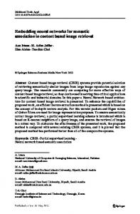
The nonlinear controllers produced by the FX-BP, the adjoint-BP, the adjoint-EBP and the adjoint-MEKA algorithms all gave practical control results that were better than the linear FIR control results (between 1 and 3 dB of increase of the global sound reduction), but it was the controllers produced by the adjoint-NEKA and adjoint-EKF algorithms that gave the best control results: an increase of more than 13 dB of the global sound reduction compared to linear control results. Fig. 8 shows the power spectrum of the error signal obtained with a nonlinear controller trained with the adjoint-NEKA algorithm. This controller reduces the 50 Hz tone by 30 dB, but most of all the level of the harmonics that the actuator generates in this case is 15 dB lower than with the linear controller. The global reduction in this case is 21 dB, thus greatly improving the 6.5 dB reduction obtained from either the fixed or the adaptive linear controller. It should be noted that the nonlinear characteristics of the actuator have not been completely eliminated by the nonlinear controller, as can be seen by comparing the amplitude of the 100 Hz and 150 Hz components in Figs. 5 and 8. It is possible that real-time adaptive nonlinear controllers could improve the performance by compensating at the control stage for some imprecision in the plant model, as did the adaptive linear controller discussed in the previous paragraph. The better practical control results for the adjoint-NEKA and the adjoint-EKF algorithms could be expected from the learning curves of the different algorithms. Fig. 9 shows the learning curves for the six nonlinear training algorithms that were tested at the control stage: FX-BP, adjoint-BP, adjoint-
400
IEEE TRANSACTIONS ON NEURAL NETWORKS, VOL. 10, NO. 2, MARCH 1999
(a)
(b) Fig. 9. Learning curves of the different nonlinear training algorithms (a) FX-BP, adjoint-BP, adjoint-EBP, adjoint-MEKA (b) FX-BP, adjoint-NEKA, adjoint-EKF.
j
4
2
j
EBP, adjoint-MEKA, adjoint-NEKA and adjoint-EKF. It is clear from that figure that the adjoint-NEKA and adjointEKF algorithms produced a much faster convergence speed than all the other nonlinear learning algorithms. It should also be noted that the adjoint-BP produces a performance almost as good as the previously published FX-BP algorithm, while requiring less computations than the FX-BP. Due to the limited accuracy of the nonlinear plant models, the practical control performance was not always as good as the performance predicted during the training of the controllers. For example, the adjoint-EKF algorithm produced a 40 dB reduction during the (simulated) learning stage, and produced only 20 dB of practical sound reduction during the control stage (similar to the adjoint-NEKA algorithm). The consistency and predictability of the performance produced by the neural-network training algorithms was not as good as for the linear controllers training algorithms, that were based on linear adaptive filtering. This was expected, and it was also reported in [18]. In particular, the values for the adaptation gains were adjusted by trial and error, to produce a fast convergence. More theoretical work on the convergence and stability of the heuristical training algorithms introduced in this paper or in [18] would thus be useful. However, it was found that the random initial values of the weights in the controller network had little effect on the performance produced by the different learning algorithms. IV. CONCLUSION In this paper, new heuristical algorithms were introduced for the learning of a multilayer perceptron neural-network
control structure suitable for the active control of sound and vibration. With comparison to the previously published FX-BP algorithm [18], the objective was to develop algorithms with a faster convergence speed (this was achieved by the use of nonlinear recursive-least-squares techniques) and/or a lower computational load (this was achieved by using the adjoint approach for the computation of the gradients). Experiments of feedforward active sound control in a duct using a nonlinear actuator with linear and nonlinear controllers were performed. It was observed that for this system, some new algorithms introduced in this paper could greatly improve the learning rate of the controller neural network (compared to the FXBP), or produce similar learning rates while requiring less computations. Control results also showed that a multilayer perceptron neural-network control structure could outperform linear controllers for the experimental nonlinear system. Future work related to this paper could include more theoretical research on the convergence and stability of the training algorithms, to improve their predictability and consistency. Other future work could be the investigation of methods for improving the identification of valid nonlinear models of the plant, and the development of numerically robust implementations of the introduced recursive-least-squares algorithms (for real-time implementations). REFERENCES [1] S. J. Elliott and P. A. Nelson, “Active noise control,” IEEE Signal Processing Mag., vol. 10, pp. 12–35, 1993. [2] P. A. Nelson and S. J. Elliott, Active Control of Sound. London, U.K.: Academic, 1992. [3] M. O. Tokhi and R. R. Leitch, Active Noise Control. Oxford, U.K.: Clarendon, 1992. [4] E. F. Berkman and E. K. Bender, “Perspectives on active noise and vibration control,” Sound and Vibration, vol. 31, pp. 80–94, 1997. [5] C. R. Fuller, S. J. Elliott, and P. A. Nelson, Active Control of Vibration. London, U.K.: Academic, 1996. [6] S. M. Kuo and D. R. Morgan, Active Noise Control Systems: Algorithms and DSP Implementations. New York: Wiley, 1996. [7] B. Widrow and S. D. Stearns, Adaptive Signal Processing. Englewood Cliffs, NJ: Prentice-Hall, 1985. [8] S. Haykin, Adaptive Filter Theory, 3rd ed. Englewood Cliffs, NJ: Prentice-Hall, 1996. [9] S. J. Elliott, I. M. Stothers, and P. A. Nelson, “A multiple error LMS algorithm and its application to the active control of sound and vibration,” IEEE Trans. Acoust., Speech, Signal Processing, vol. 35, pp. 1423–1434, 1987. [10] Q. Shen and A. Spanias, “Frequency-domain adaptive algorithms for multichannel active sound control,” in Proc. 2nd Conf. Recent Advances in Active Control of Sound and Vibrations, Blacksburg, VA, 1993, pp. 755–766. [11] M. Bouchard and B. Paillard, “A transform domain optimization to increase the convergence speed of the multichannel filtered-X LMS algorithm,” J. Acoust. Soc. Amer., vol. 100, pp. 3203–3214, 1996. [12] T. Auspitzer, D. Guicking, and S. J. Elliott, “Using a fast-recursiveleast-squared algorithm in a feedback-controller,” in Proc. IEEE ASSP Workshop Applicat. Signal Processing Audio Acoust.s, Mohonk Mountain House, NY, 1995. [13] Y. C. Park and S. D. Sommerfeldt, “A fast adaptive noise control algorithm based on the lattice structure,” Appl. Acoust., vol. 47, pp. 1–25, 1996. [14] I. S. Kim, H. S. Na, K. J. Kim, and Y. Park, “Constraint filtered-x and filtered-u least-mean-square algorithms for the active control of noise in ducts,” J. Acoust. Soc. Amer., vol. 95, pp. 3379–3389, 1994. [15] S. Douglas, “Fast, exact filtered-x LMS and LMS algorithms for multichannel active noise control,” in Proc. ICASSP-97, Munich, Germany, 1997, pp. 399–402. [16] L. J. Eriksson, “Development of the filtered-u algorithm for active noise control,” J. Acoust. Soc. Amer., vol. 89, pp. 257–265, 1991.
BOUCHARD et al.: IMPROVED TRAINING OF NN’S FOR THE NONLINEAR ACTIVE CONTROL
[17] L. J. Eriksson, M. C. Allie, and R. A. Greiner, “The selection and application of an IIR adaptive filter for use in active sound attenuation,” IEEE Trans. Acoust., Speech, Signal Processing, vol. 35, pp. 433–437, 1987. [18] S. D. Snyder and N. Tanaka, “Active control of vibration using a neural network,” IEEE Trans. Neural Networks, vol. 6, pp. 819–828, 1995. [19] M. O. Tokhi and R. Wood, “Active noise control using radial basis function networks,” Contr. Eng. Practice, vol. 5, pp. 1311–1322, 1997. [20] S. Haykin, Neural Networks: A Comprehensive Foundation. Englewood Cliffs, NJ: Macmillan, 1994. [21] S. Shah, F. Palmieri, and M. Datum, “ Optimal filtering algorithms for fast learning in feedforward neural networks,” Neural Networks, vol. 5, pp. 779–787, 1992. [22] M. Bouchard, D´eveloppement et Validation d’Algorithmes a` Convergence Rapide Pour l’Apprentissage de R´eseaux de Neurones Utilis´es en Contrˆole Actif Nonlin´eaire, Ph.D. dissertation, Universit´e de Sherbrooke, Canada, 1997. [23] E. A. Wan, “Temporal backpropagation for FIR neural networks,” in Proc. IEEE Int. Joint Conf. Neural Networks, San Diego, CA, vol. 1, pp. 575–580, 1990. , “Adjoint-LMS: An efficient alternative to the filtered-X LMS [24] and multiple error LMS algorithms,” in Proc. ICASSP 96, vol. 3, pp. 1842–1845, 1996.
Martin Bouchard (M’98) received the B.Ing., M.Sc.A., and Ph.D. degrees in electrical engineering from the University of Sherbrooke in 1993, 1995, and 1997, respectively. He worked in an instrumentation group at Bechtel in 1991 and in a real-time software group at CAE Electronics, Inc., from 1992 to 1993. From 1993 to 1997, he was a signal processing Research Assistant at the Group of Acoustics and Vibration of the University of Sherbrooke. From 1995 to 1997, he also worked in SoftDb Active Noise Control Systems Inc. which he cofounded. In January 1998, he joined the University of Ottawa, where he is currently an Assistant Professor at the School of Information Technology and Engineering (SITE). His current research interests are adaptive filtering, neural networks, active control of sound and vibrations, and 3-D audio/binaural hearing/transaural hearing. Dr. Bouchard is a member of the Ordre des Ing´enieurs du Qu´ebec, the Audio Engineering Society, and the Acoustical Society of America.
401
Bruno Paillard was born in Cannes, France, in 1962. He received the Technician Diploma from the University Institute of Technology in Le Creusot, France, in 1982, and the bachelor’s degree in electrical engineering from the INSA, Lyon, France, in 1985. In 1987 and 1992, he received the Master’s and Ph.D. degrees on auditory modeling and perceptual coding of audio signals, from the University of Sherbrooke, Canada. He is now Professor of Electrical and Computer Engineering at the University of Sherbrooke. His current research interests include active control of noise and vibration and motion control, focusing on algorithms, adaptive signal processing, and real-time DSP implementations.
Chon Tam Le Dinh was born in Vietnam. He received the Ph.D. degree in electrical engineering from the University of Sherbrooke, Quebec, Canada, in 1977. He worked for CRIQ, the Industrial Research Center of Qu´ebec, for 18 years in Montr´eal. Since 1991, he has been Associate Professor in the Department of Electrical and Computer Engineering, at the University of Sherbrooke. His current interests include signal processing, video processing, and neural networks.