{yrj,ligy}@ios.ac.cn. Abstract. Based on the equivalence relation for location based reach- ability between continuous and integer semantics of closed timed au-.
Improvements for the Symbolic Verification of Timed Automata� Rongjie Yan1,2 , Guangyuan Li1 , Wenliang Zhang1,2 , and Yunquan Peng1,2 1
2
State Key Laboratory of Computer Science Institute of Software, Chinese Academy of Sciences,Beijing,100080,China Graduate School of the Chinese Academy of Sciences,Beijing,100039,China {yrj,ligy}@ios.ac.cn
Abstract. Based on the equivalence relation for location based reachability between continuous and integer semantics of closed timed automata, Beyer et al. have implemented the verifier Rabbit, with the uniform representation of reachable configurations. However, the growth of maximal constant of clock variables will decline the performance of Rabbit. The paper proposes an improved symbolic method, using binary decision diagrams (BDDs) to store the symbolic representation of discretized states, for the verification of timed systems. Compared with Rabbit, experiments demonstrate that besides the memory reduction, our implementation is also less sensitive to the size of clock domain. Keywords: verification, timed systems, symbolic method, BDD.
1
Introduction
Formal verification is one of the effective methods to ensure the correctness of real-time systems. Timed automata (TAs) [1] provide a formal framework for the automatic analysis and verification of real-time systems, and in the past few years several tools for the model checking of TAs have been developed and used, including Uppaal [13], Kronos [8], Red [16], Rabbit [6] and FPTA [17], which have implemented the computation for the set of all reachable configurations by reachability analysis. However, the exploding increase of time consumption for the computation and memory consumption for the representation of the reachable configurations is still a main problem. Within the model checking community, many works were based on symbolic representations of the state space. The region equivalence of [1] is the precursor of the symbolic methods in which the state space is covered using regions with the same integer parts of clock values and the ordering of fractional parts. Currently, most of real-time verifiers apply abstractions based on zones (the constraint sets) in order to be coarser. Difference bound matrices (DBMs) [4] are a common data structure to describe zones. However, this structure cannot �
Supported by 973 Program of China under Grant No. 2002cb312200; and the National Natural Science Foundation of China under Grant Nos. 60673051, 60421001.
J. Derrick and J. Vain (Eds.): FORTE 2007, LNCS 4574, pp. 196–210, 2007. c IFIP International Federation for Information Processing 2007 �
Improvements for the Symbolic Verification of Timed Automata
197
unify the representation of configurations which consist of locations and clock valuations. Besides DBMs, clock difference diagrams (CDDs) [3] and their variants [16,15] were used to combine the representation of locations and clock valuations in zones. Their common disadvantage is that the lack of a unique canonical representation may hinder the containment relation detection. The work in [9] introduced the BDD representation of reachable configurations based on the methods of time discretization [10]. The work in [2] proposed that closed timed automata (CTAs), whose clock constraints only contain ≥, ≤ relations, can just consider integer clock valuations for the reachability analysis. Based on the observation in [2], the work in [5] implemented BDD-based reachability analysis, which formally defined the integer semantics of closed automata and proved the equivalence between integer and continuous semantics for location based reachability. All these BDD-based verifiers share the same problem of BDD’s: they are sensitive to the size of clock domain. Based on the work of [5], we introduce symbolic structures for the representation of reachable configurations, in the integer semantics of closed timed automata, which is similar to the work of [17]. To reduce the memory consumption, BDD is applied to store the reachable symbolic sets. The combination not only reduces the sensitivity to the scale of clock constants, but also unifies the representation of locations and clock valuations. The paper is organized as follows. In section 2, we briefly recall the definition of TAs, CTAs and their semantics. In section 3, we present the new symbolic data structures and the reachability analysis algorithm for the integer semantics. In section 4, we demonstrate the performance of our prototype implementation. Section 5 concludes and discusses future work.
2
Preliminaries
The section introduces the definition of TAs and their continuous and integer semantics. A timed automaton (TA), proposed by Alur and Dill [1], is a finite state automaton extended with a finite set of real-valued clock variables. Definition 1. (Syntax of Timed Automata). Let X be a finite set of clocks, and C(X) be the clock constraint set over X, given by the syntax: φ ::= (x ∼ c) | φ1 ∧ φ2 | true where x ∈ X, ∼∈ {, ≥} and c ∈ N+ (N+ is the set of non-negative integers). A timed automaton over X is a tuple A = �L, l0 , Σ, X, I, E�, where – L is a finite set of locations, and l0 ∈ L is the initial location, – I is a mapping that labels each location l ∈ L with some constraint in C(X),and I(l) is called the invariant of l,
198
R. Yan et al.
– Σ is a finite set of synchronization labels, and – E ⊆ L × C(X) × Σ × 2X × L is the set of transitions. A transition (l, g, σ, Y, l� ) ∈ E means that one can move from the location l to l� through a transition labelled with σ ∈ Σ. Moreover, g the guard must be satisfied by the current clock values, and all the clocks in Y (Y ⊆ X) are reset to 0. Closed timed automata [2] restrict the clock constraints. The restricted constraints φ over X is: φ ::= x ≤ c|x ≥ c|φ1 ∧ φ2 , where x ∈ X, and c ∈ N+ . 2.1
Continuous Semantics of TA
In continuous semantics, clock variables have non-negative real valuations. A clock valuation is a function μ : X → R+ , where R+ is the set of non-negative reals. μX denotes the set of all clock valuations over X. For t ∈ R+ , μ+ t denotes the clock valuation such that μ(x + t) = μ(x) + t, for all x ∈ X. For Y ⊆ X, μ[Y := 0] denotes the clock valuation such that μ[Y := 0](x) = 0, for all x ∈ Y and otherwise μ[Y := 0](x) = μ(x). μ satisfies a constraint φ ∈ C(X), denoted by μ |= φ, if φ evaluates to true under the assignment given by μ. The continuous semantics of a timed automaton A = �L, l0 , Σ, X, I, E� over X is defined as a transition system �S, s0 , Σ ∪ R+ , →�, where S = L × μX ; s0 = (l0 , μ0 ) is the initial state where μ0 (x) = 0 for all x ∈ X; and the transition relation → comprises two kinds of moves: δ
→ (l, μ + δ), if δ ∈ R+ and μ |= I(l) and μ + δ |= I(l); – delay transition: (l, μ) − σ – discrete transition: (l, μ) − → (l� , μ[Y := 0]), if (l, g, σ, Y, l� ) ∈ E and μ |= g � and μ[Y := 0] |= I(l ). Let A be a TA. For a state sk = (l, μ) where l ∈ L, μ ∈ μX . If there is a αk−1 α0 α1 finite state sequence such that s0 −→ s1 −→ · · · −−−→ sk , then sk is called reachable and l the reachable location in the continuous semantics of A, where αi ∈ Σ ∪ R+ , 0 ≤ i < k. 2.2
Integer Semantics of TA
The differences between integer and continuous semantics are the definitions of clock valuations and transition relations. In integer semantics, clock variables have integer valuations. A clock valuation is a function ν : X → N+ , where N+ is the set of non-negative integers. νX denotes the set of all clock valuations over X. The integer semantics of a timed automaton [5] A = �L, l0 , Σ, X, I, E� is defined as a transition system �S, s0 , Σ∪N+ , →I �, where S = L×νX , s0 = (l0 , ν0 ) is the initial state where ν0 (x) = 0 for all x ∈ X, and the transition relation →I comprises two kinds of moves:
Improvements for the Symbolic Verification of Timed Automata
199
δ
– delay transition: (l, ν) − → (l, ν ⊕ δ), if δ ∈ N+ and ν |= I(l), ν ⊕ δ |= I(l); σ – discrete transition: (l, ν) − → (l� , ν[Y := 0]), if (l, g, σ, Y, l� ) ∈ E and ν |= g, � ν[Y := 0] |= I(l ). where (ν ⊕ δ)(x) = min{ν(x) + δ, cA (x) + 1}, cA (x) is the maximal constant compared with x in the clock constraints of A. Let A be a TA. For a state sk = (l, ν) where l ∈ L, ν ∈ νX . If there is a αk−1 α0 α1 s1 −→ · · · −−−→ sk , then sk is called finite state sequence such that s0 −→ reachable and l the reachable location in the integer semantics of A, where αi ∈ Σ ∪ N+ , 0 ≤ i < k. The work in [5] proved the equivalence relation for the set of reachable locations between integer and continuous semantics of CTAs, which formed the basis of BDD-based reachability analysis.
3
Reachability Analysis for CTAs
In the integer semantics, the number of reachable configurations and the time consumption grow greatly with the increasing size of clock domain. Though BDD can reduce the memory consumption by data sharing, dealing with such enormous reachable sets will slow down the verification process. Based on the symbolic representation for integer clock valuations in [17], we apply the symbolic method to record the reachable configurations of CTAs during the verification process. Meanwhile, we use BDD to record the symbolic sets to increase the data sharing and reduce the memory consumption. 3.1
Delay Sequence
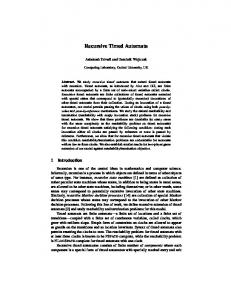
Reachability is one of the most common properties being checked by verifiers. There are two kinds of search strategies for reachability analysis during state space exploration: forward and backward search. Currently our tool uses the forward search technique. The forward analysis of the reachable configurations starts from the initial state (l0 , v0 ). Whenever allowed by the invariant of l0 , time delays can form the 1 1 → (l0 , v0 ⊕ 1) − → · · · , where v0 ⊕ i |= I(l0 ). For example, sequence (l0 , v0 ⊕ 0) − given A = �L, l0 , Σ, X, I, E�, let l0 ∈ L be the initial location with the invariant 1 1 1 → (l0 , 1) − → ··· − → x ≤ 106 , where x ∈ X. Then there may be a sequence: (l0 , 0) − (l0 , 106 ). Even with BDD representation for the set of states in this sequence, the frequent operations with the increasing number of reachable configurations are burdensome. To relieve this problem, here we introduce a symbolic representation for this kind of sequence. Definition 2. (Symbolic Representation of Delay Sequence) Given location l and clock valuation v, let < l, v > denote the set of states {(l, v � )|v � = v ⊕ i, where i ≥ 0, and v � |= I(l)}. Based on the maximal constant abstraction, for every x ∈ X, all the clock valuations greater than cA (x) + 1 are
200
R. Yan et al.
treated as cA (x) + 1. Therefore, though time can progress infinitely, the number of states in the delay sequence is finite. Therefore, a delay sequence (DS) generated by delay transitions from the state s = (l, v) can be denoted by < l, v >. And the number of states in < l, v > can be determined by I(l) and clock valuation v. Let A = �L, l0 , Σ, X, I, E� be a timed automaton. For a state s = (l, v) and a transition e = (l, g, σ, Y, l� ) ∈ E, where l ∈ L and v ∈ νX , post(s, e) denotes the set of states {< l� , v � > |if ∃i ∈ N+ such that v ⊕ i |= I(l) ∧ g, v � = v ⊕ i[Y := 0] and v � |= I(l� )}. Given the symbolic representation of DS, the symbolic semantics can be defined as follows. Definition 3. (Symbolic Semantics) Let A = �L, l0 , Σ, X, I, E� be a timed automaton. The symbolic semantics of A is based on the transition system �S, s0 , ��, where S = L × νX , s0 =< l0 , v0 >, and � is defined by the following rule: < l, v >�< l� , v � >, if there exist a transition (l, g, σ, Y, l� ) ∈ E and an i ∈ N+ , such that v ⊕ i |= I(l) ∧ g, v � = v ⊕ i[Y := 0] and v � |= I(l� ). Given a time automaton A = �L, l0 , Σ, X, I, E�, and a state (l, v). l is reachable in the integer semantics of A, iff it is reachable in the symbolic semantics �S, s0 , ��. l0
x=4
y:=0
y>=3 x:=0 y:=0
l1
x. Therefore, with DS representation, the size of state space can be reduced. Figure 3 shows the reduced state space. 3.2
Series of Delay Sequences
In a delay sequence, when some states satisfy the guard of a transition, the corresponding discrete transition can be taken, leading to the new states. From these
Improvements for the Symbolic Verification of Timed Automata l0 ,(1,1)
l0 ,(2,2)
l0 ,(3,3)
l0 ,(0,0)
l1 ,(10,5)
l1 ,(10,4)
l0 ,(4,4)
l1,(4,0)
l1 ,(9,5) l1 ,(8,4)
l0 ,(5,5)
l1 ,(5,1) l1 ,(7,3)
l1,(9,4) l1,(8,3) l1,(9,3)
l1,(6,2)
201
l1,(5,0)
l1,(6,1)
l0 ,(6,6) l1,(6,0)
l1,(7,2) l1 ,(7,1) l1 ,(8,2)
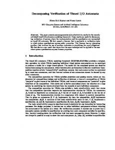
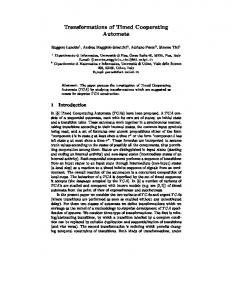
Fig. 2. Unfolded state space of the example l0 ,(0,0) l1 ,(6,0)
l1,(4,0) l1,(5,0)
Fig. 3. State space represented by DS
new states, the execution of delay or discrete transitions will be continued. For instance, in the example of Figure 1, some states in delay sequence < l0 , (0, 0) > can trigger the discrete transition from l0 to l1 . Then the corresponding successor states are (l1 , (4, 0)), (l1 , (5, 0)), (l1 , (6, 0)). After the discrete transition, only valuations of reset clocks are different from their precursors. If we ignore the reset clocks, we will find that other clock valuations in these successors still obey the rule of “⊕” operation. Then given a state generated by the discrete transition, we can compute all other new successors from the states in the same delay sequence. Let vr be the clock valuation after a discrete transition, where Y is the reset clock set. The clock valuaton of the ith state from vr is vir = vr � i, where (vr � i)(x) = � /Y vr (x) + i x ∈ . 0 x∈Y Based on this observation, we can define a coarser data structure, which comprises more than one DS. Definition 4. (Series of Delay Sequences) Let ((l, v), k, Y ) be the symbolic representation for the set of states {< l, v � > |v � = v � i, 0 ≤ i < k}. We call this representation the series of delay sequence (SDS). Let s0 = (l, v) be the so-called start state, then the SDS is denoted by (s0 , k, Y ). (s0 , k, Y ) is denoted by (s0 , 1, ∅) if Y = ∅.
202
R. Yan et al.
Then in Example 1, delay sequences < l1 , (4, 0) >, < l1 , (5, 0) >, < l1 , (6, 0) > computed from < l0 , (0, 0) > by the discrete transition can be represented by ((l1 , (4, 0)), 3, {y}). The state space is further reduced. 3.3
Reachability Analysis
During the forward search of the reachable configurations in integer semantics, we use DS to compute the successors and record the set of visited states. Given a DS t, the process for successor computation from t is: the delay sequence from t can trigger the discrete transition e when some states in the sequence satisfy its guard. Then the set of new configurations is computed. In other words, if t is not in P the set of visited configurations, then by the discrete transition e, the delay sequence from t can generate the set of configurations T = post(s, e). And the new successors will be added to the waiting list W for the computation loop. The verification will stop when W is empty or the property is satisfied. Because the structure of a DS is similar to that of a discrete state, to save the memory consumption during the verification process, we use BDD to represent the set of reachable DSs. The generalized algorithm for reachable analysis is as follows: 1: 2: 3: 4: 5: 6: 7: 8: 9: 10: 11: 12: 13: 14: 15: 16: 17: 18: 19:
Reachability() W = {< l0 , v0 >}; while W �= ∅ do get s =< l, v > from W ; if s ∈ P then continue end if for all e ∈ {(l, g, σ, Y, l� )} do T = post(s, e); if ∃t ∈ T, t |= φ then return true end if if T � W then W =W ∪T end if P = P ∪ {s}; end for end while return f alse
3.4
The Application of SDS
Because the result of post(s, e) is a set of interrelated DSs, we can use SDS to represent the set of DSs. Then W can be organized as the list of SDSs to reduce the occupied memory during the verification process. Meanwhile, time
Improvements for the Symbolic Verification of Timed Automata
203
consumption for computing new reachable configurations from DSs in the same SDS can be saved for their interrelation. To explain how to compute successors for a SDS, we firstly show the corresponding computation for a DS. Then we discuss the relation between two SDSs with the same locations. Finally we present the SDS-based reachability analysis algorithm. 3.4.1 Successor Computation for DS Given a timed automaton A = �L, l0 , Σ, X, I, E�, a state (l, v) and e = (l, g, σ, Z, l� ) ∈ E, where l ∈ L and v ∈ νX . To compute the successors, we need to consider the constraints involving I(l) and g. That is, to trigger the discrete transition, the states should satisfy the constraint I(l) ∧ g. v = max{ cA (x) − For convenience, given a clock valuation v ∈ νX , let θX v(x)|x ∈ X}. Given a constraint φ, we define – – – – –
Xφ is�the set of all clock variables occuring in φ. φl = �{x ≤ c|x ≤ c is in φ}. φg = {x ≥ c|x ≥ c is in φ}. cφ is the maximal constant occuring in φ. cφ (x) be the maximal constant compared with x in φ.
In the following computation, for constraint ϕ = I(l) ∧ g, let m = max{{cϕg (x) − v(x)|x ∈ Xϕg }, 0}
(1)
v n = min{{cϕl (x) − v(x)|x ∈ Xϕl }, θX }
(2)
Then in the delay sequence < l, v >, set of states {(l, v ⊕ j)|j ∈ [m, n]} can take the discrete transition e = (l, g, σ, Z, l� ). Example 2. For the timed automaton in Figure 1, given the initial state (l0 , (0, 0)) v and the discrete transition from l0 to l1 . Firstly, θX = 10 and ϕ = x ≥ 4 ∧ x ≤ 6. According to the definition, we get that ϕl = x ≤ 6, cϕl (x) = 6, ϕg = x ≥ 4, and cϕg (x) = 4. Then m = 4 and n = 6, the set {(l0 , (4, 4)), (l0 , (5, 5)), (l0 , (6, 6))} in < l0 , (0, 0) > can take the discrete transition from l0 to l1 . Therefore, to get successors from a DS, we have to consider the computation and judgement between clock valuations and constraints. 3.4.2 Successor Computation for SDS If all successors of DSs in a SDS can be computed according to the successors of one DS, the effort can be saved by avoiding the repeated computation between clock valuations and constraints. Given a SDS d = ((l, v), k, Y ) and e = (l, g, σ, Z, l� ), we have observed that v(x) ⊕ i = v(x) � i for all x ∈ X − Y . So some states in the ith delay sequence < l, v � i > and the delay sequence < l, v > may have same valuations except for the clocks in Y .
204
R. Yan et al.
With this observation, we discuss the corresponding process for computing new configurations. We firstly determine the set of states that can trigger the discrete transition for the start state (l, v). For the constraint ϕ and SDS d, let a1 = max{{cϕg (x) − v(x)|x ∈ Y ∩ Xϕg }, 0}
(3)
b1 = min{{cϕl (x) − v(x)|x ∈ Y ∩ Xϕl }, θYv }
(4)
a2 = max{{cϕg (x) − v(x)|x ∈ (X − Y ) ∩ Xϕg }, 0}
(5)
v b2 = min{{cϕl (x) − v(x)|x ∈ (X − Y ) ∩ Xϕl }, θ(X−Y )}
(6)
Then m = max{a1 , a2 }, and ⎧ max{b1 , b2 } ⎪ ⎪ ⎨ b2 n= b1 ⎪ ⎪ ⎩ min{b1 , b2 }
if if if if
Xϕ l = ∅ (Xϕl ∩ Y ) = ∅ . (Xϕl ∩ X − Y ) = ∅ (Xϕl ∩ Y ) �= ∅ ∧ (Xϕl ∩ X − Y ) �= ∅
Set of states {(l, v ⊕ j)|j ∈ [m, n]} in the delay sequence < l, v > can trigger the discrete transition e = (l, g, σ, Z, l� ). Example 3. Now we use SDS ((l1 , (4, 0)), 3, {y}) and the transition from l1 to l0 in Figure 1 as the example. For the start state (l1 , (4, 0)) and guard y ≥ 3 in the transition, we get that ϕ = x ≤ 10 ∧ y ≤ 5 ∧ y ≥ 3. According to the Equation 3 ∼ 6, a1 = 3, b1 = 5, a2 = 0, and b2 = 6 respectively. Because Xϕl = {x, y} and Y = {y}, neither Xϕl ∩ Y nor Xϕl ∩ X − Y is empty. Therefore m = 3, n = 5, the set of states {(l1 , (4, 0) ⊕ j)|j ∈ [3, 5]} in the delay sequence < l1 , (4, 0) > can take the discrete transition. After the computation for the successors of the start state in SDS, we can get the set of successors from other DSs in the same SDS according to the feature of SDS. For the delay sequence of < l, v � i > where 0 ≤ i < k, m = max{a1 , a2 − i}, and ⎧ max{b1 , b2 } if Xϕl = ∅ ⎪ ⎪ ⎨ max{b2 − i, 0} if (Xϕl ∩ Y ) = ∅ n= , if (Xϕl ∩ X − Y ) = ∅ ⎪ b1 ⎪ ⎩ min{b1 , max{b2 − i, 0}} if (Xϕl ∩ Y ) �= ∅ ∧ (Xϕl ∩ X − Y ) �= ∅ states that can trigger the discrete transition e are the set {(l, (v � i) ⊕ j)|j ∈ [m, n]}. Example 4. For SDS ((l1 , (4, 0)), 3, {y}), we have obtained that a1 = 3, b1 = 5, a2 = 0, and b2 = 6. Then
Improvements for the Symbolic Verification of Timed Automata
205
1. For the delay sequence < l1 , (4, 0)�1 >, set of states {(l1 , (5, 0)⊕j)|j ∈ [3, 5]} can trigger the discrete transition. 2. For the delay sequence < l1 , (4, 0)�2 >, set of states {(l1 , (6, 0)⊕j)|j ∈ [3, 4]} can trigger the discrete transition. 3.4.3 SDS-Based Reachability Analysis The following is the reachability analysis algorithm by the application of SDS. 1: 2: 3: 4: 5: 6: 7: 8: 9: 10: 11: 12: 13: 14: 15: 16: 17: 18: 19: 20: 21: 22: 23: 24: 25: 26: 27: 28: 29: 30:
ReachabilitySDS SDS d� ; stack of SDS W ; W.push((l0 , v0 ), 1, ∅); while W �= ∅ do get d = (s0 , k, Y ) from W ; for all e = (l, g, σ, Y � , l� ) enabled at d do SuccessorN (a1 , b1 , a2 , b2 , d, e); for i = 0; i < k; i + + do si = s0 � i; if si ∈ P then continue end if distance = getdistance(i, ϕ, a1, b1 , a2 , b2 ); if distance < 0 then break end if s� = (l� , (si .v ⊕ max{a1 , a2 − i})[Y � := 0]); d� = (s� , distance + 1, Y � ); if ∃s ∈ d� , s |= φ then return true end if if d� ∈ / W then W.push(d� ) end if P = P ∪ {si }; end for end for end while return f alse
Line 8 SuccessorN computes the related ranges for the start state according to the certain discrete transition. Line 9-27 compute all the successors of d, and Line 13 getdistance is to get the number of states in every DS which is capable of taking the discrete transition (the number of successors for every DS). Then Line 18, 19 generate a new set of DSs.
206
3.5
R. Yan et al.
Inclusion Relation of SDS
When we get a new set of reachable configurations, we need to judge its relation with those SDSs in W to avoid the repeated computation and ensure the termination of checking. The relation between the new set d� and d ∈ W is: – equivalence, if their start states, the number of DSs, and the set of reset clocks are equal, which is a special case of inclusion. Or – intersection, if two sets of reset clocks are equal, and there exists 0 ≤ i < k, 0 ≤ j < k � , such that all the valuations of s0 � i and s�0 � j are the same state. Or – irrelevance, neither with equivalence nor intersection relation. The algorithm for judging SDS relations is as follows. The idea of the algorithm is: firstly we should judge whether the differences between two clock valuations are the same. If some clock differences are different from others, there is no equivalence or intersection relation. If all clock valuations except for reset ones have the same difference, two SDSs may intersect, or one is a subset of the other. 1: 2: 3: 4: 5: 6: 7: 8: 9: 10: 11: 12: 13: 14: 15: 16:
4
SDSRelation(d, d� ) select an x which x ∈ / Y ∧ s0 (x) < cA (x) ∧ s�0 (x) < cA (x); � diff=s0 (x) − s0 (x); for all x ∈ X − Y do if s0 (x) − s�0 (x) �= diff then return irrelevance end if end for if diff ≤ 0 ∧ diff + k ≥ k � then return d ⊇ d� else if diff ≥ 0 ∧ diff + k ≤ k � then return d ⊆ d� end if end if return intersection
Experiments
Based on the symbolic data structure, we have implemented a prototype to support the verification of real-time systems with multi-processes, synchronizations, and broadcasts. The tool is available at http://lcs.ios.ac.cn/∼ligy/tools/. We compare the experiment results with those of Rabbit. All experiments were performed on a 2.6GHz Pentium 4 with 512MB of memory. And experiments were limited to 30 minutes of CPU time.
Improvements for the Symbolic Verification of Timed Automata k=0 x:=0
idle
207
request x=b,k!=id critical
waiting x>=b,k=id
Fig. 4. Fischer’s mutual exclusive protocol
init
send x:=0
busy transm x>= σ
begin begin x:=0
cd! x:=0 cd x