International Journal of Applied Engineering Research ISSN 0973-4562 Volume 9, Number 22 (2014) pp. 15309-15319 © Research India Publications http://www.ripublication.com
Improving Disparity Map of A Specific Object in A Stereo Image Using Camera Calibration, Image Rectification, and Object Segmentation Hermawan Syahputra1*, AgusHarjoko2, Retantyo Wardoyo2, Reza Pulungan2 1
Department of Mathematics, Faculty of Mathematics and Natural Sciences,State University of Medan, Medan, Indonesia 2 Department of Computer Science and Electronics, Faculty of Mathematics and Natural Sciences, Universitas GadjahMada, Yogyakarta, Indonesia *Tel. +6281375040550; e-mail:
[email protected] Abstract The objective of the study was to improve the disparity map of a certain object in a stereo image. The steps required to complete this are first, to perform camera calibration in order to extract camera parameters, and then to use these parameters to rectify the stereo image. Second, to perform segmentation to separate the object from the background of the image. Separation of the object from the background was performed to produce a good disparity for the object. This had not been done in previous studies. Using segmentation, bias and error of stereo correspondence had been reduced, since the correspondence was focus on the intensity of the left and right objects in the stereo image. Using rectified and segmented stereo images, better disparity maps had been obtained. Keywords: Disparity map, image rectification, camera calibration, segmentation object, stereo image.
Introduction Vision provides a very important meaning for human beings. Stereo vision is a reliable tool to find the depth of a scene. Stereo vision has been proved to provide an extraordinary result in estimating the disparity map or the depth[1].Stereo vision is the process of transforming the information from two areas of images into a 3D description of a scene and then finding depth information in terms of the proper distance. With the information depth, one can make a model of an area and other
Paper Code:
15310
Hermawan Syahputra et. al
natural environments; and this model can be used in a variety of applications, from virtual reality, flight and robot simulation, to feature extraction and navigation [2,3]. In addition, in stereo vision applications, especially in 3D reconstructions with disparity, both intrinsic and extrinsic parameters of the camera should be obtained in the beginning. The accuracy of the 3D reconstruction data depends on the accuracy of the disparity, the calibration of stereo system, image rectification, and the overall construction of the stereo system [3]. Several previous studies have developed the estimation of the disparity map, including the disparity estimation on a particular object [4]. The disparity map estimation of stereo images is also performed by using a hybrid method, i.e., a combination of belief propagation and mean shift [5]. The disparity map estimation that uses the back propagation and pyramid segmentation, which divides images into several segments, has also been proposed [6]. In this research, a segmentation step is added to focus on a particular object in the image and to ignore the background. Therefore, the presence of the segmentation and the rectification should quicken the matching process and reduce the intensity bias between the object and its background.To get an accurate disparity map, rectification and good preprocessing are required. Besides, to reduce the focus on an object in the image, the preprocessing and image segmentation are required. Segmentation produces images displaying objects on white backgrounds. With the construction process of this stereo system, the resulting accuracy of the disparity map and the depth is expected to improve.
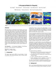
Materials and Method The proposed model in this study is illustrated in Figure 1.
Left image Right image
Rectification of left and right images
Segmentation of left and right images
Disparity map
Camera calibration Figure 1. The proposed model of the disparity map computation The proposed model consists in the following steps: first, the left and right images are taken using a stereo camera. Then, each image is corrected by using both the intrinsic and extrinsic parameters of the camera obtained from the calibration process. The rectified left and right images are then segmented to obtain the object of interest in the image. Finally, the rectified and already segmented left and right
Improving Disparity Map of A Specific Object in A Stereo Image
15311
images are used to determine the disparity map. For detail proposed model can be described as following step.
Input of Stereo Images The input of proposed model were left and right images (Figure 1). The images was captured using FujiFinepix W3 3D stereo camera. The camera have a two lenses 10 MP, and resolution until 3584 x 2016pixel. Camera Calibration In this research, the first step was to calibrate the camera.Zang[7] explained that camera calibration is a process of finding the intrinsic and extrinsic parameters of a camera or a subset of these. A camera is usually described using the pinhole model.A camera model consists of a set of intrinsic parameters that determine how the camera forms images, and a set of extrinsic parameters that determine the position and direction of the camera in the world.The image of a 3D point M = [X; Y; Z]T, denoted by m = [u; v]T is formed by an optical ray from M passing through the optical center C and intersecting the image plane. The three points M, m, and C are collinear. We use to denote the augmented vector by adding 1 as the last element: =[u; v; 1]T and = [X; Y; Z; 1]T . The relationship between the 3D point M and its image projection m is given by (1) with and where (R; t), called the extrinsic parameters, is the rotation and translation which relates the world coordinate system to the camera coordinate system, and A is called the camera intrinsic matrix, with (u0; v0) the coordinates of the principal point, and the scale factors in image u and v axes, and the parameter describing the skew of the two image axes. The 3 x 4 matrix P is called the camera projection matrix, which mixes both intrinsic and extrinsic parameters. After the camera’s perspective projection matrix P is obtained, the intrinsic and extrinsic parameters of the camera can be uniquely determined. First, by denoting the submatrix 3x3 of P by B and the last column of P by b, i.e., P= [B | b]. Since P = A[R | t], we obtain: B = AR and b = At (2) Once the intrinsic parameters or the equivalent matrix A is known, the extrinsic parameters can be determined from Equation (2) as: and Images Rectification
(3)
15312
Hermawan Syahputra et. al
The second step is to rectify the stereo image. Once the intrinsic and extrinsic parameters of the camera have been resulted using the camera calibration, then these parameters are used to rectify the image. Images rectification was performed by using the concept of epipolar geometry [8]. Stereo image rectification is a process of image transformations in such a way that the corresponding epipolar lines in all images become collinear with each other and with the image scanning lines. In rectified images all optical axes are parallel as well. The other interesting feature inherent to the rectified stereo system is a shift of the epipoles to infinity. Thus, rectification of images can be thought of as a process of changing positions of epipoles to infinity. The rectification process is limited to the search for the transformation of the planes Πl0 and Πr0 to the planes Πl1 and Πr1, respectively (Figure 2). The transformation sought can be described as a composition of the following transformations [8]. 1. Rotation of the left and right camera planes in such a way that the epipoles go to infinity (and thus the epipolar lines become parallel). This rotation is described by a rotation matrix Q. 2. Rotation of the right camera according to the transformation described by a matrix R from Pr = R(Pl − T) where Pl and Pr are two vector that pointing at the same point P from 3D space, translation T = Or–Ol and rotation determined by an orthogonal matrix R. The matrix Q can be found by considering three mutually orthogonal unit vectors: q1, q2 and q3. The vector q1 is collinear with the translation vector T between the focus points of the two cameras and is given as (4) The vector q2 is orthogonal to the vector q1. Because [−T2, T1, 0] ・[T1, T2, T3]T= 0
(5)
thenq2 takes the form (6)
The third vector q3 has to be simultaneously orthogonal to the vectors q1 and q2. Therefore it can be set to the vector product q3 = q1 × q2. (7) The vectors q1, q2 and q3 determine the following rotation matrix Q:
In practice, to obtain integer values of coordinates in the new (i.e. rectified) camera setup, the rectification process should be performed backwards, i.e. starting
Improving Disparity Map of A Specific Object in A Stereo Image
15313
from the new coordinates and applying the inverse transformation Q−1. This way, the new intensity values in the ‘new’ system can be determined, for example, by the bilinear interpolation of the original values from the ‘old’ setup.
Figure2.Stereo image rectification. The epipolar lines become collinear and parallel to the image scanning lines [8] Fusielloet al.[9] described that positions (i.e., optical centers) of the new PPMs are the same as the old cameras, whereas the new orientation (the same for both cameras) differs from the old ones by suitable rotations, since intrinsic parameters are the same for both cameras. Therefore, the two resulting PPMs will differ only in their optical centers, and they can be thought as a single camera translated along the X-axis of its reference system. The new PPMs can be written in terms of their factorization. From Equations (2) and (3): ,
(8)
The intrinsic parameters matrix A is the same for both PPMs, and can be chosen arbitrarily. The optical centers C1 and C2 are given by the old optical centers, computed with Equation (3). The matrix R, which gives the camera's pose, is the same for both PPMs. More information on image rectification can be found in [9,10]. Segmentation The third step was to segment theobjects from the background. Segmentation is carried out to obtain the image with a white background, and to remove the noise of the image. The following stages are performed in image segmentation (see Figure 3):
15314
Hermawan Syahputra et. al
Reading and adjust the color image (acquire background color information and minimum pixels area). Converting the colored image into a black and white image and removing noises. Extracting the image boundary.
Figure 3. Stages in images segmentation The color setting is performed to improve the color difference between the background and the object. The image manipulation is performed in black and white version of the images, i.e., edge, boundaries, and so on. While converting the image from colored into black and white, if the object’s color is similar to the background, we will not be able to obtain a profile overview of the overall object. Disparity Map The final step was construct the disparity map. The disparity map is generated by using a stereo correspondence algorithm [11]. The virtue of the stereo matching algorithm can be described by using the same structure groups. The main steps are (see Figure 4): 1. The computation of the matching values for each pixel of both input images. 2. The aggregation of the computed matching values, in addition to the supporting area for each pixel of each image. 3. To find the optimum disparity value for each pixel of an image. 4. To refine the resultant disparity maps. Left and right rectified and/or segmented images as input
Matching cost calculation
Aggregation matching cost
Disparity Selection
Disparity Map
Figure4.Disparity map computation Sum of absolute intensity differences (SAD) is the simplest and most frequently used measure in the matching. SAD involves a simple subtraction and the computation of the absolute values, as follows:
whereIl, Irare intensity value of left and right images, (x, y) are pixel coordinates, W is window size and d is the disparity value.
Improving Disparity Map of A Specific Object in A Stereo Image
15315
Results and Discussion Figure 6 is the left and right images, which are captured by a Fujifilm W3 stereo camera, taken from two checkerboard patterns attached on the corner of the wall with an angle of 900 to each other. These are the images used in calibration.
Figure 5. The left and right images used in calibration The result of camera calibration based on the left and right images Camera calibration is performed on both the left and right images. The real world coordinate and image coordinate points are manually determined in advance (see Figure 6 and 7). - Calibration of the left image 20
1300 1200
15
1100 1000
10
900 800
5 20
700
15
20
600
15
10
10
5
500
5 0
0
400
0
500
1000
1500
2000
Figure 6. Coordinate points of left image on 3D and 2D plane - Calibration of the right image
2500
15316
Hermawan Syahputra et. al 1300
20 1200 1100
15 1000 900
10
800 700
5 20 15
20 15
10
10
5
5 0
600 500 400
0
0
200
400
600
800
1000
1200
1400
1600
1800
Figure7. Coordinate points of right image on 3D and 2D plane Table 1. Extrinsic and intrinsic parameters resulting from the calibration of cameras Parameters
Calibration of the right image
Calibration of the left image
0,015228 −0,02853 0,000127 0,645008 −0,006 −0,00685 −0,02988 0,762852 −5,86E − 06 −6,76E − 06 2,21E − 07 0,000492
0,015245 −0,03217 0,000101 0,527837 −0,00708 −0,00706 −0,03271 0,84791 −6,70E − 06 −6,83E − 06 3,00E − 07 0,00054
−0,75568 0,654928 0,003452 0,01875 0,016374 0,999689 −0,65466 −0,755514 0,024659
−0,71347 0,7006567 0,005895 0,02614 0,018209 0,999492 −0,70019 −0,71327 0,031307
Translation Matrix
−0,25379 −10,0607 54,98734
4.9007 −10.3723 56.3552
Scaling parameter in the direction of X Scaling parameter in the direction of Y Optical center of the image Average pixel error in the direction X Average pixel error in the direction Y
3373,920 3362,329 (1295; 935) 0,0025 -0,00026
3490,079 3447,735 (1281,78, 936,94) 0,00123 0,0088
Calibration Matrix
Rotation Matrix
Image rectification The resulting image obtained after the rectification performed on the left and right images can be seen in Figure 8.
Improving Disparity Map of A Specific Object in A Stereo Image Left image
Right image
100
100
200
200
300
300
400
400
500
100 200 300 400 500
500
Rectified left image
100 200 300 400 500 Rectified right image
100
100
200
200
300
300
400
400
500
500 100 200 300 400 500
15317
100 200 300 400 500
Figure 8. Before and after rectification Segmentation of the left and right images The results obtained after image segmentation on the left and right images can be seen in Figure 9.
(a)
(b)
Figure 9. Segmentation (a) image segmentation of left rectified image, (b) image segmentation of left rectified image Disparity of the stereo image The disparity map is obtained by using the SAD (Sum Absolute Difference) matching algorithm. In this algorithm, the setting is done by adjusting the window value w=3x3 and the maximum disparity dmax=7. The results of several experiments
15318
Hermawan Syahputra et. al
to obtain the disparity map of stereo images can be seen in the Figure 10. 7
7
6
50
6
50
5 100
5 100
4 150
4 150
3 200 2 250
300
50
100
150
200
250
300
3 200 2
1
250
0
300
(a) Unrectified and segmented
1
50
100
150
200
250
(b) Rectified and unsegmented 7
7
6
50
0
300
6
50
5
5
100
100
4
4
150
150 3 200
3 200
2 250
1
300
50
100
150
200
250
300
(c) Unrectified and segmented
0
2 250
300
1
50
100
150
200
250
300
0
(d) Rectified and segmented
Figure 10. Segmentation and rectification
Discussion Based on Figure 10, it can be shown that visually, the disparity map resulted from segmentation andunrectification gives better results than those unsegmentation and rectification. Meanwhile, the disparity results obtained by using image rectification do not provide better results than those obtained by using images without rectification. It means that the original images without rectification produced by stereo cameras do not undergo significant distortion or significant shifts. Finally, the disparity results will look better than previous researches such as San Yong and Hon [4],Kamencay et al.[5,11], Baha and Larabi [6]if the segmentation is performed on both images, the left and right image.This is due to the presence of the segmentation and rectification that can reduce the matching process and reduce the intensity bias between the objects of which background will be recognized. Therefore, the new schame of disparity map calculation based on images rectification and segmentation provided better but not optimum result, so for future work, the schame is necessary to develop in the future by taking the smoothing or post processing of original images or disparity map resulted.
Conclusion
Improving Disparity Map of A Specific Object in A Stereo Image
15319
In this paper, we had done images rectification and segmentation to improve quality of disparity maps an object in the stereo images. Images rectification and segmentation is required to reduce the complexity of the computation for the left and right correspondences of pixel images. For images rectification, camera calibration will be done earlier. The experimental results show that visually, the disparity map resulted from images rectified gives better results than those unrectified. Furthermore, the disparity map results show a better appearance by conducting left and right image segmentation beforehand.The disparity map is obtained by using the SAD (Sum Absolute Difference) matching algorithm. In this algorithm, the setting is done by adjusting the window value w=3x3 and the maximum disparity dmax=7.
Reference [1] Malik, A. S., Choi, T. S., Nisar, H. & Global, I, 2012.Depth map and 3D imaging applications: Algorithms and technologies:Information Science Reference. [2] Islam, M. S., Hannan, M. & Basri, H., 2012. An Application of Stereo Matching Algorithm for Waste Bin Level Estimation. Journal of Asian Scientific Research, 2(11): 731-736. [3] Lipnickas, A. & Knyš, A., 2009. A Stereovision System for 3-D Perception. Electronics & Electrical Engineering, 3(91): 99-102. [4] San Yong, Y. & Hon, H. W., 2008. Disparity Estimation for Objects of Interest. Proceedings of World Academy of Science: Engineering & Technology, 45(19): 533-536. [5] Kamencay, P., Breznan, M., Jarina, R., Lukac, P. & Zachariasova, M., 2012a. Improved Depth Map Estimation from Stereo Images Based on Hybrid Method. Radioengineering, 21(1): 70-78. [6] Baha, N. & Larabi, S., 2012. Neural Disparity Map Estimation from Stereo Image. International Arab Journal of Information Technology (IAJIT), 9(3): 217-224. [7] Zang, Z., 2004.Emerging Topics in Computer Vision:Prentice Hall Profesional Technical Reference [8] Cyganek, B. & J., P. S., 2009.An Introduction to 3D Computer Vision Techniques and Algorithms:John Wiley & Sons, Ltd. [9] Fusiello, A., Trucco, E. & Verri, A., 2000. A compact algorithm for rectification of stereo pairs. Machine Vision and Applications, 12(1): 16-22. [10] Shimizu, M. & Okutomi, M. (Year) Calibration and rectification for reflection stereo. In: Computer Vision and Pattern Recognition, 2008. CVPR 2008. IEEE Conference on, 2008. IEEE, 1-8. [11] Kamencay, P., Zachariasova, M., Breznan, M., Jarina, R., Hudec, R., Benco, M. & Matuska, S., 2012b. A New Approach for Disparity Map Estimation from Stereo Image Sequences using Hybrid Segmentation Algorithm. International Journal of Modern Engineering Research (IJMER), 2(5): 3201-3206.