football in the RoboCup Middle Size League, and was used without modifications. .... for the coefficients k1, k2 and k3 were computed empirically by training.
Robieeta: a Robotic Football Player in Autonomous Driving Artur Pereira*, Bernardo Cunha*, Jose Luis Azevedo*, Pedro Pratat, Joao Silvat, Flavio Netot, Pedro Caetanot and Hugo Reist *Instituto de Engenharia Electr6nica e Telematica de Aveiro (IEETA) Universidade de Aveiro, Aveiro, Portugal Email: {artur, mbc, jla}lieeta.pt tDepartamento de Electr6nica e Telecomunicacoes Universidade de Aveiro, Aveiro, Portugal Abstract- This paper describes the work undertaken, in a twoweeks time, to put a robotic football player doing autonomous driving in a robotics contest. The robot was designed to play football in the RoboCup Middle Size League, and was used without modifications. During competition, it has to complete two laps of a circuit, autonomously, as fast as possible, and without incurring into infractions. The sensory system was mainly based upon two webcams, one allowing for omnidirectional vision and the other directed to the robot front.
I. INTRODUCTION
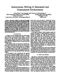
The IEETA's ATRI working group, through the CAMBADA project [1], has been developing, since 2003, a robotic football team to participate in the RoboCup Middle Size League [2]. It is a competition between teams of autonomous robots, used as a way to encourage research in autonomous and collaborative behavior in robotics. The robots of the CAMBADA team [3] (see figure 1) have a cylindrical body, 40 cm wide and approximately 80 cm height. The locomotion system is supported by 3 independent wheels, assembled in such a way that allow robot movement in any direction. The sensory system is basically composed of two webcams, one allowing for omnidirectional vision, while the other is directed to the front of the robot.
carrying on in Portugal in the field of robotics. One of those activities is a competition, called autonomous driving, where robots have to drive autonomously in a closed circuit. There is a great compliance of the CAMBADA robot to the autonomous driving competition. First of all it is a competition for autonomous robots. Then, the lane is 90 cm wide, which fits nicely in the robot diameter. Finally, the sensory elements of the robot, vision and hodometry, are enough to keep it on lane. Thus, the autonomous driving competition appears as a good stage to validate the robot capabilities. The challenge that the authors propose to themselves were to participate without changing anything in the robot hardware, hence, without adding any sensory element. The challenge was profit: the third place was one of the rewards. The remaining of the paper is organized as follows. In section II the autonomous driving competition is described. In sections III and IV the robot player, starting point of the developed work, is presented. Sections V and VI are devoted to the developed software: first the basic behaviors and then the main algorithm. Finally, section VII concludes the paper presenting results and conclusions. II. AUTONOMOUS DRIVING
Fig. 1. A view of the CAMBADA football player.
The Festival Nacional de Robtica [4], which in 2005 had its 5th edition, is a contest bringing together different activities
The autonomous driving contest is a medium complexity technical challenge, where a mobile robot has to autonomously drive in a closed circuit in a way similar to normal car driving. The track used in the Robtica'2005 autonomous driving competition (see figure 2) has the shape of an eight (8) and is delimited by two white lines. There is a crosswalk in the middle, controlled by a pair of light panels, one in each direction. The challenge unfolds into 3 rounds. In all of them, robots must autonomously drive in a black lane delimited by white lines, having a crosswalk in the middle. The robot starts from a position immediately before the crosswalk and finishes stopping in the same point after 2 laps. Things change from round to round. In the first, robots have just to complete the two laps to the circuit following the path they most prefer, as far as possible. There are time penalties if robots, during their driving, cross the delimiting lines.
242
0-7803-9365-1/05/$17.00c2005 IEEE
Fig. 2. Robtica 2005 autonomous driving circuit.
In the second round two light signaling panels are added, just before the crosswalk, one in each direction. They supply instructions to the robots that must be observed. There are 3 different instructions signals: a red cross, a vertical green arrow and a left yellow arrow. The first tells the robot to stop immediately before the crosswalk. The green and yellow arrows define the path to follow after crossing the crosswalk. Actually there are two more possible patterns in the light panels: a green and red chessboard, indicating the competition is finishing, and a right yellow arrow, instructing the robot to park. In this round robots must complete the two laps, while observing light instructions. In the third and last round a tunnel and a roadworks area are added. The tunnel have white interior walls and is positioned as shown in figure 2. Inside the tunnel the white lines delimiting the lane do not exist. The roadworks area is a detour on the circuit lane marked with yellow pins. The competitor can decide to compete without the roadworks area, assuming in that case a corresponding penalty.
Control of movement is achieved by 4 computational modules, based on a micro-controller and interconnected by a CAN network. A central module receives orders from some higher level software and decomposes them into orders to each one of the wheels. These are sent to the other 3 modules, each responsible for a wheel. A feedback system based on hodometry data collected from each wheel guarantees a good execution of a required movement order. Movement orders appear in the form of speeds. An order is a vector v = (vx vy vo), where (vx,vy) represents the linear component and vo the angular one. It is also possible to define the transition mode between consecutive movement orders: smooth and abrupt. In the second mode the robot tries to quickly change from a speed vector to the other, which can cause some instability. Hodometric data can be retrieved in the form of the triple (x, y, 0), where (x, y) represents the spacial position of the robot center and 0 its angular orientation. Based on the wheels movement, these values are being updated by the central computational module. At any time the higher level software can set/reset their values in order to do calibration. IV. ROBOT VISION SYSTEM
The robot locomotion system [5] is composed of 3 independent wheels assembled as shown in figure 3. The wheels are special in that they can transversely slip without friction. The placement and characteristics of the wheels, along with an appropriated control algorithm, allow for the total control of robot movement. For instance, it is possible to put the robot moving in a straight line while rotating along its vertical axis.
The robot vision system is composed of two webcams, one omnidirectional and another directed towards the robot's front. The first one is fitted along with the vertical axis, turned down. This way the robot has omnidirectional vision in its vicinity, roughly 1 meter around robot centre. Figure 4 shows an image of a lane segment caught by this camera. The image shows a useless zone and 3 possible interference points. In the central part it is seen the own robot, which is not useful in terms of driving. It must be ignored or filtered out. The robot physical structure create 3 points of possible intersection with the white delimiter lines, which can interfere with detection mechanisms. This is visible in the image in two points. The camera lenses introduce distortion that we must be aware of. In the image, what actually are two parallel white lines appear to be closer in the top and bottom than in the middle. Thus, computation of distances between elements from an image of the omnidirectional camera must take this distortion into consideration. This is done through a direct conversion from an image pixel to the corresponding point in the ground.
Fig. 3. The robot locomotion system.
Fig. 4. An image from the omnidirectional camera.
III. ROBOT LOCOMOTION SYSTEM
243
It is implemented by an R x C matrix, where R and C are the image dimensions. In order to save time, the matrix was filled using interpolation and replication. Only a quarter was computed. In one side, it is assumed that the image plan is parallel to the ground. In the other side, it is assumed that lens distortion is equal in the 4 quadrants. For the precision levels required both assumptions are valid. To fill the quadrant, first some pixels are chosen and the corresponding ground points measured; then using interpolation the other points are computed.
The second camera is fitted in the robot front, partially turned down. This way it covers a region from the near ground to the horizon. In terms of our autonomous driving challenge this camera was used to crosswalk detection and light signal identification. It was not necessary to correct its distortion. V. BASIC ACTIONS The driving process is supported by a set of basic software elements that were developed, tested, and then integrated in the main algorithm. This set includes: lane tracking, crosswalk detection, crosswalk stoppage, light signal identification,
tunnel detection, and parking. The work has benefitted from experience got from participation in other robotic competitions (see for instance [6]).
A. Lane Tracking Lane tracking is the most important action of the driving process. Except for short periods of time, when it is stopped looking to the light panel, the robot is driving, following a trail that keep itself in lane. Lane tracking is implemented by a closed control loop, based on a PD (proportional and derivative) controller. Its global diagram is depicted in figure 5.
0, 0
(3
v
Vy
,
d, 0 Roo Image/hodometry
D Fig. 5. Diagram of the lane tracking control loop.
Robot movement is based on frontal (vy) and angular (vo) speeds. The frontal speed is used to make the robot going on. The angular speed is used to correct robot position in order to keep itself in the desired trail. The idea is to put the robot following a trail coincident with the lane axis. Thus, the equilibrium point, represented by the 0, 0 in figure, corresponds to have the robot exactly over the lane axis and aligned along it.
(a)
(b)
Fig. 6. Different scenarios to compute robot deviations.
Block D is responsible to collect sensory data from the robot image or hodometry and determine its real position in relation to the balance point. This position is given by two values, a transverse and an angular deviation to the lane axis. Any deviation is compensated by block C, computing an angular speed that pushes robot to equilibrium. The angular speed at instant i, (vo)i, is given by expression
(Vo)i = k1di+k2(di -di-)+k3*Oi where di e di 1 are the transverse deviations at instants i and i1 and Oi is the angular deviation at instant i. Suitable values for the coefficients k1, k2 and k3 were computed empirically by training. We verify that they depend on robot weight and speed. Thus, a set of coefficient values were determined for each front speed we intended to use. Whenever the frontal speed changes the coefficients must change accordingly. Computation of transverse and angular deviations is done in different ways depending on robot situations. The most frequent case is illustrated in figure 6.a. The robot moves freely, in the sense that there is no disturbing elements in front. Deviations are measured by processing two rows of the image acquired by the omnidirectional camera. The rows are scanned out from center looking for the white delimiter lines. The use of two rows allows for estimations of the two deviations, transverse and angular. The scanning is done from center to right or from center to left depending on the absence of delimiter lines or on lane curvature. If the lane curves to the left, scanning is done to the right. When the robot is approaching the crosswalk, deviations can not be computed using the previous method. The white color from the crosswalk can interfere with the scanning. This is illustrated in figure 6.b. In this cases scanning is done on an image row took at the rear of the robot. Once the delimiter white line is found, it is tracked towards the robot front until the points corresponding to the front image rows are reached. This way the same expressions can be used to compute deviations. One must note that using scanning rows to the rear is not a good idea. On one side, the robot moves towards the front rows and thus moving away the rear ones. That is, the front rows represent positions the robot will eventually reach in near future if its vector speed is not changed. On the other side, if the robot is approaching a curve the front rows produce an estimation of the deviations that foster the movement, while the rear rows can be counterproductive.
244
When robot is passing through the crosswalk both the previous methods can lead to undesired results, because of interference due to white from the crosswalk. In this case one take advantage of hodometry data and use it to estimate deviations. It is known that hodometry can only be reliably used in the short term, because of the cumulative nature of the errors. Thus, we only use hodometry until it is safe to apply again the first method.
Transition: if signal is red stay in same state; otherwise memorize signal and go to state 1. state 1: turn left in order to aligned robot along with lane. (Due to front camera position the robot must turn right 45 degrees to see the light panel.) Action: apply rotational speed to robot. Transition: if robot is aligned go to state 2; otherwise stay in same state. state 2: going ahead while crossing the crosswalk. B. Crosswalk, Light Panels and Tunnel Action: (1) compute and apply front speed, using hodomCrosswalk detection is done using images from the frontal etry to evaluate deviations; (2) evaluate end of crosswalk. camera. Due to lack of developing time a simple approach was Transition: if crosswalk has gone go to state 3; otherwise followed, that, luckily, got approved. A window was defined stay in same state. on the image and we have decided that a white concentration state 3: choose direction to follow. above a given threshold in that window should be interpreted Action: do nothing. as the crosswalk. From the position of the window we estimate Transition: if (memorized) signal is green (go ahead), go the crosswalk position in terms of robot coordinates. to state 4A; otherwise signal is yellow (turn left) Light signals are identified using also images from the go to state 4B. front camera. Since the three main signals, stop, go ahead state 4A: go ahead tracking the delimiter line to the right, and turn left have different colors, we can rely on color until the crosswalk appears again in front of robot. analysis on an image window to make identification. Again, Action: (1) compute and apply front speed, using omni a color concentration above a given value is assumed as the camera image to evaluate deviations evaluation is done corresponding signal. As noted before the turn right signal, scanning image rows from the front of the robot; (2) the instruction to park, does not interfere with identification, evaluate presence of the crosswalk. because it can only appear at the competition end. Transition: if crosswalk is detected, go to state 5A; The tunnel received little specific processing. In terms of otherwise stay in same state. driving nothing was done. The delimiter white lines are absent state 5A: go ahead tracking the delimiter line to the right, but the interior walls are white. Thus, we just assume the until reach the crosswalk. lane is wider. The white walls do interfere with crosswalk Action: (1) compute and apply front speed, using omni detection, since it can produce a high white concentration on camera image to evaluate deviations evaluation is done the crosswalk detection window. In this case we use hodometry scanning image rows from the rear of the robot; (2) to discriminate. evaluate closeness to the crosswalk. Transition: if close to the crosswalk, go to state 6; VI. MAIN ALGORITHM otherwise stay in same state. The main algorithm is implemented as a control loop, whose state 6: stop in crosswalk. period is determined by the reading of images from the two Action: stop robot. cameras. (These have been configured to operate at a frame Transition: if last lap, goto state 8; otherwise go to state 7. rate of 30 fps, the maximum allowable.) It corresponds to a state 7: turn right in order to face light panel. Moore state machine where: Action: apply rotational speed to robot. * States represent types of robot behaviors. For instance, a Transition: if robot is facing light panel, go to state 0; robot is running tracking the delimiter line on the right otherwise stay in same state. side and scanning image rows from the front. state 8: park. * Transitions are labelled with the events that cause change Action: apply parking instructions. in robot state. For instance, the signal go ahead cause States 4B and 5B, not shown above, as similar to states 4A transition from state waiting for the light panel change and 5A but use the left delimiting white line to control movestate to state running tracking the delimiter line on ... ment. Parking is done as a sequence of predefined instructions, . Actions correspond to robot speed computation and set- since it is known where the robot stops after the last lap and ting. where the parking area is. The used state machine differs from round to round, since the VII. RESULTS AND CONCLUSIONS elements into play are different: the light panels only appear in the second round and the tunnel in the third. It follows The Rob6tica'2005 autonomous driving contest appeared a simplified version of the control loop used in the second as a good environment to test the robots developed for the round. CAMBADA football team. One of these robots participated in state 0: keep stopped in start position, waiting for a go that competition without any modification, thus without adding ahead or turn left signal in light panel. or modifying any sensory element. The hardware vision and Action: evaluate light panel signal. hodometry proved to be enough to develop and implement
245
a control algorithm to transform the robot in an acceptable autonomous vehicle. The global results were satisfactory: a third place among 17 competitors. Two different results must be pointed out from the experience. In one side, it was shown that a robot developed for a given purpose can be used in a different one. A robotic football player was successfully used as an autonomous vehicle. In the other side, the participation in the contest was used to test the hardware of the robot. Vision from the omnidirectional camera was sufficient to control driving of the robot, except for crosswalk vicitiny, where the white color of the crosswalk interferes with the white color of the delimiting lines. Vision from the directional camera was only used to detect the crosswalk and recognize light panel signals. Hodometry, as expected, showed to be reliable only in the short term, with the angular orientation being more reliable than the spacial position. After a complete lap to the circuit, the error in the spacial position was about half a meter, while the error in the angular orientation was just a few degrees. That's why we only used hodometry for a small segment of the path: while crossing the crosswalk, where the other driving control methods can not be used. Actually, in the third round, we also used hodometry to decide when the robot is approaching the tunnel. Is this case, we only need a rough localization of the tunnel and so the hodometry error is acceptable. ACKNOWLEDGEMENTS To the CAMBADA team we acknowledge the availability of a robot. To the Instituto de Engenharia Electmica e Telemtica de Aveiro (IEETA) we acknowledge the sponsoring of contest
participation.
REFERENCES [1] (2004) The CAMBADA Project Website.
[2]
[3] [4] [5]
[6]
[Online]. Available: http: lwww.ieeta.pt/atri/cambada Official Site. Available: (2005) RoboCup [Online]. http: lwww.robocup.org L. Almeida et al., "Cambada: Team description paper," Instituto de Engenharia Electr6nica e Telematica de Aveiro, Universidade de Aveiro, Tech. Rep., 2003. (2005) The Festival Nacional de Rob6tica website. [Online]. Available: http: lwww.robotica.pt/fnr J. Figueiredo, "Sistema de traccao holon6mico dos robots futebolistas," Instituto de Engenharia Electr6nica e Telematica de Aveiro, Universidade de Aveiro, Tech. Rep., 2004. A. Santos, "Sistema de viso para robots m6veis: o caso do robot CharrUA," Revista do DETUA, vol. 3, no. 9, 2003.
246