D-Star planner combined with a local path planner that forward- simulates trajectories and checks those for collisions. Finally the desired vehicle trajectory is ...
Secure autonomous driving in dynamic environments: From object detection to safe driving Sascha Kolski, Kristijan Macek, Luciano Spinello, and Roland Siegwart Autonomous Systems Lab Swiss Federal Institute of Technology (ETHZ) Zurich, Switzerland {firstname.secondname}@mavt.ethz.ch
Abstract— Secure driving in dynamic environments is an application requiring a number of premises. First of all it needs a perception system able to detect and register obstacles in the vicinity of the robot. Those obstacles are mapped and passed to a motion planner able to calculate a path considering the global objective as well as locally collision free trajectories. Finally, as the calculated path is only guaranteed to be collision free within certain boundaries, it needs a precise path following module commanding the vehicle to follow the calculated path precisely. In this paper we will show how we tackle those three primary requirements for safe driving in dynamic environments: On the perception side we use three main sensors to perceive environment information. For the mapping of arbitrary obstacles we use a setup of three different kinds of sensors. One IBEO Alasca XT Laser Scanner mounted at the front of the vehicle to provide short and long range object data, and two Sick LMS 291 looking down from the upper corners of the car securing cornering. Form those data a local traversability map is calculated that is passed to the motion planner. Another software module uses a sensor fusion approach to detect pedestrians: a laser scans analysis is computed to create weighted regions of interest in the scene; within those regions a vision algorithm based on an advanced cascade of classifiers of fast image features is applied to precisely detect people in the perceived environment. The navigation side is using a combination of a global Field D-Star planner combined with a local path planner that forwardsimulates trajectories and checks those for collisions. Finally the desired vehicle trajectory is executed by the path following algorithm using a sliding controller to keep the car on the secure track. The paper concludes with experimental results from autonomous driving in different scenarios.
I. I NTRODUCTION Every year, thousands of people are killed in road accidents, with millions more injured. The vast majority of these accidents are due to human error, with roughly 5% caused by vehicle defects [1]. Such staggering findings motivate the use of driver assistant systems and fully automated vehicles to increase driver and passenger safety. Driver assistant systems can help drivers to identify dangerous vehicle states and traffic scenarios and reduce the risk of accidents. These driver assistant systems are widespread in all categories of vehicles and range from anti-lock brakes to radar based adaptive cruise control. The development of these systems has been accelerated by integrated drive-by-wire
components such as electronic gas pedals, brakes, and steering systems. The development of such components has also hastened the arrival of autonomous passenger vehicles. In 1997, the NavLab vehicles travelled ‘no hands’ across the United States, requiring only accelerator and brake pedal interaction from the driver [2]. In 2005, 23 autonomous vehicles started a race across the Nevada desert in the DARPA Grand Challenge race [3], with 5 of them finishing the 211.1 Km distance. Most of these systems depend on environmental structure like driving lanes or dense sets of GPS points. However, in many common driving scenarios neither of these sources of information will be available, for example, when leaving a road and entering a parking lot. Autonomous navigation in unstructured environments is an active research area in field robotics, and a number of effective approaches have been developed that address this task [4]–[7]. A common technique is to maintain a map of the environment and use this to plan safe paths to a desired goal location. As the vehicle traverses the environment, it updates its map and path based on its observations. While most known aproaches use a static environment assumtion, the aproach presented in this paper uses static maps as well, but also introduces a sophisticated aporach to detect pedestrains in the scene. We begin describing the pedestrian detection algorithms before we describe out aproach to navigation in detail. Finally we give some results and close the paper with conclusions and further work. II. P EDESTRIAN DETECTION Human detection is a logical step next after the development of a successful navigation and obstacle avoidance algorithm in urban environment. However humans have been proved to be a much more difficult object to detect because of the wide variability in the appearance due to clothing, illumination and view point variant shape characteristics. To be supportive to a navigation module we want to detect pedestrians and localize them in 3D at any point in time and as fast as possible. Since we cannot control the vehicle’s path, nor the environment it passes through, the detector need to be robust to a large range of lightning variations, noise and partial occlusion. Sensor
characteristics reveal that each sensor can only perceive certain characteristics of the environment, therefore, a single sensor is not suffient enough to comprehensively represent the driving environment. A multisensor approach ha the potential to yield a higher level of reliability and security. In this paper we present a system which addresses human detection using a laser rangefinder-camera bayesian sensor fusion approach. Namely, laser data analysis (structure information) groups the data points and computes a belief to each cluster based on geometrical proprieties. Therefore, an image detection (appearance information) algorithm based on HOG [8] is processed on the image area determined by each laser cluster to obtain a detection probability. A. System calibration We calibrated the camera (intrisic parameters) with MATLAB camera calibration toolbox, using a full lens distortion model in order to achieve the smallest possible error especially next to image borders or far away distances. The extrinsic calibration between camera and laser rangefinder is obtained using the method proposed by Zhang [9] augmented with the coarse laser 3D information. The target plane orientation is estimated using a PCA approach with laser data; therefore the virtual middle distance measurement (the estimated measurement laser-target plane with no pitch) is estimated and it used to solve: P f = ΦP + ∆
(1)
where P f is a point in laser coordinate system and P relative to laser camera system. Φ is the relative laser-camera rotation and ∆ the relative laser-camera translation.
Si : Standard deviation with respect to the cluster centroid divided by maximum range radius • Ki : Mean normalized curvature over clustered segment computed as: Ki = dA dB d4A C Rmax The weights a1 , a2 , a3 are constants tuned minimizing the mean average deviation from the median using manually labeled negative and positive samples in different environments. •
C. Appearance information The problem of appearance information is addressed using an advanced camera detection algorithm based on classified HOG[?]. The method is based on evaluating well-normalized local histograms of image gradient orientations in a dense grid. The idea is that local object appearance and shape can often be characterized by the distribution of local intensity gradients or edge directions, even without precise knowledge of the corresponding gradient or edge positions. The image is divided in an overalpping blocks. Each block is constituted by m-cells. For each cell a n-bins histogram of orientations is computed. The HOG feature is defined as an m · n histogram. For better invariance to illumination it’s also useful to contrast-normalize the local response so the resulting combined histogram is normalized using a L1 distance over each block. An SVM-based classification method is achieved using standardized pattern recognition datasets for pedestrian detection (MIT pedestrian dataset, and INRIA person database [11]). The SVM used is a C-SVM with linear kernel and in order to obtain a probability from this binary classifier a sigmoid is fitted on the prediction output (Platt [12]): p(y = 1|f ) =
B. Structure information The laser rangefinder data analysis groups points using a 2.5D Self Organizing Map (SOM) technique. The SOM proposed in [10] has several advantages with respect to classic clustering techniques: • The maximum cardinality of detectable clusters is not defined by the user. • The algorithm complexity of the algorithm is T Nt , where Nt is the number of input points and T the number of nodes. • The clusters shapes are influenced by the third value present in each point of the map and thus the resulting clusters will more easily segment local maxima. The laser rangefinder used is an automotive laser rangefinder that provides a 4-planes scan of the environment. Because of this charateristics a coarse 3D information is perceived. The idea is to determine in the cluster a set of meaningful scalar features that quantify the belief of being a pedestrian. A cost function is evaluated to assign this value: Υ = a1 Ri + a2 Si + a3 Ki
kΥk = [0, 1]
(2)
where: • Ri : Radius of the circle fitted to the cluster divided by maximum range radius
1 1 + e(Af +B)
(3)
The detector is scanned across the image at multiple scales in the image in each cluster defined by laser clustering. Like in Viola [?] the scaling is achieved by scaling the detector itself, rather than scaling the image. D. Sensor fusion Structure and appearance information are considered cues of same importance, thus the same confidence level of detection should be given in the fusion information process. The information fusion is addressed using a Bayesian modeling approach. The variables used to formalize the problem are: • φ : it describes the existence of a pedestrian • θl : it encodes the structure information • θc : it encodes the appearance information Starting from the joint distribution and applying recursively the conjunction rule we obtain the decomposition: P (φ ∧ θl ∧ θc ) = P (φ) P (θl |φ) P (θc |φ)
(4)
In equation 4 the phenomenon φ is considered to be the main reason for the contingency of the structure and appearance information, thus knowing the cause φ of the readings the variables θl and θc are independent. In general, this hypothesis is not always satisfied, but it is often used in literature
and it has the main advantage of considerably reducing the complexity of the computation. The conditional probability that defines the information fusion is: P (φ) P (θl |φ) P (θc |φ) φ (P (φ) P (θl |φ) P (θc |φ))
P (φ|θl ∧ θc ) = P
P (φ = true) = ps
(5)
(6)
In equation 6 ps is represented by laser clusters projected in camera plane with a proportional prior probability related to the distance and laser cluster size. III. NAVIGATION Fig. 1 shows the overall scheme of the navigation in our system. The Goal Manager (GM) handles the global scenario of the vehicle, which is described by a set of goals/waypoints to pass through. The global planner (GP) receives the occupancy information, i.e. occupied areas of the environment, with the map anchor (current vehicle pose) from the Mapper module (MP) and dynamically replans the global path on-line. The versions of GP which are employed in our system and are able to handle dynamic environment changes are Field-D? ( [13]) and E ? ( [14]). The current goal/waypoint is valid until the vehicle reaches a predefined vicinity around the goal, whereupon the next goal is taken and the GP restarted. The dynamically changing global geometric path is computed at each control cycle and passed on to the Path Smoother/Optimizer (PSO) module, which in its basic version interpolates a smooth continuous path through the geometric path vertices, using cubic splines ( [15]). This module can further optimize thus obtained smooth path by minimizing the curvature change (jerk) along the path, which can improve both driving comfort and quality of path following control. The Path Following Controller (PFC) is employed to follow the smoothed global path. The path to follow can also be a holonomic one. The PFC uses the kinematic model with dynamic limitations of the vehicle, such as longitudinal acceleration and steering rate limits, to generate a set of kinodynamically feasible commands for each state of the vehicle, described by the pose {x, y, θ} and the kinematic state {v, φ}, v and φ being the longitudinal velocity and the steering angle, respectively. Each kinodynamically feasible command pair within the set {vi , ψj ; i = 1, . . . , Nv , j = 1, . . . , Nκ } at represents a possible circular trajectory, if the commands are kept constant from the current control cycle onwards. Therefore, each possible trajectory is checked for collision against obstacles in the Collision Checker (CC) module, i.e. configuration space feasible trajectories. The CC module receives obstacle occupancy data directly from the MP module on-line. This renders the CC module independent of GP and ensures safe navigation even in situation when the GP is in a replanning phase and a collision-free global path is not available. From the set of kinodynamically and configuration space feasible commands/trajectories, the optimal command
Fig. 1.
Overall navigation structure
v ? , φ? taken is the one that ensures path following (steering) and comfort driving by limiting the lateral acceleration (longitudinal velocity profile). The PFC framework which combines the above mentioned features is called TADPFSMPF (“Traversability-Anchored Dynamic Path Following Sliding Mode Path Following”) controller described in [16]. The low-level controller (LC) converts the kinematic level commands v ? , φ? to the actuator signals on the gas pedal,
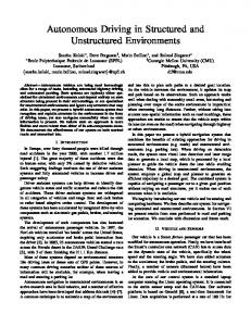
Fig. 2. The Smartter passenger car equipped for autonomous driving. Behind the windscreen we have the camera system, on the sides of the roof we have the tilted laser scanners for corner protection and in the fron the Alasca Scanner.
brake (if in deceleration phase) and steering motor reference. The longitudinal velocity controller is based on a Fuzzy logic controller, which handles also the acceleration/deceleration/cruising phases. The steering column controller is a PID implementation of power steering reference. The underlying vehicle state estimation for vehicle localization is done via Information Filter sensor fusion, available on the vehicle (see [17]). IV. E XPERIMENTS A. Experimental Setup For the validation of the algorithms described in this paper we used SmartTer, our passenger car equipped for autonomous driving. The system is equipped with a localization system based on sensor fusion. Our sensor fusion scheme is based on [18] and [19]. To accurately localize the vehicle, four different sensors are used: DGPS, IMU, optical gyro and vehicle sensors (wheel encoders and steering angle sensor). The combination of their measurements allows the estimation of the vehicle’s 6 degrees of freedom i.e. the 3D position (x, y, z) and the attitude (roll, pitch, heading). The details of the localization system used are described in [17]. For environment detection we use one IBEO Alasca XT laser scanner mounted at the front of the vehicle and two Sick LMS 291 mounted on the roof to protect the vehicle corners as well as a Sony Camera for vision. The system fuses the three different laser scanners in an occupancy grid bound to the moving vehicle coordinate system. This relatively small occupancy grid can easily be transfered to the navigation module described below. Based on that setup we defined a route on the automotive testing ground in Papenburg, Germany that our car followed autonomously. While traversing the predefined waypoints,
Fig. 4. People Detection and Tracking. In the upper part of the figure the laser scan is shown highlighting candidate areas for pedestrians. Those areas are further avaluated in the image. That results in a robust detection ad tracking system for pedestrians. A video illustrating that can be found within the proceedings of the workshop.
people walked into the way of the car to show how the car avoids those obstacles and returns to it’s given path. Those experiments took place over four weeks and ended in a demonstration of the car. B. Results Example results from the pedestrain detection can be seen in figure IV-B. A video of our car navigating the test environment and avoiding pedestrains can be found allong with the article in the workshop proceedings.
Fig. 3.
Snapshots from a video illustrating the avoiding and stopping behavior of our algorithm. The video can be found in the workshop proceedings.
V. C ONLUSIONS We sucessfully evaluated and presented our platform for navigation in cluttered environments, especially under the presence of free moving pedestrians. The vehicle is able to negotiate those obstacles by avoiding them or braking in case no feasable trajectory can be found. The vehicle also showed precise path tracking performance over a time horizon of multiple hours without suffering from effects of drifts in the localization system. Our pedestrian detection system proofed to be robust in various lightning conditions and detected pedestrians of different sizes, distances and speeds. R EFERENCES [1] M. Shell, “Final report of the european esafety working group on road safety, online available,” 2003. [Online]. Available: http://europa.eu.int/informationsociety/activities/esafety/indexen.htm [2] C. Thorpe, T. Jochem, and D. Pomerleau, “The 1997 automated highway demonstration,” in 1997 International Symposium on Robotics Research, 1997. [3] “Darpa grand challenge race website.” [Online]. Available: http://www.darpa.mil/grandchallenge [4] A. Kelly, “An intelligent predictive control approach to the high speed cross country autonomous navigation problem,” Ph.D. dissertation, Carnegie Mellon University, 1995. [5] A. Stentz and M. Hebert, “A complete navigation system for goal acquisition in unknown environments,” Autonomous Robots, vol. 2, no. 2, pp. 127–145, 1995. [6] O. Brock and O. Khatib, “High-speed navigation using the global dynamic window approach,” in IEEE International Conference on Robotics and Automation (ICRA), 1999. [7] S. Singh, R. Simmons, T. Smith, A. Stentz, V. Verma, A. Yahja, and K. Schwehr, “Recent progress in local and global traversability for planetary rovers,” in IEEE International Conference on Robotics and Automation (ICRA), 2000. [8] N. Dalal and B. Triggs, “Histograms of oriented gradients for human detection,” in International Conference on Computer Vision & Pattern Recognition, C. Schmid, S. Soatto, and C. Tomasi, Eds., vol. 2, June 2005, pp. 886–893. [9] Q. Zhang and R. Pless, “Extrinsic calibration of a camera and laser range finder,” in IEEE International Conference on Intelligent Robots and Systems (IROS), 2004, pp. 2301–2306. [10] L. Spinello and R. Siegwart, “Unsupervised detection of artificial objects in outdoor environments,” in 6th International Conference of Field and Service Robotics (FSR07), 2007. [11] “Inria person database,” http://pascal.inrialpes.fr/data/human/. [12] J. Platt, “Probabilistic outputs for support vector machines and comparison to regularized likelihood methods,” B. S. A.J. Smola, P. Bartlett and D. Schuurmans, Eds., 2000, pp. 61–74. [13] D. Ferguson and A. Stentz, “Field D*: An interpolation-based path planner and replanner,” in Proceedings of the International Symposium on Robotics Research (ISRR), 2005. [14] R. Philippsen and R. Siegwart, “An interpolated dynamic navigation function,” in Proceedings of the IEEE International Conference on Robotics and Automation (ICRA), 2005. [15] R. Bartels, J. Beatty, and B. Barsky, An Introduction to Splines for use in Computer Graphics and Geometric Modeling. Los Altos, CA 94022: Morgan Kaufmann Publishers, Inc., 1987.
[16] K. Macek, R. Phillipsen, and R. Siegwart, “Path following for autonomous vehicle navigation with inherent safety and dynamics margin,” in Proceedings of the Intelligent Transportation Systems Conference (ITSC), 2007. [17] P. Lamon, S. Kolski, and R. Siegwart, “The smartter - a vehicle for fully autonomous navigation and mapping in outdoor environments,” In Proceedings of CLAWAR 2006, Brussels, Belgium, 2006. [18] E. N. G. Dissanayake, S. Sukkarieh and H. Durrant-Whyte, “The aiding of a low-cost strapdown inertial measurement unit using vehicle model constraints for land vehicle applications,” in IEEE Transactions on Robotics and Automation, 2001. [19] E. N. S. Sukkarieh and H. Durrant-Whyte, “A high integrity imu/gps navigation loop for autonomous land vehicle applications,” in IEEE Transactions on Robotics and Automation, 1999.