Jan 25, 2018 - D6. D7. D8. P1. Q1. P2. Q2. Q3. Q4. P3. P4. V n inputs can be reduced to n/2 Ps and one V. ATC for partial product reduction (PPR). 6. Proposal ...
A Low-Power High-Speed Accuracy-Controllable Approximate Multiplier Tongxin Yang, Tomoaki Ukezono, Toshinori Sato Fukuoka University, Japan Jan. 25, 2018
Outline
1
Introduction
2
Proposal
3
Experiment
4
Summary
2
Introduction
Approximate multiplier with fixed accuracy
Low power consumption High computing speed
Why accuracy-controllable approximate multiplier? Application quality requirement may vary significantly, The above static approximate multiplier may,
fail to meet application quality requirement waste power when high quality is not required
The objective is to control accuracy according to application requirements at runtime.
3
Proposal
Approximate Tree Compressor
Accurate half adder a b
s
{c,s} = a + b = 2c + s = (c + s) + c; c
Incomplete Adder Cell (iCAC) a b
p
q
p = c + s; q = c;
Sum: {c,s} = p + q
4
Proposal
Approximate Tree Compressor
Structure of multi-bit iCACs A = {an, ..., a1, a0}; B = {bn, ..., b1, b0} b1 a1 b0 a0 bn an
S=P+Q
qn pn
q1 p1
q0 p0
P = {pn, ..., p1, p0}; Q = {qn, ..., q1, q0}
5
Proposal
Approximate Tree Compressor
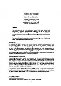
Structure of an ATC with eight inputs (ATC-8) ATC for partial product reduction (PPR) D1 D2 D3 D4
iCACs
D5 D6 D7 D8
iCACs
iCACs
P1 Q1
P2 Q2 Q3
V P3
Q4
iCACs
P4
n inputs can be reduced to n/2 Ps and one V. 6
Proposal
Carry-maskable Adder
Equivalent circuit of a half adder a b
s
a b
s
Cout Cout a half adder
equivalent circuit of a half adder
7
Proposal
Carry-maskable Adder
Carry-maskable half adder (CMHA) mask_x a b
s Cout
mask_x =0(Approximate)
s
= a OR b; Cout = 0;
mask_x =1 (Accurate)
s
= a XOR b; Cout = a AND b; 8
Proposal
Carry-maskable Adder
Carry-maskable full adder (CMFA)
mask_x a b
mask_x a b
CMHA
Cout
Cin
s
Cout
s
Approximate condition: mask_x =0, Cin =0
S = a OR b; Cout = 0; 9
Proposal
Carry-maskable Adder
Carry-maskable adder (CMA) CMA for accuracy controllability a0 b0 m_x0
a1 b1 m_x1
Cin2
Cin1
CMHA
s0
Cout 0
CMFA1
s1
a2 b2 m_x2
Cout 1
Cin7
CMFA2
s2
a7 b7 m_x7
Cout 2
CMFA7 s7
s8
If m_x0, m_x1, ..., and m_x7 are all “0”, carry chain is masked to “0”
10
Proposal
Accuracy-Controllable Multiplier
8-bit Accuracy-Controllable Multiplier Stage1: ATC for PPR 1 1 1 1 1 4 3 2 1 0 9 8 7 6 5 4 3 2 1 0 ATC-8 V1
P1 P1 P2 P3 P4
P2
P3
ATC-4 V2
P6
P5 P5 P6
P4
iCACs
Q7
P7
11
Proposal
Accuracy-Controllable Multiplier
8-bit Accuracy-Controllable Multiplier Stage2
P7 Q7 V2 V1
OR gates for PPR OR gates
Stage3
Stage4
HA
Accurate
Full adders
Controllable
HA
Adders for PPR
Truncated
CMA for accuracy
CMA
controllability
12
Experiment
Experimental Setup
All multipliers are eight bits, Experimental setup synthesized using the same condition For power, delay, and area •
Library: NanGate 45nm
•
RTL language: Verilog HDL
•
Simulator: Synopsys VCS
•
Synthesis: Synopsys Design Compiler
•
Power Consumption: Synopsys Power Compiler
•
Test pattern: 65,536
•
Data changing rate: 0.5GHz
For accuracy •
NMED: Normalized Mean Error Distance
•
RMED: Relative Mean Error Distance
•
ER: Error Rate
13
Experiment
CMA Setting unmasked u bits for accurate result masked (7 – u) bits for approximate result Accurate
Controllable
Truncated
CMA 3 bits
u bits (7-u) bits 3 bits
Bits of CPA: 3 + u Bits of OR gates: 3 + (7 - u)
u
Bits of CPA
Bits of OR gates
m_7b
10
3
m_6b
9
4
m_5b
8
5
m_4b
7
6
m_3b
6
7
m_2b
5
8
m_1b
4
9
m_0b
3
10
14
Experiment
Accuracy
Good
Bad
Multipliers m_7b m_6b m_5b m_4b m_3b m_2b m_1b m_0b AMER_10b AMER_8b AMER_6b AMER_4b ACCI_M2
NMED (%) 0.25 0.26 0.29 0.35 0.49 0.71 1.05 1.64 0.20 0.24 0.46 1.20 0.04
MRED (%) 0.85 0.99 1.31 1.93 3.05 4.57 6.50 9.02 0.62 1.16 3.23 7.53 0.62
ER (%) 36.16 43.46 52.07 61.05 69.61 74.93 78.10 80.02 31.59 55.44 71.12 79.54 72.29
15
Experiment
Power Consumption Power results relative to MRED Proposed
AMER
ACCI_M2
Wallace
200 180
Wallace
160
AMER_10b
140
Power (uW)
120 ACCI_M2
AMER_8b AMER_6b
100 80
m_7b m_6b m_5b m_4b
60
AMER_4b
m_2b
m_3b
m_1b
m_0b
40 20 0 0.00%
1.00%
2.00%
3.00%
4.00%
5.00%
MRED
6.00%
7.00%
8.00%
9.00%
10.00%
16
Experiment
Critical Path Delay Delay results relative to MRED Proposed 1.7
AMER
ACCI_M2
Wallace
Wallace
1.6
AMER_10b
1.5 1.4
ACCI_M2
1.3 1.2 1.1
Delay (ns)
AMER_8b
m_5b
1 0.9
AMER_6b
m_7b AMER_4b
m_6b m_4b
0.8
m_3b
0.7
m_2b m_1b
0.6
m_0b
0.5
0.4 0.3 0.2 0.1 0 0.00%
1.00%
2.00%
3.00%
4.00%
5.00%
MRED
6.00%
7.00%
8.00%
9.00%
10.00%
17
Experiment
Design Area 500
Accuracy setting no any effect on area of proposed multiplier 450 400
Area(um2)
350 300 250 200 150 100 50 0
proposed AMER_4b AMER_6b AMER_8b AMER_10b ACCI_M2 Wallace
18
Experiment
Image Processing Average PSNR from eight images 图表标题 60.0
m_7b
Average PSNR
50.0
10b ACCI_M2
m_6b m_5b
8b
45dB
m_4b 40.0
30.0
m_3b m_2b m_1b
6b 4b
m_0b
20.0
10.0
0.0
Proposed multiplier
1
AMER
19
Summary
Objectives
Solutions
Low-power, High-speed multiplier Accuracy-controllable multiplier Approximate Tree Compressor (ATC) Carry-maskable Adder (CMA)
Results
47.3% ~ 56.2% power reduction 29.9% ~ 60.5% delay reduction 19.7 ~ 52.5 PSNR controllability
20
Thank you!