1372
IEEE TRANSACTIONS ON INDUSTRIAL ELECTRONICS, VOL. 52, NO. 5, OCTOBER 2005
Independent Field-Oriented Control of Two Split-Phase Induction Motors From a Single Six-Phase Inverter Krishna Keshaba Mohapatra, Student Member, IEEE, R. S. Kanchan, Student Member, IEEE, M. R. Baiju, Student Member, IEEE, P. N. Tekwani, Student Member, IEEE, and K. Gopakumar, Senior Member, IEEE
Abstract—Split-phase (six-phase) induction motor stator windings consist of two sets of three phase windings, which are spatially phase separated by 30 electrical degrees. Due to mutual cancel1 ( = 1 3 5... ) lation of the air gap flux for all the 6 order harmonic voltages, called zero sequence components, large harmonic currents are generated in the stator phases. Only the 1( = 0 1 2 3 . . . )-order harmonic voltage components 12 contribute toward the air gap flux and electromagnetic torque production in the machine. In this paper, a novel scheme is proposed where two six-phase induction motors are connected in series with proper phase sequence so that the zero sequence component voltages of one machine act as torque and flux producing components for the other. Thus, the two six-phase motors can be independently controlled from a single six-phase inverter. A vector control scheme for the dual motor drive is developed and experimentally verified in this paper. Index Terms—multiphase winding, series-connected multimotor control, vector control.
I. INTRODUCTION
M
ULTIPHASE motor (in which the number of phases is more than three) drives have become relevant for highpower applications because of inherent advantages like redundancy, reliability and low dc-link voltage requirement [1]–[7]. A six-phase (split-phase) motor can be obtained by splitting the individual stator phase belts of a three phase motor into two equal halves with an angular separation of 30 electrical degrees between the two halves (Fig. 1) [5]. Pulsewidth modulation (PWM) voltages, generated from a six-phase voltage source inverter for driving a six-phase motor, produce three sets of harmonic components. Out of these three sets, only the harmonic ,( )-order components belonging to the develop air gap flux and torque in the machine. The flux be( longing to harmonic components of the order ) cancel each other in the air gap, and, hence, the stator windings carry a large amplitude of current which does Manuscript received August 11, 2004; revised October 6, 2004. Abstract published on the Internet July 15, 2005. K. K. Mohapatra is with the Electrical and Computer Science Department, University of Minnesota, Minneapolis, MN 55455 USA (e-mail:
[email protected]). R. S. Kanchan, P. N. Tekwani, and K. Gopakumar are with the Centre for Electronics Design and Technology, Indian Institute of Science, Bangalore 560012, India (e-mail:
[email protected]). M. R. Baiju is with the College of Engineering, Trivandrum 695016, India (e-mail:
[email protected]). Digital Object Identifier 10.1109/TIE.2005.855659
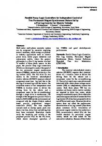
Fig. 1. Six-phase induction motor drive from a six-phase inverter.
not link to the rotor [4]–[6]. The generation of these large harmonic currents in the stator phases is usually limited by the use of large and costly harmonic filters [3]. Another way of eliminating large harmonic currents from the motor stator wind( )-order ings is by removing all of the harmonic components from the phase voltage. This is accomplished by using open-end winding configuration with proper dc-link voltage for the PWM generation [8]. A concept of independent control of series-connected multiphase motors from a single inverter system was suggested for the first time in [9], where a two-motor series-connected fivephase drive was considered. This concept was further advanced and extensively investigated in [10], [11], where vector control technique is applied. Connection schemes were developed for all of the possible odd and even phase numbers in [10] and [11], respectively, and some further investigation for a two-motor sixphase drive system was reported in [12]. Common features of all of the work [9]–[12] conducted so far in this area are the following: 1) only symmetrical multiphase machines (with spatial displacement between any two consecutive phases equal to ) were considered and 2) proof of the possibility of decoupled dynamic control of series-connected machines was always provided by simulation only. This paper provides two main contributions. It considers, for the first time, the possibility of independent control of series-connected asymmetrical multiphase machines (such are the split-phase induction motors). Second, it verifies for the first time experimentally the existence of decoupled dynamics within the series-connected two-motor drive system. In the present work, two six-phase motors of split-phase type are connected in series with proper phase sequence. They are driven from a single six-phase inverter, so that all of the ( )-order harmonic voltages of one motor (zero sequence component) drop across the machine impedance of
0278-0046/$20.00 © 2005 IEEE
MOHAPATRA et al.: INDEPENDENT FOC OF TWO SPLIT-PHASE INDUCTION MOTORS FROM A SINGLE SIX-PHASE INVERTER
the other motor (torque-producing component), and vice versa. ( )-order harmonic curConsequently, the rents for one machine are appropriately controlled by the other machine impedance, and two motors can be independently controlled from a single six-phase inverter drive system, without the need for bulky harmonic filters. Another advantage of the system is that only a single inverter is needed for the dual-motor control. The two motors can also be independently controlled in a single digital signal processing (DSP) platform, this being the same as in the case of series-connected symmetrical multiphase machines. The series connection of the two motors also enables the braking energy of one machine to be used by the other, providing full regenerative capability, as long as the braking energy is less than the total motoring energy [10]. Because of the series connection of two split-phase motors, the stator winding of first motor acts as the harmonic filter for the second motor and vice versa. Hence, harmonic currents of the order ( ) can be eliminated from split-phase motors, without the need for bulky and costly harmonic filters [4]–[7].
II. MODELING OF A SIX-PHASE INDUCTION MACHINE The winding disposition for the split-phase induction motor is shown in Fig. 1. Analysis and control of a six-phase machine, using the concept of vector space decomposition, is available in [4]. The set of harmonic components belonging to the ( ) order, the set of harmonic components be( ) order, and the harlonging to the monic components belonging to the triplen order are separated into three orthogonal subspaces [4]. The six-phase voltages and current harmonics can be analyzed by defining a vector given by denotes (1) [4], shown at the bottom of the page, where the phase separation between the two sets of three phase groups denotes the harmonic order. The harmonics and
1373
( , 2, 4), including the fundamental, of the order ( , 3, span a subspace , the harmonics of the order 5) span a different subspace , and the triplen-order harmonics span the third subspace in the six-dimensional space [4]. All of the possible switching combinations from the six-phase inverter have components in the three subspaces. To decompose the switching combinations into their components in the respective subspaces, a transformation matrix is defined as shown in (2), at the bottom of the page. By using this transformation matrix, all of the harmonic component voltages of the six-phase machine can be decomposed into their respective orthogonal subspaces as shown in (2) [4]. , , and are the phase voltages of the a, b, and c , , and are the phase voltthree-phase group, , are ages of the a', b', and c' three-phase group, the two orthogonal voltage components of the ( )-order harmonic set spanning subspace , , and are the two orthogonal voltage components of the ( )-order harmonic set spanning subspace , and and are the two orthogonal voltages of the [4]. triplen harmonic set spanning subspace By applying the orthogonal transformation to the stator and rotor voltage equations, using transformation matrix , the final transformed stator voltage equations belonging to the vector and can be written as (3a) and (3b), respectively, spaces shown at the bottom of the page [4]. From (3b), it can be indo ferred that the harmonic voltages spanning the subspace not have any mutual flux linkage terms and, hence, they do not contribute to the air gap flux. Hence, all of the harmonic voltages of the order ( ) have to be dropped across the stator resistance and stator leakage inductance, contributing to large harmonic currents (fifth and seventh harmonic currents amplitudes will be more than the fundamental amplitude) in the motor phases [3]–[6].
(1)
(2)
(3a)
(3b)
1374
IEEE TRANSACTIONS ON INDUSTRIAL ELECTRONICS, VOL. 52, NO. 5, OCTOBER 2005
Putting in the new
and ( ) in (4), the orthogonal coordinates subspace are
(5) ( )-order harmonics for Similarly, all of the the winding configuration of Fig. 2 span a subspace defined by Fig. 2. Reconfigured six-phase induction machine.
III. MULTIMOTOR MODE OF THE OPERATION OF TWO SPLIT-PHASE INDUCTION MACHINES As discussed in Section II, because of 30 spatial separation between the two three-phase groups (a, b, c group and a’, ( )-order harmonics b’, c’ group), the fluxes cancel each other in the air gap. In Fig. 2, a six-phase motor stator phase configuration is shown where the spatial phase angle difference between the two sets of the three-phase or (i.e., the a’, b’, c’ phase group winding is ) in space). This will lead the a, b, c phase group by ( new configuration of the six-phase stator winding is achieved by renaming the a, b, c phases of Fig. 1 by a’, b’, c’ and the a’, b’, c’ of Fig. 1 by c, a, b. In this new phase sequence order, the ( )-order harmonic currents produce air ( )-order harmonics gap flux and the do not contribute to the air gap flux production. Similar to that of the normal six-phase motor, as described in the previous section, any harmonic component in any winding can be described , where is the order of the harmonic and by is the spatial phase position of the winding from the reference axis. Hence, the new vector, used for the analysis of six-phase voltage and currents for the winding configuration of Fig. 2, is defined in (4), shown at the bottom of the page. Let us assume that the fundamental vector is rotating in the clockwise direction. Thus, all of the ( )-order harmonics can be grouped into ( ). a subspace by replacing by
(6) Finally, all of the triplen-order harmonics span a subspace defined by (7) In this case also, subspaces each other, i.e.,
,
, and
are orthogonal to (8)
By comparing the new set of subspaces, defined by (5), (6), and (7), with the set of subspaces defined by (2), it is evident defined in (2) is the same as the subspace that subspace defined in (6), and subspace defined by (2) is the same as the subspace defined by (5). Hence, all of the ( )-order harmonics, spanning the sub( space of Fig. 2, behave in the same way as the )-order harmonics spanning the subspace, for the motor configuration of Fig. 1. For the present analysis, the same as in (2) is used for the orthogonal transformation matrix transformation of stator and rotor voltage equations of motor 2, of Fig. 2. The six-dimensional (6-D) voltage equations for the six-phase induction motor of Fig. 2 can also be written in original 6-D space as as (9) where and are the stator voltage and current vectors and is a 6 6 diagonal stator resistance matrix, the same as that of the normal six-phase motor winding configuration (Fig. 1) and are the stator self-inductance [4]. The matrices
(4)
(10)
(11)
MOHAPATRA et al.: INDEPENDENT FOC OF TWO SPLIT-PHASE INDUCTION MOTORS FROM A SINGLE SIX-PHASE INVERTER
matrix and stator-to-rotor mutual inductance matrix, for the new phase-sequence configuration of the six-phase motor of Fig. 2, and of Fig. 1. The and which are different from are as given in (10) and (11), respectively, shown at the , and, in bottom of the previous page, where is equal to (11), is the relative position of rotor with respect to stator.By is from (2)], the applying orthogonal transformation [where following can be obtained,
(12) The final transformed equation will be as follows:
(13)
1375
Similarly, the rotor equation for the phase sequence of Fig. 2 can be written as (14) where the rotor inductance matrix and the rotor-to-stator are as shown by (15) and (16), mutual inductance matrix respectively, as shown at the bottom of the page. By applying orthogonal transformation to (14), the transformed equations repand resenting the orthogonal subspaces can be obtained, as in (17), shown at the bottom of the page, is the rotor leakage inductance and is the mutual where inductance between any two windings with zero angular displacement. Equations (13) and (17) can be written in decoupled form as shown in (18a) and (18b) at the bottom of the page. From the voltage vector equations of (18a), it can be observed that, for the new phase sequence of Fig. 2, the harmonic comhave only diagonal terms in ponents spanning the subspace the mutual inductance matrix. This means that the voltage comsubspace ( , , ponents spanning the order voltage harmonics of the winding sequence of Fig. 1) will not produce any rotating air-gap flux for the winding configuration of Fig. 2. However, the voltage components spanning the ( , -order voltage harmonics for subspace the winding sequence of Fig. 1) will produce a rotating air-gap flux and back emf for the new motor phase sequence of Fig. 2, because of the mutual coupling between rotor and stator, as is evident from (18a) and (18b). Thus, for any switching vector combination of the six-phase inverter, the components in the
(15)
(16)
(17) (18a)
(18b)
1376
IEEE TRANSACTIONS ON INDUSTRIAL ELECTRONICS, VOL. 52, NO. 5, OCTOBER 2005
(a)
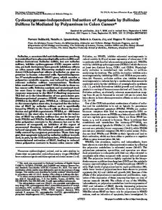
Fig. 4. Generation of control signals for two series-connected split-phase (six-phase) induction motors from one six-phase VSI in vector control mode.
(b) Fig. 3. (a) Schematic of the stator phase windings of the two series connected split-phase (six-phase) induction motors. (b) Terminal connection of the two series-connected split-phase (six-phase) induction motors.
subspace will produce air-gap flux and torque in the machine with the phase sequence of Fig. 2. ( )-order harmonics, All of the subspace (2) have a unique phase relationwhich span the ship among their elements as shown in (19), given at the bottom of the page. corresponds to phase a, Equation (19) signifies that corresponds to phase a’, and corresponds to phase b. (Fig. 1). It can be further noted that the a’, rad from the corb’, c’ phase sequence components lag by responding a, b, c phase sequence components for Fig. 1. This fundamental vector with the phase relationship shown in (19) subspace. This implies that a produces flux and torque in the set of voltages (subspace ) applied to the six-phase machine of Fig. 1, having the phase relation as in (19), irrespective of the frequency of excitation, will produce torque and flux in the motor. Similarly, it can be shown from (5) that the set of voltages (subspace ), which will produce torque and flux in the motor with configuration as in Fig. 2, will have the phase relation given by (20), shown at the bottom of the page, irrespective of the excitation frequency. Equations (3a) and (3b) show that the vectors spanning the subspace produce air-gap flux and torque for subthe configuration of Fig. 1, and the vectors spanning the space will not produce any air-gap flux and torque
in the machine (Fig. 1). Also, from (18a) and (18b), it can be inferred that, for the phase sequence configuration of Fig. 2, the subspace voltage components spanning the will not produce any air-gap flux and torque, whereas the voltage vectors spanning the subspace will produce torque and air-gap flux in the machine. Hence, by connecting in series the six-phase motor with the phase sequence configuration of Fig. 1, with another six-phase motor with the phase sequence configuration of Fig. 2, and driving both from a single six-phase inverter, the two split-phase motors (Fig. 3) can be controlled independently. When the inverter is controlled (PWM) with the combined subreference voltage, the components belonging to the space will predominantly drop across machine-1 to produce air-gap flux and torque, and the components belonging to the subspace will predominantly drop across machine-2 to produce air-gap flux and torque. Hence, no separate harmonic filters are required to suppress the zero sequence components for the two motors can be independently controlled [5]. The scheme explained previously is experimentally verified by operating two split-phase (six-phase) motors of 1- and 2-kW ratings (data given in the Appendix) from a single six-phase VSI, using a vector control scheme (Fig. 4). To prove the principle of the independent vector control of two series-connected split-phase motors, in the present work, the effect of stator voltage drop in one machine due to the flux-/torque-producing component of the current in the other machine is not considered while constructing the reference voltage. To ensure exact control under all operating conditions, these drops have to be compensated, as explained in [12]. In the series-connected multiphase motor drives, windings of each motor carry the combined current and this means that the
(19)
(20)
MOHAPATRA et al.: INDEPENDENT FOC OF TWO SPLIT-PHASE INDUCTION MOTORS FROM A SINGLE SIX-PHASE INVERTER
(a)
(b)
(c)
(d)
0
1377
0
X
Fig. 5. (a) Simultaneous speed reversal of motors [(motor-1 (bottom trace) 500 r/min to 500 r/min and motor-2 (top trace) 300 r/min to 300 r/min -axis 5 s/div. -axis 500 r/min/div]. (b) Torque currents of motor-1 (bottom trace) and motor-2 (top trace) for the condition in Fig. 5(a) [ -axis 2 s/div., -axis 2 A/div.]. (c) Current waveform of phase-a (bottom) and speed (Top Trace) of motor-1, for the condition in Fig. 5(a). (The lower part of the figure shows the time scale expansion of the window part of the top portion of the figure.) [ -axis 2 s/d -axis 2 A/div (current), 500 r/min/div (speed)]. (d) Current waveform of phase-a and speed of motor-2, for the condition shown in Fig. 5(a). (The lower part of the figure shows the time scale expansion of the window part of the top portion of the figure.) [ -axis 2 s/div. -axis 2 A/div (current), 500 r/min/div (speed)].
Y
X
Y
X
Y
stator losses will be increased, compared to a single motor drive system [10], [11]. It should also be noted that, since both the motors are driven by the single inverter system, the inverter rating has to be at least equal to the sum of the power ratings of the individual motors (actually, slightly higher due to the additional stator winding losses in both machines, caused by the flow of the nonflux-/torque-producing current).
X
Y
The control signals are generated using a TMS320F2407based DSP platform. Fig. 4 shows that there are two separate control loops for motor-1 and motor-2. The outer speed loop gives the torque current command and the inner current control loops for torque current control and flux current control generate the voltage command in the synchronous reference frame. ) as in By applying inverse transformation (
IV. EXPERIMENTAL RESULTS AND DISCUSSION The proposed scheme is implemented for independent vector control of two series-connected split-phase (six-phase) induction motors of power ratings 2 kW (2-pole, machine-1) and 1 kW (4-pole, machine-2) (Fig. 3). The control block diagram used for the vector control operation is shown in Fig. 4. A sixphase IGBT-based inverter is used to drive the series-connected motors. The schematics of the stator phase windings of the two series connected motors are shown in Fig. 3(a) and (b).
(21) (22) the reference voltages and currents for the six inverter phases, for the PWM control, can be obtained. The reference voltage vector from (21) is used for the PWM generation of the inverters [6]. The feedback currents for the current control
1378
IEEE TRANSACTIONS ON INDUSTRIAL ELECTRONICS, VOL. 52, NO. 5, OCTOBER 2005
(a)
(b)
(c)
(d)
0
0
Fig. 6. (a) Speed reversal of motor-1 (bottom trace) and motor-2 at different instants (motor-1: 500 r/min to 500 r/min and motor-2 between 300 r/min to 300 r/min). [ -axis 5 s/div. -axis 500 r/min/div (speed)]. (b) Torque currents of motor-1 (bottom trace) and motor-2 (top trace) for the condition shown in Fig. 6(a) ( -axis 2 s/div. -axis 2 A/div). (c) Current waveform of phase-a and speed of motor-1 for the condition shown in Fig. 6(a). (The lower part of the figure shows the time scale expansion of the window part of the top portion of the figure.) [ -axis 2 s/div. -axis 2 A/div (current), 500 r/min/div (speed)]. (d) Current waveform of phase-a and speed of motor-2 for the condition shown in Fig. 6(a). (The lower part of the figure shows the time scale expansion of the window part of the top portion of the figure.) [ -axis 2 s/div. -axis 2 A/div (current), 250 r/min/div (speed)].
X
X
Y
Y
X
Y
X
loop are obtained from the subspace component , for the control loop of machine-1 and subspace components , for the control loop of machine-2 (22). To operate the motor in the overmodulation region, a modulation scheme is implemented where the PWM output can go smoothly to six-step mode [13]. To test the independent speed control property, machine-1 is allowed to make a speed reversal between 500 r/min to 500 r/min, and machine-2 is allowed to make speed reversal between 300 r/min to 300 r/min simultaneously. The corresponding speed response signals are shown in Fig. 5(a). Fig. 5(b) shows the torque currents of both the machines during the simultaneous speed reversal. A slight dip in the torque current of motor-1 is visible in Fig. 5(b) and this will be improved if we do the exact voltage compensation of the stator voltage drop due to the current of motor – 2, as suggested by Jones et al., in [12].
Y
Fig. 5(c) and (d) shows the combined currents in phase-a and the speed of motor-1 and motor-2, respectively. Next, the machines are subjected to speed reversal at different instants, as shown Fig. 6(a). The corresponding torque currents are shown in Fig. 6(b). The feedback currents for the control of machine-1 are subspace and the feedobtained from the components in the back currents for the control of machine-2 are obtained from (22). From Fig. 6(a) and the components from the subspace (b), it can be observed that when one motor is making speed reversal, the speed of other motor is unaffected. In Fig. 6(c) and (d) the phase current and speed of a machine are shown when only one motor is making speed reversal and the other machine is running at constant speed. The phase current shows that there are two fundamental frequency components, where each frequency component corresponds to the excitation frequency of individual machines. It can be noted in Fig. 6(c) and (d) [when compared to Fig. 5(c) and (d)], during zero crossing of the speed
MOHAPATRA et al.: INDEPENDENT FOC OF TWO SPLIT-PHASE INDUCTION MOTORS FROM A SINGLE SIX-PHASE INVERTER
(a)
(b)
(c)
(d)
1379
X X
0
Fig. 7. (a) Current waveform of phase-a and speed of motor-1 (motor-1 is making speed reversal from 300 r/min to 300 r/min and motor-2 is stationary) [ -axis 2 s/div. - axis 1 A/div (current), 250 r/min/div (speed)]. (b) Current waveform of phase-a and speed of motor-2, for the condition shown in Fig. 7(a) [ -axis 2 s/div. -axis 1 A/div (current), 250 r/min/div (speed)]. (c) Current waveform of phase-a and speed of motor-1 (motor-1 is accelerating at constant rate from 400 to 500 r/min and motor-2 is stationary). -axis 2 s/div, -axis 1 A/div (current), 50 r/min/div (speed). (d) Current waveform of phase-a and speed of motor-2 (motor-1 is accelerating at constant rate from 400 to 500 r/min and motor-2 is stationary) [ -axis 2 s/div. -axis 1 A/div (current), 50 r/min/div (speed)].
Y Y
X
Y
reversal, that one frequency component is of fixed frequency and the other frequency component varies, as the speed of the corresponding machine changes. In Fig. 7(a) and (b), the speed and phase current are shown when one motor is at standstill and other motor makes speed reversal. While motor-2 is at standstill (Fig. 7(b)) the other motor (motor-1) is performing the speed reversal [Fig. 7(a)]. Next, motor-1 is accelerated while motor-2 is held stationary and the phase current is observed during the acceleration. From Fig. 7(c), it can be observed that the amplitude of phase current increases during the acceleration period, due to the enhanced torque current component and settles down to the original value once the speed stabilizes. Fig. 7(d) shows that the speed of the motor-2 is unaffected while motor-1 is accelerated. These experiments demonstrate that, with the proposed scheme, two series-connected split-phase motors can be controlled independently.
X
Y
The steady-state waveforms of the proposed drive scheme are presented in Figs. 8 and 9. Fig. 8 refers to the condition where the motors are running in opposite direction at different speed. Fig. 8(a) shows the -component reference phase voltages from the controller, for motor-1 and motor-2. The two reference voltages are at different frequencies, because the motors are running at two different speeds (motor-1 running at 500 r/min and motor-2 running at 300 r/min in opposite direction). The combined reference voltage for this mode of operation for the phases (a-phase and a’-phase) is shown in Fig. 8(b).The reference phase voltages shown Fig. 8(b) indicate that there is a superposition of two frequency components. The corresponding actual machine voltages are shown in Fig. 8(c) and the corresponding currents are shown in Fig. 8(d). The motor is operated next in the overmodulation region by following the algorithm proposed in [13]. In this case, only one motor is allowed to operate in overmodulation and the
1380
IEEE TRANSACTIONS ON INDUSTRIAL ELECTRONICS, VOL. 52, NO. 5, OCTOBER 2005
(a)
(b)
(c)
(d)
Fig. 8 (a) Reference voltage of alpha phase of motor-1 (bottom trace) and motor-2 (top trace) (motor-1 at 500 r/min and motor-2 at 300 r/min; motors are running in opposite direction) [ -axis 100 ms/div. -axis 100 mv/div.]. (b) Combined reference voltage of a-phase (top trace) and a’-phase (bottom trace) of motor-1and motor-2, for the condition shown in Fig. 8(a) ( -axis 100 ms/div, -axis 100 mv/div). (c) Combined voltage waveform of phase-a and phase-a’ of motor-1 (bottom trace) and motor-2 (top trace) for the condition in Fig. 8(a) [ -axis 20 ms/div. -axis 50 V/div]. (d) Phase current of a-phase (top trace) and a’-phase (bottom trace) of motor-1 and motor-2, for the condition in Fig. 8(a) [ -axis 100 ms/div. -axis 2 A/div].
X
Y
X
Y X X
other is at standstill. Fig. 9(a) and (b) shows the phase current and phase voltages for this overmodulation case. The current waveform, shown in Fig. 9(a), indicates the presence of fifthand seventh-order harmonics. From Fig. 9(b), it can be noted that the fifth- and seventh-order harmonic voltages drop across the phases of the standstill motor. The fifth- and seventh-order harmonic currents are limited in amplitude [Fig. 9(a)] because of the impedance offered by the standstill motor. This shows that the proposed scheme, while achieving independent control of two series-connected split-phase motors, additionally eliminates the need for the fifth- and seventh-order harmonic filters.
V. CONCLUSION A detailed theoretical analysis with experimental verification, for the independent FOC of two series-connected split-phase
Y Y
(six-phase) induction motors supplied from a single six-phase inverter system, is presented. This scheme is introduced in this paper for the first time, and the experimental verification of independent vector control, within a series-connected multiphase drive system is also provided, for the first time. The two split-phase (six-phase) motors are controlled independently, without the need for bulky and costly harmonic filters, for limiting the fifth- and seventh-order harmonic currents. Also, the independent control of two series-connected motors is achieved using a single DSP platform. Because of the series connection of the motors, bulky and costly harmonic filters ( )-order are not needed to suppress the harmonic currents in the stator phases. Due to the series connection, each machine will carry the combined currents and, hence, the fundamental stator loss is increased, compared to two independent single motor drives, while low-order harmonic stator winding loss is reduced.
MOHAPATRA et al.: INDEPENDENT FOC OF TWO SPLIT-PHASE INDUCTION MOTORS FROM A SINGLE SIX-PHASE INVERTER
[4] Y. Zhao and T. A. Lipo, “Space vector PWM control of dual three-phase induction machine using space vector decomposition,” IEEE. Trans. Ind. Appl., vol. 31, no. 5, pp. 1100–1109, Sep./Oct. 1995. [5] K. Gopakumar, V. T. Ranganathan, and S. R. Bhat, “Split-phase induction motor operation from PWM voltage source inverter,” IEEE Trans. Ind. Appl., vol. 29, no. 5, pp. 927–933, Sep./Oct. 1993. [6] , “An efficient PWM technique for split-phase induction motor operation using dual voltage source inverters,” in Conf. Rec. IEEE-IAS Annu. Meeting, Toronto, ON, Canada, Oct. 1993, pp. 586–588. [7] , “Vector control of induction motor with split-phase windings,” EPE J., vol. 7, no. 1–2, pp. 61–66, Aug.-Oct. 1997. [8] K. K. Mohapatra, K. Gopakumar, V. T. Somasekhar, and L. Umanand, “A harmonic elimination scheme for an open-end winding induction motor drive,” IEEE Trans. Ind. Electron., vol. 50, no. 6, pp. 1187–1198, Dec. 2003. [9] S. Gataric, “A polyphase Cartesian vector approach to control of polyphase AC machines,” in Proc. IEEE IAS Annual Meeting, Rome, Italy, 2000, CD-ROM. [10] E. Levi, M. Jones, S. N. Vukosavic, and H. A. Toliyat, “A novel concept of a multiphase, multimotor vector controlled drive system supplied from a single voltage source inverter,” IEEE Trans. Power Electron., vol. 19, no. 3, pp. 320–335, Mar. 2004. [11] E. Levi, M. Jones, and S. N. Vukosavic, “Even phase multi-motor vector controlled drive with single inverter supply and series connection of stator windings,” Proc. IEE—Electr. Power Appl., vol. 150, no. 5, pp. 580–590, Sep. 2003. [12] M. Jones, S. N. Vukosavic, and E. Levi. Independent vector control of a six-phase series connected two motor drive. presented at Proc. IEE PEMD Conf. [13] J.-O. Krah and J. Holtz, “High performance current regulation and efficient PWM implementation for low impedance servo motors,” IEEE. Trans. Ind. Appl., vol. 35, no. 5, pp. 1039–1045, Sep./Oct. 1999.
(a)
(b) Fig. 9. (a) Current waveform of phase-a (Motor-1 is stalled and motor-2 is running at six step mode). [ -axis 20 ms/div. -axis 1 A/div]. (b) Voltage waveform of phase-a’ of motor-1 (bottom trace) and motor-2 (top trace). (Motor-1 is stalled and motor-2 is running at six step mode). The middle trace is the combined voltage. [ -axis 10 ms/div. -axis 20 v/div].
X
Y
X
1381
Y
Krishna K. Mohapatra (S’01) received the B.E. degree from R.E.C. Rourkela, India, in 1993 and the M.Tech degree from the Indian Institute of Technology, Kharagpur, in 1996, both in electrical engineering, and the Ph.D degree from the Centre for Electronics design and Technology, Indian Institute of Science, Bangalore, India, in 2003. He was a Design and Development Engineer with National Radio and Electronics Company, Ltd., from 1995 to 2000. His research interests are in the area of power converters, pulsewidth modulation strategies, and motor drives. He is currently pursuing a postdoctoral fellowship at the University of Minnesota, Minneapolis.
APPENDIX
, H,
R. S. Kanchan (S’02) received the B.E. degree in electrical engineering from the Walchand College of Engineering, Sangli, India, in 1998 and the M.Tech. degree in electrical engineering from the Indian Institute of Technology, Bombay, India, in 2000. He is currently working toward the Ph.D. degree at the Centre for Electronic Design and Technology (CEDT), Indian Institute of Science, Bangalore, India. He was with Tata Steel Company, Jamshedpur, India, from 2000 to 2002.
[1] T. M. Jahns, “Improved reliability in solid state AC drives by means of multiple independent phase–drive units,” IEEE Trans. Ind. Appl., vol. IA-16, no. 3, pp. 321–331, May/Jun. 1980. [2] E. Andresen and K. Bieniek, “6-phase induction motors for current source inverter drives,” in Conf. Rec. IEEE-IAS Annu. Meeting, Philadelphia, PA, Oct. 1981, pp. 607–612. [3] E. A. Klingshirn, “Harmonic filters for six-phase and other multi phase motors on voltage source inverter,” IEEE Trans. Ind. Appl., vol. 1A-21, no. 4, pp. 588–593, May/Jun. 1985.
M. R. Baiju (S’01) received the B.Tech degree in electronics and communication engineering from the College of Engineering, Trivandrum, India, in 1988, and the M.Tech. and Ph.D. degrees from Centre for Electronic Design and Technology, Indian Institute of Science, Bangalore, India, in 1997 and 2004, respectively. From 1988 to 1991, he was with the National Thermal Power Corporation Ltd., New Delhi, and since 1991 he has been a faculty at College of Engineering, Trivandrum.
The data of the two split-phase motors used for the present work (based on the equivalent circuit model presented in [7]) are given as follows. , , Motor 1: 2 kW, 2 pole. H, H, , ,
Motor 2: 1 kW, 4 pole. H, H,
H
REFERENCES
1382
IEEE TRANSACTIONS ON INDUSTRIAL ELECTRONICS, VOL. 52, NO. 5, OCTOBER 2005
P. N. Tekwani (S’04) received the B.E. degree in power electronics from the Lakhdhirji Engineering College, Morbi, India, in 1995 and the M.E. degree in electrical engineering from the Maharaja Sayajirao University, Vadodara, India, in 2000. He is currently working toward the Ph.D. degree at the Centre for Electronic Design and Technology, Indian Institute of Science, Bangalore, India. From 1996 to 2001, he was with the Electrical Research and Development Association (ERDA), Vadodara, India, and since 2001 he has been a Member of the Faculty with the Nirma Institute of Technology, Ahmedabad, India.
K. Gopakumar (SM’96) received the B.E., M.Sc.(Engg.) and Ph.D. degrees from the Indian Institute of Science, Bangalore, India, in 1980, 1984, and 1994, respectively. He was with the Indian Space Research Organization from 1984 to 1987. He is currently an Associate Professor with the Centre for Electronics Design and Technology, Indian Institute of Science, Bangalore, India. His fields of interest are power converters, pulsewidth modulation techniques, and ac drives.