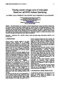
Input current shaper based on the series connection of a voltage ...
Recommend Documents
Dec 10, 2014 - If a high voltage source is available but load requirement ... 2013; Nami et al. 2011; Wang ... A general block diagram of series-modular DC-DC.
exceeds the PT power handling limit, the use of a multiple connected PT is needed [1-4]. For the multiple configurations of PTs, the thermal balance is important ...
by the series connection of three IGBT's with conventional snubber circuits. The experimental results show the voltage balancing by an active control with wide ...
a number of power converters with a lower power rating are employed to bring ..... is required for parallel operation of the power supplies in a redundant system.
The core of the proposed circuit is translinear ohm's law principle, which is implemented by a floating-voltage source and a pseudo-linear resistive element.
solar panel have been drawn quickly using the MOSFET as an electronic load, which is controlled by means ... calculation, the so called one diode model that is.
Timothy N. Chang and Edwin Hou. Elec. & Comp. .... tion computed at a speci ed time tv. The frequency .... comparison. For smaller damping coe cients ( < 0:13).
parallel (ISOP), load sharing, modular converter, voltage sharing. I. INTRODUCTION. AFULLY ...... (a) Converter input voltages (400 mV/div, 5 A/div, and 10 ms/div). .... [Online]. Available: http://www.synqor.com/pdf/appnt_System_Instability.pdf.
Politehnica University of Timisoara, Department of Automation and Industrial ... Keywords: Observers, Estimation techniques, Flux control, PM motor drives, Robust ..... Drives. Applications to PMSM (book in Romanian). Orizonturi Universitare ...
The DCFDCCIIÑ architecture used is based on the design given in Ref. 6. The .... diagram are shown in Figs. 6 and 7 .... Three-bit CDN CMOS circuit diagram.
71, n, pp. 817-819 1991. [7] Sedar and K.C. Smith, âA second Generation current conveyor and its applications,â IEEE transactions circuit theory, vol. CT-17, pp.
Apr 10, 2014 - With Rail-To-Rail Output Range for the HYDE. Detector at FAIR. J. Galán, R. López-Ahumada, T. Sánchez-RodrÃguez, A. Torralba, Senior ...
SAE JIQJQ. ENGINE DATALINK. SERVICE CONNECTOR. FUEL UFT PUMP RELAY POWER. WATER-INâF'UEL. FUEL 8: TIMING ACTUATORS,. C
Nov 6, 2014 - system and the coal-based methanol production system are integrated. ... fuel exergy [1], limits the improvement of their thermal efficiency.
MAXIM OPERATHC SPEED/GOVERNOR TYPE SWITCH. REMOTE ACCELERATOR ON/OFF SWITCH maroon/mm. ACCELERATOR ERRCIT LIMP HCHE SWIT
May 16, 2011 ... Keyence KV/KZ Series .....................................................................................73. Koyo...
.............................................................................. 75.
Abstractâ Logic-level estimators of leakage currents, in nanoscale standard-cell-based designs, are relevant for the dra- matic speed advantage with respect to ...
In this manual, the following items are generically called "motor". - Servo motor. -
Spindle motor ... Earth ground the controller, drive unit and motor according to the
local laws. (In Japan, ground the 200V ..... 1.2 General Connection Diagram .
rents, which are not multiple integer of the fundamental supply. H. Soltani, P. ..... instrument does not preclude the application of other analysis principles like ..... [26] Electromagnetic compatibility (EMC) â Part 4-7: Testing and Mea- suremen
Effects of Passive Components on the Input Current. Interharmonics of Adjustable-Speed Drives. Hamid Soltani, Student Member, IEEE, Frede Blaabjerg, Fellow ...
Instruction on Learning Grammar by ... Iranian Intermediate EFL learners. ... grammar. The Journal of English Language Pedagogy and Practice. Vol.11, No.22, ...
... Hyun Woo Seoa, Young-Ku Jina,Ki-Seong Leea, Minku Leeb, and Dong Min ...... L. Han, Measuring methods of cell performance of dye-sensitized solar cells, ...
The evaluation presented takes into account ... ASD manufacturers have developed multiple types of drives to answer the ... limited, as shown in Table I. These drives can be classified into two ..... topology to drive 6.6 kV motors at high-power leve
Input current shaper based on the series connection of a voltage ...
IEEE TRANSACTIONS ON INDUSTRY APPLICATIONS, VOL. 37, NO. 2, MARCH/APRIL 2001
583
Input Current Shaper Based on the Series Connection of a Voltage Source and a Loss-Free Resistor Javier Sebastián, Member, IEEE, Marta María Hernando, Member, IEEE, Arturo Fernández, Member, IEEE, Pedro José Villegas, Member, IEEE, and Juan Díaz
Abstract—A new input current shaper is proposed in this paper. The operating principle is based on the connection of a voltage source and a loss-free resistor (LFR) between the input rectifier and the bulk capacitor in a conventional switching-mode power supply with no power-factor correction. Both the voltage source and the LFR are obtained as an additional output from the converter’s transformer. This additional output is a forward-type one with one extra inductor. With the final topology, a good tradeoff between capacitor voltage, recycling energy, and harmonic content can be established in order to comply with IEC 1000-3-2 specifications. Index Terms—IEC 1000-3-2 specifications, power-factor correction, power supplies.
I. INTRODUCTION
I
N SEARCH OF low-cost high-performance ac-to-dc power converters complying with IEC 1000-3-2 specifications, many power topologies have been proposed and investigated. These topologies can be divided into passive and active solutions. On the one hand, the major reason for the interest in employing passive solutions in the waveshaping of the line current arises from its simplicity, which implies their potential to meet the desired specifications with high efficiency and low cost [1]. The input current waveform obtained with passive solutions is not sinusoidal since very bulky inductor should be used to obtain a perfect sinusoidal input current [2]. Therefore, the main objective is to meet IEC 1000-3-2 specifications instead of obtaining an almost perfect input current with very high power factor (PF). On the other hand, active solutions with fast output voltage regulation are usually based on two switching conversion stages (input current waveshaping plus dc-to-dc conversion) [3], [4], sometimes integrated in one stage which processes twice the output power [5], [6], sometimes with two stages which process the output power less than twice [7]–[10]. In all these cases, the input current is sinusoidal [or quasisinusoidal when using Paper IPCSD 00–055, presented at the 1998 IEEE Applied Power Electronics Conference and Exposition, Anaheim, CA, February 15–19, and approved for publication in the IEEE TRANSACTIONS ON INDUSTRY APPLICATIONS by the Industrial Power Converter Committee of the IEEE Industry Applications Society. Manuscript submitted for review July 28, 1998 and released for publication December 19, 2000. The authors are with the Departamento de Ingeniería Eléctrica, Electrónica, de Computadores y Sistemas, Universidad de Oviedo, 33204 Gijón, Spain (e-mail: [email protected]; [email protected]; [email protected]; [email protected]; [email protected]). Publisher Item Identifier S 0093-9994(01)02494-X.
Fig. 1.
(a) Proposed solution. (b) Equivalent circuit.
stages based on a boost converter operating in discontinuous conduction mode (DCM)]. However, a third option has recently been proposed. This option is based on using standard dc-to-dc topologies with slight changes in order to comply with regulations (such as IEC 1000-3-2) at as low a cost as possible [11]–[15]. In this case, the main objective, as in the case of using passive solutions, is not to obtain a sinusoidal (or almost sinusoidal) input current, but to obtain an input current with a harmonic content which meets the regulations. Cost and efficiency are of primary concern here. In this paper, a new solution to meet standards IEC 1000-3-2 with only a slight modification of well-known topologies (flyback, forward, half-bridge, Sepic, Cuk, etc.) is proposed. This solution is based on the connection of one additional output of the converter [obtained from the converter’s transformer; see Fig. 1(a)] between the input rectifier and the low-frequency filter ). In appearance, the additional capacitor (bulk capacitor output is similar to the main output of a forward converter. has been connected in series However, an extra inductor . Thus, this output with the high-frequency rectifier diode is a “delayed output,” proposed in [16] as the second output in a type of new completely regulated two-output dc-to-dc converter. With this extra inductor and with the output inductor
IEEE TRANSACTIONS ON INDUSTRY APPLICATIONS, VOL. 37, NO. 2, MARCH/APRIL 2001
Forward converter with an additional inductor.
working in continuous conduction mode (CCM), the Thévenin equivalent of the additional output consists of a voltage source plus a loss-free resistor (LFR) [see Fig. 1(b)]. By properly choosing both elements (voltage source and LFR), a good tradeoff between efficiency and harmonic content can be estabhelps the low-frequency diodes lished. The voltage source of the input rectifier to start conducting. In fact, they start conreaches the ducting when the input voltage , being the voltage across the bulk capacitor value . Thus, the input current waveform will be if if
Fig. 3.
Main waveforms in the converter shown in Fig. 2.
(1)
Therefore, the input current waveform consists of pieces of positive and negative sinusoids [see Fig. 1(b)], whose conduccan be chosen to meet regulations with as low a tion angle recycling power as possible. II. IMPLEMENTATION OF THE VOLTAGE SOURCE AND THE LFR The implementation of the voltage source plus the LFR is based on the converter shown in Fig. 2. It is a forward converter in series with the rectifier diode with an additional inductor . Due to this inductor, the freewheeling diode stops conducting later than in a forward converter without the additional [16], as can easily be deduced from Fig. 3. Thus, inductor this inductor is called a “delaying inductor” and the converter a “delayed forward converter.” The delay time can be easily computed as (2) The effective duty cycle
at the input of the output filter will
be
Fig. 4. Normalized output characteristic (v =(nV ) )) for different values of L.
L f =(nV
versus i
1
an LFR . It should be noted that no energy is dissipated in the converter (and, therefore, in the equivalent LFR) if all the components are ideal. It should also be noted that the is transferred to the demagnetizing voltage energy stored in source ( in this case) through the demagnetizing winding. Finally, Fig. 4 shows the normalized output characteristic (without output voltage feedback loop) of this converter . As this (Fig. 2), for different values of the quotient figure shows, values of this quotient larger than 5 or 10 ensure that the output characteristic is almost ideal.
(3) III. IMPLEMENTATION OF THE PROPOSED SHAPER where is the switching frequency. Therefore, neglecting the current ripple through inductor (that is, and, therefore, ), the output voltage will be (4) This equation can be rewritten as follows: (5) Therefore, the output voltage has an open-control-loop equivand alent circuit that consists of a voltage source
Fig. 5(a) shows a first implementation of the proposed converter, in this case based on a flyback converter. Two modifications of this topology are shown in Fig. 5(b) and (c), where the transformer has been finally substituted for an autotransformer [Fig. 5(c)]. One additional tap in the transformer, two ) and two diodes ( and ) are the only inductors ( and differences between this topology and a conventional flyback converter. All this new elements constitute an “active input-current shaper” (AICS) (see Fig. 6). The implementations shown in Fig. 6(a) and (c) seem to be very similar to the one proposed
SEBASTIÁN et al.: INPUT CURRENT SHAPER
585
(a)
(a)
(b)
(b)
(c) Fig. 5. Implementation of the proposed converter based on a flyback. (a) Implementation directly obtained from Fig. 1(a). (b) After moving , , and . (c) Using an extra tap instead of an additional winding.
D
LL
(c) Fig. 6. AICS concept. (a) Using a transformer with an extra tap and (b) With no extra tap. (c) Using a transformer with an extra tap and
in [11]. However, two important differences must be taken into account. 1) There is an extra inductor ( ). 2) The input inductor is operating in CCM instead of in DCM. It should be noted that operation in CCM decreases current stress in the power transistor. A topology that is particularly easy to implement is shown in Fig. 6(b), where a degree of freedom has been lost because there is no additional tap in the transformer. In this case, the topology seems to be very similar to the one proposed in [6]. However, the above mentioned differences also exist here. Implementations based on other topologies with a transformer (forward, Sepic, Cuk, zeta, push-pull, half-bridge and full-bridge) are also possible. Fig. 7 shows two of them, both based on the forward converter.
IV. ANALYSIS OF THE PROPOSED INPUT CURRENT SHAPER BASED ON FLYBACK’S FAMILY DC-TO-DC CONVERTERS As has been mentioned, the input current in a half cycle of can the input voltage is given by (1). The conduction angle
n n
. .
be easily obtained from (1) (6) Therefore, the conduction angle is a function of the voltages , , and [see Fig. 1(b)]. The peak value of the input voltage , , is an independent variable which varies from to . The value of the equivalent voltage source will be [see Fig. 6(a)] (7) depends on , on the duty cycle , and on Therefore, of the additional tap of the transformer. the ratio of turns allows us to consider as a deThis last parameter propsign variable, because it can freely be set by setting erly. across the bulk capacitor depends on the The voltage and design conditions, on the peak value of input voltage
586
IEEE TRANSACTIONS ON INDUSTRY APPLICATIONS, VOL. 37, NO. 2, MARCH/APRIL 2001
(a)
(a)
(b)
(b) Fig. 7. Implementation based on forward-type converters. (a) With conventional demagnetizing system. (b) Using active clamp.
on the converter load. Voltages and are related by the must be maintained fact that the converter output voltage constant by the output voltage feedback loop. Thus, taking into account that the converter is a flyback (or a member of the flyback’s family of dc-to-dc converters, that is, Sepic, Cuk, or zeta) in CCM, the following equation can be written:
(c) Fig. 8. First design example. (a) Normalized input current as a function of the conduction angle (#1: V and P ; #2: V and P ; #3: V and P =2; #4: V and P =2). (b) Normalized voltage across C and (c) conduction angle versus normalized output power.
(8) and the amount of In order to mininize the voltage across recycled energy, the value of the LFR must be set in such a way and that the voltage drop across the series connection of when the input current is maximum (peak value of , minimum and maximum input power, ), is 0. In these value of will be at its minimum value , whereas conditions, will be at its maximum value . Therefore,
(14) The average input power at the line will be (15) This equation becomes
(9) and, from (7), (6), and (8), (16) (10) can be obtained from (16) at maximum The value of and minimum input voltage power (11) (12) and can be written as functions of the The voltages and duty cycle and of the design parameters (13)
(17) , From (6), (13), (14), (16), and (17), the evolution of and as functions of the design parameters ( , either or and ) and the operating point ( and ) can be obtained by using Mathcad 5.0. One example of design is shown in Fig. 8.
SEBASTIÁN et al.: INPUT CURRENT SHAPER
587
(a)
(b)
Fig. 9. (a) PF and (b) THD as a function of the conduction angle and (c) THD as a function of the normalized input power for a specific design ( = 120 ).
Thus, in this case, , and the . The input current maximum value of is and will be a perfect sinusoid [Fig. 8(a)]. The at normalized input current for different input voltages and output powers are also shown in Fig. 8(a). The variation of the voltage in this case is given in Fig. 8(b), whereas the conduction is shown in Fig. 8(c). This design leads to high PF and angle low total harmonic distortion (THD), as it corresponds to high (see Fig. 9). However, the values of the conduction angle main disadvantage of such a design is that the capacitor voltage undergoes a significant change when the normalized power changes. Lower capacitor voltage change (although lower PF and . higher THD) can be obtained by choosing Fig. 10(a) is similar to Fig. 8(a), but with and , whereas Fig. 10(b) and (c) shows and in this case.
(c) Fig. 10. Second design example. (a) Normalized input current as a function of the conduction angle . (b) Normalized voltage across C and (c) conduction angle versus normalized output power.
input current waveform is going to be assumed to always be in CCM, as is shown in Fig. 11(b), which means a worst case analysis from the point of view of harmonic content. The proposed converter may operate either in Class A or . As Fig. 11(b) Class D, depending on the conduction angle shows, the input current waveshape belongs to Class D when , which is a more restrictive class than Class A. Therefore, the following study will focus on the conditions to meet IEC 1000-3-2 when the converter is operating in such a way that the input current waveshape belongs to Class D. From (15), it can easily be obtained that
V. MEETING IEC 1000-3-2 SPECIFICATIONS The actual input current waveform obtained with any of the proposed topologies based on the use of an AICS is depicted in Fig. 11(a). As this figure shows, the inductor is operating in the DCM when the input current is very low. In fact, the input current corresponding to start operating in the DCM depends and on the design conditions (at full load on the quotient , the operation in and for a specific design, when DCM starts when the input current is 10 lower than the peak value). The harmonic content obtained taking into account the operation in DCM is lower than the harmonic content when the inductor is always operating in CCM. Due to this fact, the
(18)
where
(19) and (20)
588
IEEE TRANSACTIONS ON INDUSTRY APPLICATIONS, VOL. 37, NO. 2, MARCH/APRIL 2001
(a)
(b)
Fig. 12. Minimum conduction angles that comply with IEC 1000-3-2 specifications. (a) Harmonics 3rd–7th. (b) Harmonics 9th–13th. Fig. 11. (a) Actual input current waveform and (b) boundary between Class A and Class D.
From (19) and (20), the rms value of each input current harcan be computed by Fourier analysis as follows: monic (21) Dividing (21) by (18), we obtain the relative value of each as appears in the regulation for Class D harmonic (22) These values must be lower than the ones specified by the . Therefore, the regulation in Class D for each harmonic , condition to comply with the regulation will be LIMD
(23)
Fig. 12 shows (23) for the first harmonics at 220 V. As this figure shows, the more restrictive case corresponds to the third harmonic, which determines the minimum conduction angle that allows regulation compliance. This conduction angle is 1.177 rad (that is, 67.44 ) at 220 V. At 230 V, the most restrictive harmonic is the eleventh, which determines a minimum conduction angle of 64.47 . It should be noted that, due to the fact that the converter must comply with the regulations only at maximum power (according to the IEC 1000-3-2 specifications), the compliance is guaranat full load is higher than 67.44 teed if the conduction angle at 220 V and 64.47 at 230 V. VI. DESIGN PROCEDURE The design procedure of an AICS for the flyback and for the flyback-type family (Sepic, Cuk, and zeta) converters is given in this section. The inputs of this design are the output voltage , the maximum input power , and the maximum and and . The minimum values of the input voltage steps can be summarized as follows.
Step 1) Choose (the value of the conduction angle at the input voltage specified in the regulations), according to a tradeoff between harmonics reduction and recycled energy. In any case, this conduction angle must be higher than 67.44 at 220 V and 64.47 at 230 V. (the maximum value of the conStep 2) Calculate ), by solving the following equaduction angle tion, obtained from (16):
(24) (the minimum value of ), acStep 3) Calculate cording to the following equation, obtained from (11): (25) Step 4) Choose either the maximum value of the duty cycle, , or the ratio of turns of the additional tap of the transformer. Both quantities are related by (10) and, therefore, one of them can be obtained from this equation if the other is known. The value of can be easily obtained form the ratio of turns (12). from (17). The value of the delaying Step 5) Calculate inductor will be (26) The input inductor must be chosen several times (for example, 5 higher, according higher than to Fig. 4). Step 6) Solve the set of (6), (13), (14), and (16) to calcuacross the bulk late the evolution of the voltage change. The capacitor when the input voltage voltage across the main switch (excluding spikes) will be the addition of this voltage and the value of
SEBASTIÁN et al.: INPUT CURRENT SHAPER
Fig. 13.
589
Prototype based on a flyback.
Fig. 14. Efficiency measured in the prototype. (a) Supplying dc voltage across the bulk capacitor (dc-to-dc converter). (b) Connecting the converter to the line (ac-to-dc converter).
Fig. 15. Input current in the prototype. (a) Output power power 50 W.
=
= 100 W. (b) Output
the output voltage reflected to the primary side of the . transformer (that is, VII. EXPERIMENTAL RESULTS A prototype of the converter shown in Fig. 13 has been built and tested. The efficiency of this converter operating as a dc-to-dc converter (dc input voltage connected in parallel with ) is shown in Fig. 14(a), whereas its efficiency operating as an ac-to-dc converter is depicted in Fig. 14(b) (only 5–7 points lower). The input current waveforms for two different loads are shown in Fig. 15, whereas the harmonic content is given in , Fig. 16. Fig. 17 shows the voltage across the transistor, (see Fig. 13). It should be noted in this and the voltage is lower than the on-time of the figure that the on-time of . transistor, due to the delaying inductor Finally, the evolution of the voltage across the bulk capacitor when the load changes is shown in Fig. 18. As this figure
Fig. 16.
Harmonics at 220-V rms.
shows, the voltage measured at light load is lower than the predicted theoretically, due to the fact that the flyback’s transformer starts working in DCM at around 50 W. It should be noted that
590
IEEE TRANSACTIONS ON INDUSTRY APPLICATIONS, VOL. 37, NO. 2, MARCH/APRIL 2001
Fig. 17. Voltages across the transistor and the diode Fig. 13).
D (v
and
v
in
Fig. 18. Voltage across the bulk capacitor as a function of the input voltage and of the output power.
operation in the CCM in the flyback’s transformer for all loads (which is the worst case from the point of view of the voltage across the bulk capacitor) has been assumed in the paper [(8) and Figs. 8 and 10].
[2] V. Vorpérian and R. B. Ridley, “A simple scheme for unity power factor rectification for high frequency ac buses,” IEEE Trans. Power Electron., vol. 5, pp. 77–87, Jan. 1990. [3] R. J. Kocher and R. L. Steigerwald, “An dc-to-dc converter with high quality input waveforms,” IEEE Trans. Ind. Applicat., vol. IA-19, pp. 586–599, July/Aug. 1983. [4] L. H. Dixon, “High power factor preregulators for off-line power supplies,” in Proc. Unitrode Power Supply Design Seminar, 1988, pp. 6.1–6.16. [5] M. Madigan, R. Erickson, and E. Ismail, “Integrated high quality rectifier-regulators,” in Proc. IEEE PESC’92, 1992, pp. 1043–1051. [6] R. Redl, L. Balogh, and N. Sokal, “A new family of single-stage isolated power-factor correctors with fast regulation of the output voltage,” in Proc. IEEE PESC’94, 1994, pp. 1137–1144. [7] M. H. Kheraluwala, R. L. Steigerwald, and R. Gurumoorthy, “A fastresponse high power factor converter with a single power stage,” in Proc. IEEE PESC’91, 1991, pp. 769–779. [8] Y. Jiang, F. C. Lee, G. Hua, and W. Tang, “A novel single-phase power factor correction scheme,” in Proc. IEEE APEC’93, 1993, pp. 287–292. [9] Y. Jiang and F. C. Lee, “Single-stage single-phase parallel power factor correction scheme,” in Proc. IEEE PESC’94, 1994, pp. 1145–1151. [10] J. Sebastián, P. Villegas, M. M. Hernando, and S. Ollero, “High quality flyback power factor corrector based on a two-input buck post-regulator,” in Proc. IEEE APEC, 1997, pp. 288–294. [11] F. Tsai, P. Markowski, and E. Whitcomb, “Off-line flyback converter with input harmonic current correction,” in Proc. IEEE Int. Telecommunications Energy Conf., 1996, pp. 120–124. [12] M. Daniele, P. Jain, and G. Joos, “A single stage single switch power factor corrected ac/dc converter,” in Proc. IEEE PESC’96, 1996, pp. 216–222. [13] H. Watanabe, Y. Kobayashi, Y. Sekine, M. Morikawa, and T. Ishii, “The suppressing harmonic currents, MS (Magnetic-Switch) power supply,” in Proc. IEEE Int. Telecommunications Energy Conf., 1995, pp. 783–790. [14] L. Huber and M. Jovanovic, “Single-stage, single-switch, isolated power supply technique with input-current shaping and fast output-voltage regulation for universal input-voltage-range applications,” in Proc. IEEE APEC’97, 1997, pp. 272–280. , “Design optimization of single-stage, single-switch input current [15] shapers,” in Proc. IEEE PESC’97, 1997, pp. 519–526. [16] J. Uceda and J. Sebastián, “Two different types of fully regulated twooutput converter with one switch,” in Conf. Rec. IEE Power Electronics and Variable-Speed Drives Conf., 1986, pp. 172–176.
VIII. CONCLUSIONS The proposed types of topologies allow us to obtain ac-to-dc converters which comply with IEC 1000-3-2, maintaining all the characteristics presented by conventional switching-mode power supplies. For this purpose, no extra switches (and, therefore, no control circuits) need be added. Only two inductors, two diodes and (sometimes) one extra winding or tap in the transformer need be added. Although the voltage and current stress in the transistor increases in relation to the stress in converters without current shaping, a tradeoff between efficiency, cost and harmonic reduction can be established to obtain compliance with regulations at as low a cost and as high an efficiency as possible. Thus, a conlarger than 67.44 at 220 V and 64.47 at 230 duction angle V guarantees compliance with the IEC 1000-3-2 specifications in Class D. Choosing such a conduction angle, experimental results show that the efficiency using the proposed ac-to-dc converter is only around 5–7 points lower than the efficiency of the conventional dc-to-dc part of this converter. REFERENCES [1] M. Jovanovic and D. Crow, “Merits and limitations of full bridge rectifier with LC filter in meeting IEC 1000-3-2 harmonic-limit specifications,” IEEE Trans. Ind. Applicat., vol. 33, pp. 551–557, Mar./Apr. 1997.
Javier Sebastián (M’86) was born in Madrid, Spain, in 1958. He received the M.Sc. degree from the Polytechnic University of Madrid, Madrid, Spain, and the Ph.D. degree from the University of Oviedo, Gijón, Spain, in 1981 and 1985, respectively. He was an Assistant Professor and an Associate Professor at the Polytechnic University of Madrid and at the University of Oviedo. Since 1992, he has been with the University of Oviedo, where he is currently a Professor. His research interests are switching-mode power supplies, modeling of dc-to-dc converters, low-output-voltage dc-to-dc converters, and high-power-factor rectifiers. Prof. Sebastián has been an Associate Editor of the IEEE TRANSACTIONS ON INDUSTRIAL ELECTRONICS since 1997.
Marta María Hernando (M’95) was born in Gijón, Spain, in 1964. She received the M.Sc. and Ph.D. degrees in electrical engineering from the University of Oviedo, Gijón, Spain, in 1988 and 1992, respectively. She is currently an Associate Professor at the University of Oviedo. Her main interests are switching-mode power supplies and high-power-factor rectifiers.
SEBASTIÁN et al.: INPUT CURRENT SHAPER
Arturo Fernández (M’98) was born in Oviedo, Spain, in 1972. He received the M.Sc. and Ph.D. degrees in electrical engineering from the University of Oviedo, Gijón, Spain, in 1997 and 2000, respectively. Since 1998, he has been an Assistant Professor at the University of Oviedo. His research interests are switching-mode power supplies, converter modeling, and high-power-factor rectifiers.
Pedro José Villegas (M’96) was born in Suances, Spain, in 1965. He received the M.Sc. and Ph.D. degrees in electrical engineering from the University of Oviedo, Gijón, Spain, in 1991 and 2000, respectively. Since 1994, he has been an Assistant Professor at the University of Oviedo. His research interests are switching-mode power supplies, converter modeling, and high-power-factor rectifiers.
591
Juan Díaz was born in Mieres, Spain, in 1966. He received the M.Sc. and Ph.D. degrees in electrical engineering, from the University of Oviedo, Gijón, Spain, in 1990 and 1994, respectively. Since 1991, he has been with the Department of Electrical and Electronic Engineering, University of Oviedo, where he is currently an Associate Professor. His research interests include high-power high-voltage converters, high-frequency switching converters, resonant converters, and industrial control systems.