Freescale Semiconductor. MMSTL. Tempe, Arizona 85284. [r54143,lee.hartin]@freescale.com. Abstractâ A methodology is proposed to improve the efficiency.
Input Port Reduction for Efficient Substrate Extraction in Large Scale IC’s Emre Salman, Renatas Jakushokas, Eby G. Friedman
Radu M. Secareanu, Olin L. Hartin
Department of Electrical and Computer Engineering University of Rochester Rochester, New York 14627 [salman, jakushok, friedman]@ece.rochester.edu
Freescale Semiconductor MMSTL Tempe, Arizona 85284 [r54143,lee.hartin]@freescale.com Substrate contact
Abstract— A methodology is proposed to improve the efficiency of the substrate impedance extraction process for a large scale circuit by exploiting the circuit activity. Similarly biased regions of the substrate short-circuited by the ground network are identified to reduce the computational complexity of the extraction process. Each of these voltage domains is represented by a single equivalent input port to the substrate, merging the remaining ports within that domain. An algorithm is presented to determine these domains and generate an equivalent port for each domain. The parasitic impedance of the ground network is updated to maintain accuracy. A reduction of more than two orders of magnitude in the number of extracted substrate resistances is demonstrated while introducing 15% error in the rms value of the substrate noise voltage at the sense node.
I. INTRODUCTION The integration of diverse functionalities such as digial, analog, and RF circuits onto the same die increases at a growing pace due to the desire for enhanced performance and reduced cost. Furthermore, the physical distance among these blocks shrinks as the technology improves, making substrate coupling a primary concern in mixed-signal systems. The accurate and efficient estimation of the substrate coupling noise, and functional verification of the circuit in the presence of this noise has become an important design issue. Digital circuits with high switching activity inject noise into the substrate through substrate contacts, source/drain junction capacitances, and impact ionization (which is negligible as compared to the first two mechanisms) [1]. The noise propagates through the substrate and reaches the boundary of the sensitive analog/RF block, degrading signal precision. Estimating the substrate coupling noise at the boundary of a sensitive block in a large scale circuit is a challenging task due to the high computational complexity of the substrate extraction process [2], [3]. A methodology is proposed in this paper to reduce the computational complexity of the substrate extraction process by reducing the number of input ports. The number of input This research is supported in part by the Semiconductor Research Corporation under Contract No. 2004-TJ-1207, the National Science Foundation under Contract Nos. CCR-0304574 and CCF-0541206, grants from the New York State Office of Science, Technology & Academic Research to the Center for Advanced Technology in Electronic Imaging Systems, and by grants from Intel Corporation, Eastman Kodak Company, Intrinsix Corporation, and Freescale Semiconductor Corporation.
978-1-4244-1684-4/08/$25.00 ©2008 IEEE
Ground network
C3
C4
C2 C5 C1
C6
coarse extract coarse extract
fine extract
First voltage domain
Second voltage domain Substrate
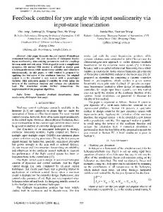
Fig. 1. Identification of voltage domains within the substrate. Assuming VC1 ≈ VC2 ≈ VC3 and VC4 ≈ VC5 ≈ VC6 , two voltage domains are created by the first and last three contacts. A coarse extraction is performed within each domain to reduce the computational complexity, followed by a fine extraction of those domains where the dominant current flow occurs.
ports is reduced by exploiting similarly biased regions within the substrate where each region represents a voltage domain. These regions are identified through differences in the transient voltage among the substrate contacts. An algorithm is introduced to determine these domains, reduce the number of ports, and create an equivalent port for each domain. The rest of the paper is organized as follows. Relevant background and existing extraction schemes are summarized in Section II. The proposed methodology and algorithm are described in Section III. Simulation results are presented in Section IV, and the paper is concluded in Section V. II. E XISTING E XTRACTION S CHEMES Two primary approaches exist that discretize the substrate into a 3-D RC mesh to determine the substrate impedances: finite difference method (FDM) [4], [2] and boundary element method (BEM) [5], [6]. FDM discretizes the substrate in differential form, resulting in a huge, but sparse matrix. Alternatively, the substrate is discretized in integral form by BEM, resulting in a significantly smaller, yet highly dense matrix. For BEM, only the ports into the substrate are discretized, making the computational complexity a strong function of the number of input ports. Another method to model the substrate is to use macromodels to represent the impedance between two ports on the substrate [7], [8]. Although computationally less expensive as compared to FDM and BEM, only limited accuracy can
376
i 2[t]
R2
L3 i out2[t]
i 1 [t] G L1
R1
i out1[t]
i 3[t]
im1 [t]= i 2[t]+i3[t]
R3
R m1 i out3[t] C 3
C2
i x[t]
i outm1[t] C m1
L2 i 6[t]
i 5[t]
i 1 [t]
i 7[t]
im3 [t]= i 6[t]+i7[t]
G
C1
L6 i 4[t]
L4
R5
R6
i out5[t] C 5
L7 i out6[t]
R7 i out7[t] C 7
C6
L1
R1
i out4[t] C 4 L8
i out1[t]
i y[t]
C1
i y[t] im2 [t]= i 4[t]+i5[t]+i8[t]
i 9[t]
i 8[t]
R m2
L m3 i outm2[t] C m2
L9
i 9[t] R9
R8
(a)
i outm3[t] C m3
R m3 L m2
L5 R4
i x[t]
L m1
i out8[t] C 8
L9
R9
i out9[t]
i z[t]
(b)
i out9 [t]
i z[t] C9
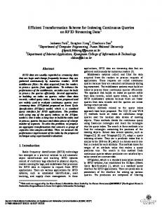
Fig. 2. Illustration of contact merging to reduce the number of input ports for substrate extraction process. The original ground network (a) contains nine substrate contacts. Three voltage domains are identified by merging C2 and C3 , C4 , C5 , and C8 , and C6 and C7 . The reduced network (b) has five substrate contacts.
be achieved. Other limitations are the requirement to obtain process-dependent fitting parameters and scaling these models for different geometries. Several techniques have been proposed to improve the efficiency of these approaches [9], [10], [11], focusing on the efficient solution of the algebraic equations obtained after the substrate is discretized by either FDM or BEM. The main limitation of both of these approaches, however, is the increase in computational complexity with circuit size, prohibiting the analysis of large scale circuits. A methodology is proposed in this paper to improve the complexity before the substrate is discretized. This improvement is achieved by reducing the number of ports for the extraction process, as described in the next section. III. I NPUT P ORT R EDUCTION The concept of voltage domains on the substrate is introduced in Section III-A. The algorithm to determine these domains and generate an equivalent port for each domain is described in Section III-B. A. Voltage Domains on the Substrate In a mixed-signal circuit, a common approach to bias the substrate is to use substrate contacts connecting the substrate to the digital ground network. The parasitic resistance and inductance of the ground network produce IR+L ∂i/∂t voltage bounces at each contact. If this voltage difference among several contacts is sufficiently small, the corresponding area on the substrate is effectively short-circuited, as illustrated in Fig. 1. In Fig. 1, C1 , C2 , and C3 produce the first voltage domain, and similarly, C4 , C5 , and C6 determine the second voltage domain. The dominant current flow occurs among the domains since the voltage variations within a domain is sufficiently small. These voltage domains can be exploited by reducing the number of ports to the substrate within a domain, allowing a coarse extraction, thereby improving the computational complexity. This reduction is achieved by merging all of the contacts into one equivalent contact within a domain. This equivalent contact is placed at the geometric mean of the merged contacts and the corresponding parasitic resistance and inductance of the ground network are updated to maintain accuracy, as described in the next section.
REDUCE-PORTS(extracted ground network, Vlim ) 1. for each node 2. for each child of the node 3. calculate Vdi f f (child) 4. end 5. identify bigChild 6. if Vdi f f (bigChild) ≤ Vlim 7. merge the children and parent 8. update R, L, and I[t] 9. end 10. end Fig. 3. Simplified pseudo-code to merge the substrate contacts on the ground network based on spatial transient voltage differences to reduce the number of ports to the substrate.
B. Algorithm to Reduce the Number of Ports The extracted ground network of the aggressor circuit is represented as a tree data structure where each substrate contact is a node and the root of the tree is an ideal ground. For each node (or contact) Ci , the algorithm requires the resistance Rci and inductance Lci of the ground network between the node and parent of the node, and the transient switching current Ici [t] injected into the node during a specific time window. For a large digital block, these current profiles can be obtained by pre-characterizing each standard cell within a library followed by a behavioral simulation of the circuit to extract the switching time of each cell. The current injected by those cells located between two contacts is shifted to the previous contact to prevent overly optimistic results. An example is shown in Fig. 2 to illustrate the inputs and outputs of the algorithm. The original ground network contains nine substrate contacts where each contact has a switching current profile Ici [t], and a resistance Rci and inductance Lci between the contact and parent of the contact. Simplified pseudo-code of the algorithm is provided in Fig. 3. The algorithm evaluates the voltage difference Vdi f f (child) between the contact and each child of the contact. The child with the greatest voltage difference is identified as bigChild. If this voltage difference is smaller than a user specified voltage Vlim , the parent and all of the children are merged into one equivalent contact, creating a voltage domain. This equivalent contact is placed at the geometric mean of the merged contacts. In Fig. 2, three voltage domains are determined by merging C2
377
180
160
160
140
140
120
120
Y location (μm)
Y location (μm)
180
100 80 60
100 80 60
40
40
20
20
0 0
50
100
150
0 0
200
50
100
X location (μm) (a)
150
200
X location (μm) (b)
Fig. 4. Physical location of the substrate contacts (represented by the circles) and the sense node (represented by the star sign) where the substrate noise is observed: (a) original 48 contacts before merging (b) nine equivalent contacts after merging when Vlim = 0.1 volts.
and C3 ; C4 , C5 , and C8 ; and C6 and C7 . The reduced network is composed of five substrate contacts. The resistance, inductance, and switching current of the equivalent contact are updated to maintain the original absolute voltage with the least error. The updated current is equal to the summation of the currents of the merged contacts. The resistance and inductance are updated based on bigChild for only the peak points of the transient current waveforms. For example, for Cm2 , this update is achieved as shown in (2), (3), and (4), assuming C5 is bigChild, e.g., Vdi f f (c5) is greater than Vdi f f (c8). Im2 [t] = I4 [t] + I5 [t] + I8 [t],
(1)
Ioutm2 [t] = I4 [t] + Iout5 [t] + Iout8 [t],
(2)
max(Iout5 [t]) , max(Iout4 [t])
(3)
max(∂(Iout5 [t])/∂t) . max(∂(Iout4 [t])/∂t)
(4)
Rm2 = R4 + R5 Lm2 = L4 + L5
Note that for Cm1 and Cm3 , the resistance and inductance are updated based on, respectively, C3 and C7 since C2 and C6 have a single child. IV. SIMULATION RESULTS The algorithm has been evaluated on an aggressor circuit consisting of a 4-bit carry select adder, a control unit, and scaled buffers at the output, designed in a 0.18 µm CMOS technology on a bulk type substrate. The ground network of the circuit consists of the first two metal layers, and originally contains 48 substrate contacts. The current profile for each contact is obtained from a transistor level simulation for a specific time window. The parasitic resistance between each contact is determined from the sheet and via resistances. The sheet resistances are 95 mΩ and 80 mΩ for the first and second metal layer, respectively, and the via resistance is 2 Ω. The REDUCE-PORTS algorithm is performed to identify the voltage domains on the substrate. Four different values (0.05 volts, 0.1 volts, 0.25 volts, and 0.4 volts) are used for
18
15
Original 48 contacts
Substrate noise (mV)
Merged to 9 contacts Merged to 1 contact
10
5
0
−5 14.5
15
15.5
16 16.5 Time (ns)
17
17.5
18
Fig. 5. Comparison of the substrate noise at the sense node before and after merging. The solid line represents the original circuit with 48 substrate contacts. The dashed and dotted lines represent, respectively, the reduced network with nine substrate contacts (Vlim = 0.1 volts) and a single substrate contact (Vlim = 0.4 volts).
Vlim to investigate the complexity versus accuracy tradeoff. For Vlim = 0.1 volts, nine voltage domains are identified. Each of these domains is represented by an equivalent substrate contact placed at the geometric mean of the merged contacts. The original physical location of the 48 substrate contacts and nine equivalent contacts after merging when Vlim = 0.1 volts are illustrated in Fig. 4. The substrate is extracted for the pre- and post-merging cases using SubstrateStorm. The noise is observed using Spectre at the sense node located 60 µm from the nearest substrate contact, as shown in Fig. 4. Note that the parasitic resistance between the substrate contacts on the ground network and the current profile of each contact are updated after merging based on the REDUCE-PORTS algorithm. The time domain noise waveforms observed at the sense node before and after merging are compared in Fig. 5. The waveform shape and peak magnitude of the substrate noise at the sense node after merging into nine contacts match the original noise voltage with a peak-to-peak error of 11% in the noise voltage. Note that the error increases to 70% if Vlim is increased to 0.4 volts,
378
TABLE I R EDUCTION IN THE NUMBER OF EXTRACTED SUBSTRATE RESISTORS , SUBSTRATE NOISE AT THE SENSE NODE , AND THE CORRESPONDING ERROR IN THE SUBSTRATE NOISE FOR DIFFERENT VALUES OF Vlim .
Original Vlim = 0.05V Vlim = 0.1V Vlim = 0.25V Vlim = 0.4V
−50
−60dB
−60 −63.4dB
Number of substrate contacts 48 15 9 3 1
−63dB
Number of extracted substrate resistors 1225 136 55 10 3
−65dB
Reduction
Noise Peak-to-peak 11.6 mV 10.5 mV 12.9 mV 15.3 mV 19.7 mV
– 9x 22.3x 122.5x 408.3x
Original 48 contacts
−66.4dB −70.7dB
−70 −80 −90
Magnitude (dB)
0
200
400
600
−59.6dB
−62.7dB
−65dB
800
1000
1200
1400
1600
1800
2000
−50 −60
−62.3dB
−66.3dB
Merged to 9 contacts −70.1dB
−70 −80 −90 0 −50 −60
−61.3dB
200
−58.4dB
400
600
−60.8dB
−63dB
800
−62.9dB
1000
1200
1400
1600
1800
2000
Merged to 1 contact
−64.6dB
at the sense node RMS At 200 MHz 0.68 mV -60 dB 0.61 mV -60.9 dB 0.72 mV -59.6 dB 0.78 mV -58.9 dB 0.87 mV -58.4 dB
Error at the sense node Peak-to-peak RMS At 200 MHz – – – 9.5% 10.3% 0.9 dB 11.2% 5.9% 0.4 dB 31.9% 14.7% 1.1 dB 69.8% 27.9% 1.6 dB
the transient voltage difference among substrate contacts, where each region represents a voltage domain. An algorithm is presented to determine these domains and generate an equivalent port for each domain, merging the remaining ports within that domain to improve the computational complexity of the extraction process. The impedance of the ground network is updated to maintain the original transient voltage after merging. A reduction of more than two orders of magnitude in the number of extracted substrate resistances is demonstrated with an error of less than 15% in the rms value in the time domain and around 1 dB error at the fundamental frequency of the substrate noise at the sense node.
−70
R EFERENCES
−80 −90 0
200
400
600
800
1000
1200
1400
1600
1800
2000
Frequency (MHz)
Fig. 6. Comparison of the spectrum of the substrate noise at the sense node before and after merging into nine contacts (Vlim = 0.1 volts) and a single contact (Vlim = 0.4 volts).
merging all 48 contacts into a single contact. The error in the rms noise over one period is 6% for nine contacts and increases to 28% for a single contact. The frequency domain characteristics are illustrated in Fig. 6. The average error at the fundamental frequency (200 MHz) and four higher harmonics is 0.42 dB when Vlim = 0.1 volts (the number of contacts is reduced to nine). For Vlim = 0.4 volts (where the number of contacts is reduced to one), the average error increases to 2.9 dB. Note that in this case, the error increases at the higher harmonics, for example, 6 dB at 1 GHz. Considering the number of substrate resistances, SubstrateStorm extracts 1225 resistors in the original system with 48 substrate contacts. Alternatively, when the number of contacts is reduced to nine, the number of extracted substrate resistances is 55, corresponding to a 20X reduction. The reduction in the number of extracted substrate resistors, and the corresponding error (peak-to-peak, rms, and at the fundamental frequency) in the substrate noise are listed in Table I for four different values of Vlim , demonstrating the accuracy versus complexity tradeoff. V. CONCLUSIONS A methodology is proposed to improve the efficiency of the substrate impedance extraction process for large scale circuits. Similarly biased regions on the substrate are identified through
[1] J. Briaire and K. S. Krisch, “Principles of Substrate Crosstalk Generation in CMOS Circuits,” IEEE Transactions on Computer-Aided Design of Integrated Circuits and Systems, Vol. 19, No. 6, pp. 645–653, June 2000. [2] B. R. Stanisic, N. K. Verghese, R. A. Rutenbar, R. Carley, and D. J. Allstot, “Addressing Substrate Coupling in Mixed-Mode IC’s: Simulation and Power Distribution Synthesis,” IEEE Journal of Solid-State Circuits, Vol. 29, No. 3, pp. 226–238, March 1994. [3] M. Badaroglu et al., “SWAN: High-Level Simulation Methodology for Digital Substrate Noise Generation,” IEEE Transactions on Very Large Scale Integration (VLSI) Systems, Vol. 14, No. 1, pp. 23–33, January 2006. [4] K. Fukahori and P. R. Gray, “Computer Simulation of Integrated Circuits in the Presence of Electrothermal Interaction,” IEEE Journal of SolidState Circuits, Vol. 11, No. 6, pp. 834–846, December 1976. [5] T. Smedes, N. P. van der Meijs, and A. J. van Genderen, “Boundary Element Methods For 3D Capacitance and Substrate Resistance Calculations in Inhomogeneous Media in a VLSI Layout Verification Package,” Advances Engineering Software, Vol. 20, No. 1, pp. 19–27, 1994. [6] R. Gharpurey and R. G. Meyer, “Modeling and Analysis of Substrate Coupling in Integrated Circuits,” IEEE Journal of Solid-State Circuits, Vol. 31, No. 3, pp. 344–352, March 1996. [7] D. Ozis, T. Fiez, and K. Mayaram, “A Comprehensive Geometrydependent Macromodel for Substrate Noise Coupling in Heavily Doped CMOS Processes,” Proceedings of the IEEE Custom Integrated Circuits Conference, pp. 497–500, September 2002. [8] H. Lan et al., “Synthesized Compact Models and Experimental Verifications for Substrate Noise Coupling in Mixed-Signal ICs,” IEEE Journal of Solid-State Circuits, Vol. 41, No. 8, pp. 1817–1829, August 2006. [9] N. K. Verghese, D. J. Allstot, and S. Masui, “Rapid Simulation of Substrate Coupling Effects in Mixed-Mode ICs,” Proceedings of the IEEE Custom Integrated Circuits Conference, pp. 18.3.1–18.3.4, May 1993. [10] E. Charbon, R. Gharpurey, R. G. Meyer, and A. Sangiovanni-Vincentelli, “Substrate Optimization Based on Semi-Analytical Techniques,” IEEE Transactions on Computer-Aided Design of Integrated Circuits and Systems, Vol. 18, No. 2, pp. 172–190, February 1999. [11] J. P. Costa, M. Chou, and L. M. Silveria, “Efficient Techniques for Accurate Modeling and Simulation of Substrate Coupling in MixedSignal IC’s,” IEEE Transactions on Computer-Aided Design of Integrated Circuits and Systems, Vol. 18, No. 5, pp. 597–607, May 1999.
379