Jun 30, 2004 ... The new ACM multistack is designed to carry six stacks ... was integrated into the
existing Caltrans manual cone body truck and was limited to ...
California AHMCT Research Center University of California at Davis California Department of Transportation
INTEGRATION AND TESTING OF A MULTISTACK AUTOMATED CONE MACHINE* Young-Chul Lee Wilderich A. White Steven A. Velinsky
AHMCT Research Report UCD-ARR-04-06-30-01
Final Report of Contract # 65A0066
June 30, 2004
*This report has been prepared in cooperation with the State of California, Business Transportation and Housing Agency, Department of Transportation through the Advanced Highway Maintenance and Construction Technology Research Center at the University of California at Davis.
Copyright 2011, AHMCT Research Center, UC Davis
ii Copyright 2011, AHMCT Research Center, UC Davis
Technical Documentation Page 1. Report No.
2. Government Accession No.
3. Recipient’s Catalog No.
CA06-0122
4. Title and Subtitle INTEGRATION AND TESTING OF A MULTISTACK
5. Report Date
AUTOMATED CONE MACHINE
6. Performing Organization Code
7. Author(s):
8. Performing Organization Report No.
June 30, 2004 AHMCT
Young-Chul Lee, W. A. White, S. A. Velinsky
UCD-ARR-04-06-30-01
9. Performing Organization Name and Address
10. Work Unit No. (TRAIS)
AHMCT Center UCD Dept of Mechanical & Aeronautical Engineering – 2132 Bainer Davis, California 95616-5294 12. Sponsoring Agency Name and Address
11. Contract or Grant RTA-65A0066 13. Type of Report and Period Covered
Final Report January 2000 – June 2004
California Department of Transportation Sacramento, CA 95819
14. Sponsoring Agency Code CALTRANS 15. Supplementary Notes
16. Abstract The Advanced Highway Maintenance and Construction Technology (AHMCT) Research Center has been developing robotic equipment and machinery for highway maintenance and construction operations. It is a cooperative venture between the University of California at Davis and the California Department of Transportation (Caltrans). The research and development projects have the goal of increasing safety and efficiency of roadwork operations through the appropriate application of automation solutions. This report describes the continuing development of automated equipment for deploying and retrieving traffic cones. In this latest phase of the project, the center has continued the development of the automated cone machine (ACM) through further testing and development of the first generation integrated prototype ACM and the design and fabrication of an integrated Multi-stack ACM developed to maximize the number of cones carried by the automated cone machine. Included in this report is the development of an improved control system for the retrieval arm which is a critical component used to pick up the traffic cone off the road. A first generation ACM prototype (ACM 1) is being used in tests and demonstrations on the highways of California. Operators using ACM 1 can place and retrieve cones without any set up and control the machine from within the confines of the cab. These machines can easily be run by a single operator and are very compatible with the process of closing a lane. The ACM 1 design was integrated into the existing Caltrans manual cone body truck and was limited to two stacks of 40 cones each. The new ACM multistack is designed to carry six stacks of 50 cones for a total of 300 cones. These machines are unambiguous demonstrations of the successful application of automation in a very demanding environment. This development work and the continued support of commercialization at AHMCT support the Caltrans goal of making these machines available to the maintenance operations. 17. Key Words
18. Distribution Statement
Automation, Robotics, Highway Maintenance, Traffic Cones, Highway Safety, Control Systems, Hydraulic
No restrictions. This document is available to the public through the National Technical Information Service, Springfield, Virginia 22161.
20. Security Classification (of this report)
20. Security Classification (of this page)
Unclassified
Unclassified
Form DOT F 1700.7 (8-72) (PF V2.1, 6/30/92)
Reproduction of completed page authorized
iii Copyright 2011, AHMCT Research Center, UC Davis
21. No. of Pages
22. Price
iv Copyright 2011, AHMCT Research Center, UC Davis
ABSTRACT The Advanced Highway Maintenance and Construction Technology (AHMCT) Research Center has been developing robotic equipment and machinery for highway maintenance and construction operations. It is a cooperative venture between the University of California at Davis and the California Department of Transportation (Caltrans). The research and development projects have the goal of increasing safety and efficiency of roadwork operations through the appropriate application of automation solutions. This report describes the continuing development of automated equipment for deploying and retrieving traffic cones. In this latest phase of the project, the center has continued the development of the automated cone machine (ACM) through further testing and development of the first generation integrated prototype, ACM-1, and the design and fabrication of an integrated Multi-stack automated cone machine, ACM-2, developed to maximize the number of cones carried by the automated cone machine. Included in this report is the development of an improved control system for the retrieval arm which is a critical component used to pick up the traffic cone off the road. The ACM-1 prototype is being used in tests and demonstrations on the highways of California. Operators using ACM-1 can place and retrieve cones without any set up and they control the machine from within the confines of the cab. These machines can easily be run by a single operator and are very compatible with the process of closing a lane. The ACM-1 design was integrated into the existing Caltrans manual cone body truck and was limited to two stacks of 40 cones each. The new ACM multistack, ACM-2, is designed to carry six stacks of 50 cones for a total of 300 cones. These machines are unambiguous demonstrations of the successful application of automation in a very demanding environment. This development work and the continued support of commercialization at AHMCT support the Caltrans goal of making these machines available to the maintenance operations.
v Copyright 2011, AHMCT Research Center, UC Davis
vi Copyright 2011, AHMCT Research Center, UC Davis
EXECUTIVE SUMMARY The Advanced Highway Maintenance and Construction Technology (AHMCT) Research Center has been developing robotic equipment and machinery for highway maintenance and construction operations. This report describes the continuing development of automated equipment for deploying and retrieving traffic cones. The need for mechanization of the cone handling process is well established throughout the world where automobiles are integral to society. Rising standards of living lead to higher standards of worker safety and tasks such as traffic cone handling require serious attempts to remove the worker from unnecessary exposure to hazards. Handling the traffic cones is physically demanding and exposes personnel to the hazards of working in and around live traffic. Since accidents do occur and the work must be accomplished, developing methods by which tasks can be achieved from within the relative safety of a vehicle is an obvious solution. This requires the application of mechanization and automation technology in order to give personnel a modicum of protection comparable to what the traveling public receives. By effective use of efficient and safe machines, the danger to crews and the public will be reduced. In this latest phase of the project, the center has continued the development of the automated cone machine (ACM) through further testing and development of the first generation integrated prototype (ACM-1) and the design and fabrication of an integrated multistack automated cone machine (ACM-2) developed to maximize the number of cones carried by the automated cone machine. ACM-1 was used in tests and demonstrations on the highways of California. Operators using ACM-1 can place and retrieve cones without any set up and control the machine from within the confines of the cab. It can easily be run by a single operator and is very compatible with the process of closing a lane. The ACM-1 design was integrated into the existing Caltrans manual cone body truck and was limited to two stacks of 40 cones each. The new ACM-2 is designed to carry six stacks of 50 cones for a total of 300 cones. With the single layer of two stacks of cones, the ACM-1 prototype machine is able to handle the vast majority of maintenance cone closures. Given the success of this concept, the addition of a means to extend the capacity of the machine was a natural development and is expected to increase the viability of automation in the lane closure process. The multistack system layout of ACM-2 is characterized by horizontally oriented cone stacks which are stored in multiple, vertical layers. Based on previous concept development work, a forklift unit design was chosen to raise and lower the cone stack layers within the storage framework. Successful integration and operation of the entire system can be mostly attributed to the simplicity of the forklift design. It effectively handles cone stack layers and supports the reconfigured main conveyor. vii Copyright 2011, AHMCT Research Center, UC Davis
AHMCT has been working directly with Caltrans maintenance and engineering to support the testing of ACM-1 in the real world of Caltrans maintenance operations. Various recommendations for design and operational improvements were identified and these are documented in the report. By maintaining the working prototype that is described, the intent has been to readily demonstrate its effectiveness to persons who would want to use the machine and those that might commercialize it. At the start of the project, the commercialization of the cone machine had progressed to the point of licensing the design. The University of California had licensed the ACM-1 design to the Clean Earth Environmental Group, LLC of Alabama and the project scope had anticipated the integration of the multistack into a commercial machine manufactured by Clean Earth. Although the company did not follow through on the development of the cone machine, other companies have continued to show interest and AHMCT has continued to support commercialization. These machines are unambiguous demonstrations of the successful application of automation in a very demanding environment. This development work and the continued support of commercialization at AHMCT supports the Caltrans end goal of making these machines available to the road maintenance operations.
viii Copyright 2011, AHMCT Research Center, UC Davis
TABLE OF CONTENTS ABSTRACT.................................................................................................................................... v EXECUTIVE SUMMARY .......................................................................................................... vii TABLE OF CONTENTS............................................................................................................... ix LIST OF FIGURES ...................................................................................................................... xii CHAPTER 1: INTRODUCTION ................................................................................................... 1 1.1 Background ............................................................................................................. 1 1.2 History of Development.......................................................................................... 1 1.3 Testing of ACM 1 ................................................................................................... 2 1.4 Multistack Design ................................................................................................... 2 1.5 Chapter Summaries................................................................................................. 3 CHAPTER 2: AUTOMATED CONE MACHINE OPERATION................................................. 5 2.1 Description of the basic Automated Cone Machine ............................................... 5 2.2 Main Conveyor Belt System................................................................................... 7 2.3 Stowage System .................................................................................................... 10 2.4 Lateral Conveyor Belt........................................................................................... 14 2.5 Drop Boxes ........................................................................................................... 16 2.6 Funnel System....................................................................................................... 18 2.7 Automated Control System................................................................................... 19 2.8 Power Systems ...................................................................................................... 20 CHAPTER 3: MACHINE FUNCTIONAL DESIGN CONSIDERATIONS............................... 23 3.1 Challenge to Automation of Cone Laying ............................................................ 23 3.2 Caltrans Fleet Experience ..................................................................................... 23 3.3 Caltrans Engineering Changes.............................................................................. 24 3.4 Operational Reliability.......................................................................................... 25 3.5 Recommendation for Hydraulic Power ................................................................ 25 3.6 Recommendation for Safe Stand by Mode ........................................................... 26 3.7 Recommendation for ACM Drop Box Operation................................................. 26 3.8 Recommendation for ACM Drop Box Road Clearance ....................................... 26 3.9 Recommendation for Cone Spacing ..................................................................... 27 3.10 Recommendation for Failure Diagnosis ............................................................. 27 3.11 Recommendation for Forward Pick Up .............................................................. 27 3.12 Recommendation for Standardization of Cone Design ...................................... 28 CHAPTER 4: MULTISTACK DESIGN...................................................................................... 29 4.1 High Capacity Machine History ........................................................................... 29 ix Copyright 2011, AHMCT Research Center, UC Davis
4.2 Need for a High Capacity Machine ...................................................................... 29 4.3 Consideration of a Reversed Orientation.............................................................. 31 4.4 Consideration of Alternatives to the Two Row Stowage System......................... 32 4.5 Consideration of Vertical Cone Stack Stowage.................................................... 32 4.6 Sizing of the Truck................................................................................................ 33 4.7 Review of Multistack Concepts ............................................................................ 34 4.8 Selected Forklift Design ....................................................................................... 37 4.9 Original Hinge Retraction Mechanism ................................................................. 39 4.10 Original Storage Framework............................................................................... 40 4.11 Operating Sequence ............................................................................................ 42 4.12 Integrated Storage Framework............................................................................ 43 4.13 Stack Storage sequence....................................................................................... 45 4.14 Summary of Multistack Design Development.................................................... 47 CHAPTER 5: RETRIEVAL ARM SYSTEM CONTROL .......................................................... 49 5.1 Introduction........................................................................................................... 49 5.2 Description of Retrieval Arm System................................................................... 49 5.3 New System .......................................................................................................... 53 5.4 Summary ............................................................................................................... 58 CHAPTER 6: RETRIEVAL ARM MODELING AND CONTROL ........................................... 59 6.1 System Modeling .................................................................................................. 59 6.2 Control .................................................................................................................. 62 6.3 Summary ............................................................................................................... 67 CHAPTER 7: RETRIEVAL ARM SIMULATION ..................................................................... 68 7.1 Desired trajectory.................................................................................................. 68 7.2 Proportional Controller ......................................................................................... 71 7.3 SOHL Controller................................................................................................... 75 7.4 TDDI Controller.................................................................................................... 80 7.5 Summary ............................................................................................................... 81 CHAPTER 8: RETRIEVAL ARM EXPERIMENT AND CONCLUSIONS.............................. 82 8.1 Parameter .............................................................................................................. 82 8.2 Proportional Controller ......................................................................................... 84 8.3 PID Controller....................................................................................................... 88 8.4 SOHL Controller................................................................................................... 93 8.5 TDDI Controller.................................................................................................... 95 8.6 Summary ............................................................................................................... 96 8.7 Conclusions........................................................................................................... 97 x Copyright 2011, AHMCT Research Center, UC Davis
8.8 Recommendations................................................................................................. 98 CHAPTER 9: SUMMARY AND CONCLUSIONS.................................................................. 100 REFERENCES ........................................................................................................................... 102 APPENDIX A............................................................................................................................. 104 APPENDIX B ............................................................................................................................. 110
xi Copyright 2011, AHMCT Research Center, UC Davis
LIST OF FIGURES Figure 2-1 The AHMCT Automated Cone Machine ACM-1 ...................................................... 5 Figure 2-2 Cone truck with cone body moved rearward .............................................................. 6 Figure 2-3 Main conveyor belt system ......................................................................................... 8 Figure 2-4 Cone support fixture ................................................................................................... 8 Figure 2-5 Infrared sensor mounts and lateral cone guides.......................................................... 9 Figure 2-6 Cone packer assembly................................................................................................. 9 Figure 2-7 Main conveyor belt power system ............................................................................ 10 Figure 2-8 Stowage system with covers removed ...................................................................... 11 Figure 2-9 Open and closed grippers.......................................................................................... 11 Figure 2-10 Gripper arm assembly at lateral conveyor belt ....................................................... 12 Figure 2-11 Gripper assembly at main conveyor belt system .................................................... 12 Figure 2-12 Detail of stowage system w/o covers...................................................................... 13 Figure 2-13 Stowage system operating without covers.............................................................. 14 Figure 2-14 Lateral belt system .................................................................................................. 14 Figure 2-15 Cone positioned on wing section ............................................................................ 15 Figure 2-16 Drop box system (Left side) ................................................................................... 16 Figure 2-17 Retrieval arm in cone retrieval position.................................................................. 17 Figure 2-18 Stowed drop box system and retrieval arm (Left side) ........................................... 17 Figure 2-19 Primary funnel system ............................................................................................ 18 Figure 2-20 Retracted primary funnel system ............................................................................ 19 Figure 2-21 Control interface for operator ................................................................................. 20 Figure 2-22 Hydraulic pump ...................................................................................................... 21 Figure 2-23 Hydraulic fluid reservoir and heat exchanger......................................................... 21 Figure 3-1 Scaled view of exposure during manual cone laying................................................ 24 Figure 4-1 Caltrans high capacity manual cone truck (Oakland Bay Bridge)............................ 30 Figure 4-2 Commercial cone truck with 400 cone capacity ....................................................... 30 Figure 4-3 High capacity cone truck used by Washington DOT................................................ 31 Figure 4-4 Revolving drum concept ........................................................................................... 35 Figure 4-5 Hinged rack configuration ........................................................................................ 36 Figure 4-6 Vertical lift concept................................................................................................... 37 Figure 4-7 Original forklift concept ........................................................................................... 38 Figure 4-8 Minimum stack support and hinge retraction requirements ..................................... 39 Figure 4-9 Retraction mechanism design concept...................................................................... 40 Figure 4-10 Original test bed multistack system assembly ........................................................ 41 xii Copyright 2011, AHMCT Research Center, UC Davis
Figure 4-11 Stack storage sequence ........................................................................................... 42 Figure 4-12 Storage framework before attachment of panels .................................................... 43 Figure 4-13 Storage framework with fork and mast before assembly........................................ 44 Figure 4-14 Top level filled and middle level empty ................................................................. 45 Figure 4-15 View showing hinges (cone shelves) retracted....................................................... 46 Figure 4-16 Top level filled and middle level filled................................................................... 46 Figure 5-1 ACM retrieval arm system hydraulic diagram.......................................................... 50 Figure 5-2 Potentiometer noise................................................................................................... 51 Figure 5-3 Nonlinearity of potentiometer .................................................................................. 52 Figure 5-4 New RA system hydraulic diagram .......................................................................... 54 Figure 5-5 Retrieval arm test bed ............................................................................................... 55 Figure 5-6 Adjustment effect...................................................................................................... 56 Figure 6-1 The hydraulic system ................................................................................................ 59 Figure 6-2 PID Controller........................................................................................................... 62 Figure 6-3 Nonlinear controller .................................................................................................. 63 Figure 7-1 Desired trajectory...................................................................................................... 69 Figure 7-2 Position of P controller with different valve coefficient........................................... 72 Figure 7-3 Controller output of P controller with different valve coefficient ............................ 72 Figure 7-4 Position of P controller with different supply pressure ............................................ 73 Figure 7-5 Torque of the hydraulic motor with different supply pressure ................................. 73 Figure 7-6 Position of P controller with different motor vane area............................................ 74 Figure 7-7 Torque of the hydraulic motor with different motor vane area ................................ 75 Figure 7-8 Position of SOHL controller with different mass and inertia ................................... 76 Figure 7-9 Position of SOHL controller with different β and CVi .............................................. 77 Figure 7-10 Position of SOHL controller with different return pressure ................................... 78 Figure 7-11 Pressure of Port A of SOHL controller................................................................... 79 Figure 7-12 Pressure of Port B of SOHL controller ................................................................... 79 Figure 7-13 Position of SOHL controller with noisy pressure transducer ................................. 80 Figure 7-14 Position of TDDI controller .................................................................................... 81 Figure 8-1 Flow Rate with Positive and Negative Command Voltage ...................................... 83 Figure 8-2 Pressure drop by hydraulic motor without load........................................................ 84 Figure 8-3 P controller................................................................................................................ 84 Figure 8-4 Motion range............................................................................................................. 85 Figure 8-5 Position data of P controller...................................................................................... 86 Figure 8-6 Robustness test: Inertia difference ............................................................................ 87 Figure 8-7 Robustness test: Temperature difference .................................................................. 88 xiii Copyright 2011, AHMCT Research Center, UC Davis
Figure 8-8 PID controller............................................................................................................ 89 Figure 8-9 Controller output without anti windup...................................................................... 90 Figure 8-10 Controller output with anti windup......................................................................... 91 Figure 8-11 Position data of PID controller ............................................................................... 92 Figure 8-12 Robustness test: Temperature difference ................................................................ 93 Figure 8-13 SOHL controller...................................................................................................... 94 Figure 8-14 Robustness test: Temperature difference ................................................................ 95 Figure 8-15 TDDI controller ...................................................................................................... 96 Figure 8-16 Test Result of three controllers ............................................................................... 97
xiv Copyright 2011, AHMCT Research Center, UC Davis
CHAPTER 1: INTRODUCTION 1.1 Background The Advanced Highway Maintenance and Construction Technology (AHMCT) Research Center has been developing robotic equipment and machinery for highway maintenance and construction operations. This report describes the continuing development of automated equipment for deploying and retrieving traffic cones. It describes the results from the testing of the first generation automated cone machine (ACM) prototype known as ACM-1, the development and fabrication of an integrated high capacity machine known as the ACM-2 and the development of an optimized control for operation of the retrieval arm which is an integral component of the automated cone machine. The need for mechanization of the cone handling process is well established throughout the world where automobiles are integral to society. Rising standards of living lead to higher standards of worker safety and tasks such as traffic cone handling require serious attempts to remove the worker from unnecessary exposure to hazards. Handling the traffic cones is both physically demanding and exposes the worker to the hazards of working in and around live traffic. Since accidents do occur and the work must be accomplished, developing methods by which tasks can be achieved from within the relative safety of a vehicle is an obvious solution. This requires the application of mechanization and automation technology in order to give personnel a modicum of protection comparable to what the traveling public receives. By effective use of efficient and safe machines, the danger to crews and the public will be reduced. 1.2 History of Development Previous phases of the machine development are reported in referenced AHMCT reports titled Development of an Automated Cone Placement and Retrieval Machine, and Development of a Prototype Automated Cone Machine and High Capacity Storage System. The earliest design efforts concentrated on the development of concepts that allowed mechanical transfer of the cone to and from the roadway. Collecting cones from the roadway was the biggest challenge and efforts focused on the development of a retrieval arm and funneling system that successfully gathered cones that were standing or tipped over. Patent 6,056,498, Apparatus for Retrieving Conical Roadway Warning Markers was assigned in May of 2000. The prototype known as ACM-1 was developed to integrate the cone retrieval and placement concept into a machine capable of working on the road in real world operations. Redesigned components installed on ACM-1 are known as the second generation components. ACM-1 is a fully functional system capable of supporting regular demonstrations and road tests by Caltrans crews 1 Copyright 2011, AHMCT Research Center, UC Davis
and other potential users. The design was integrated into the existing Caltrans manual cone body truck and was limited to two stacks of 40 cones each, a single layer of cones. 1.3 Testing of ACM-1 AHMCT worked directly with Caltrans maintenance and engineering to support the testing of ACM-1 in the real world of Caltrans maintenance operations. Various recommendations for design and operational improvements were identified and these are documented in the report. By maintaining the working prototype that is described, the intent has been to readily demonstrate its effectiveness to persons who would want to use the machine and those that might commercialize it. At the start of the project, the commercialization of the cone machine had progressed to the point of licensing the design. The University of California had licensed the ACM-1 design to the Clean Earth Environmental Group, LLC of Alabama and the project scope had anticipated the integration of the multistack into a commercial machine manufactured by Clean Earth. Although the company did not follow through on the development of the cone machine, other companies have continued to show interest and AHMCT has continued to support commercialization. 1.4 Multistack Design ACM-2 The new ACM-2, also known as the multistack, is designed to carry six stacks of 50 cones for a total of 300 cones. With a single layer of two stacks of cones, the ACM-1 is able to handle the vast majority of maintenance cone closures and the addition of a means to extend the capacity of the machine was a natural development and is expected to increase the viability of automation in the lane closure process. The multistack system layout is characterized by horizontally oriented cone stacks, which are stored in multiple, vertical layers. Based on previous concept development work, a forklift unit design was chosen to raise and lower the cone stack layers within the storage framework. Successful integration and operation of the entire system can be mostly attributed to the simplicity of the forklift design. It effectively handles cone stack layers and supports the reconfigured main conveyor. These machines are unambiguous demonstrations of the successful application of automation in a very demanding environment. This development work and the continued support of commercialization at AHMCT supports the Caltrans end goal of making these machines available to the road maintenance operations.
2 Copyright 2011, AHMCT Research Center, UC Davis
During the years of machine support, the AHMCT organization provided repeated demonstrations to Caltrans in all available venues. AHMCT has also maintained a presence on the web that continues to engender interest in this and other solutions in automation which enhance safety and efficiency in highway maintenance operations. In this latest phase of the project, ACM-1 was integrated into the Caltrans fleet and used in tests and demonstrations on the highways of California with several different crews. Operators using ACM-1 can place and retrieve cones without any set up and control the machine from within the confines of the cab. The automated machine can easily be run by a single operator and is very compatible with the process of closing a lane. 1.5 Chapter Summaries Chapter 2 describes the basic components of the automated cone machine and its subsystems. The functions of the machine components described are common to both the standard and the multistack cone machine. Chapter 3 documents the functional design considerations that are important for future automated cone machine designs. It describes potential improvements that should be considered in future design changes. Chapter 4 describes the multistack design development and describes the as built configuration. It reviews previous development efforts of the multistack concept and describes the as fabricated multistack machine. Chapters 5 through 8 detail the development of the controls for the retrieval arm. The chapters report on the effort to optimize retrieval arm control by modeling, simulation and then testing. Chapter 9 contains the concluding statements and recommendations.
3 Copyright 2011, AHMCT Research Center, UC Davis
4 Copyright 2011, AHMCT Research Center, UC Davis
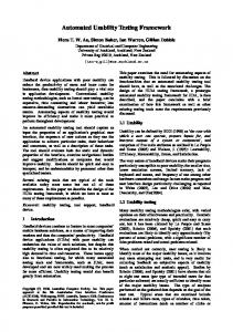
CHAPTER 2: AUTOMATED CONE MACHINE OPERATION In this chapter the basic operation of the ACM concept is described and the description of each subsystem is detailed. The system function is demonstrated in the machine known as ACM-1 which is shown in Figure 2-1.
Figure 2-1 The AHMCT Automated Cone Machine ACM-1
2.1 Description of the basic Automated Cone Machine The ACM-1 prototype was intended to be compatible with Caltrans cone laying operations and, as a result, it has been designed around the Caltrans cone body truck which is an effective machine for manual cone laying operations. Historically Caltrans had installed their cone body bed onto trucks with a GVW of about 4500kg (10000 lb), but since the 1990s, began using vehicles with a GVW of 6800kg (15000 lb). This was required because crews often found the 4500 kg limit inadequate for their needs and because the drive train components were more robust in the heavier vehicle. The vehicle used for the ACM-1 was a 1996 GMC HD 3500.
5 Copyright 2011, AHMCT Research Center, UC Davis
ACM-1 was developed around a slightly modified Caltrans cone body bed and was designed to be fully compatible with the manual cone laying operations. The thinking at that time was that this feature would be valuable in case of machine failure and would be easier for the customer, a cone laying crew, to integrate into their operations. In order to facilitate the placement of the automated machinery, the cone bed was moved back from the cab 43 cm (17 in), as shown in Figure 2-2. The main conveyor was shortened to open the space between the buckets. A minor problem was that clearance for the leaf spring shackles was required and infringed into the bucket area.
Figure 2-2 Cone truck with cone body moved rearward ACM-1 achieves placement and retrieval of cones through the coordinated operation of its four primary subsystem units: the stowage system, the lateral conveyor, the drop box assembly, and the primary and secondary funnels. Each subsystem is identified in Figure 2-1. The stowage system is located directly in front of the main conveyor between the buckets. It consists of two kinematically linked gripper arms, one dedicated to each cone stack. The grippers insert and remove cones, one at a time, to and from the stacks. The arms operate out of phase, moving back and forth between the front end of the cone stacks and the lateral conveyor. During drop off mode, the arms translate horizontally to pull a cone from the stack then follow a path of curvature to rotate the cone into a vertical, upright orientation before placing it on the lateral conveyor. The reverse sequence of cone manipulation is performed during retrieval mode. The lateral conveyor mounts inside the gap between the truck cab and the buckets and it spans the width of the cone body. The lateral conveyor consists of a series of lightweight belts and pulleys, which convey one cone at a time. Cones are placed onto the lateral conveyor by the stowage system gripper arms in an upright orientation and shuttled laterally to the left or the 6 Copyright 2011, AHMCT Research Center, UC Davis
right, depending upon which side cones are being deployed. Likewise, the lateral conveyor returns cones to the middle of the cone body to be stacked by the stowage system during cone retrieval. The drop box assembly is a retractable unit that deploys outward from the lateral conveyor during ACM-1 operation. It is stowed behind the cab during normal driving operation of the vehicle. The drop box assists in stabilizing cones during drop off mode. Once the lateral conveyor moves a cone out toward the side of the cone body, the cone falls through the drop box. The drop box helps preserve the upright orientation of the cone as it is placed on the road. The drop box also houses and supports the retrieval arm, which picks up cones off the road. The retrieval arm is activated during pick up mode only. The arm has a hand, which grasps the base of the cone and rotates it up and onto the lateral conveyor. The primary and secondary funnels are also used exclusively during cone retrieval. The secondary funnel is mechanically linked to the drop box. It opens when the drop box is deployed and retracts when the drop box is stowed. The primary funnel is independently actuated. Together, the funnels orient each cone to be picked up. It is certain the cone will be properly positioned after passing through the two funnels. The cone must be tipped over with the base end facing the drop box in order for the retrieval arm hand to grasp the cone and lift it from the road. The ACM-1 is highly versatile for use in traffic control operations. Right and left drop boxes make cone deployment possible from both sides of the vehicle. Four sets of funnels, on the front and back of each side of the ACM-1, allow for cone retrieval in the forward or reverse direction on either side of the truck. Overall, the ACM-1 demonstrates a high level of successful operation as a result of extensive fine tuning, testing and operation. It effectively achieves the same results as the manual operation procedure, while increasing safety by removing the worker from the bucket of the cone body. 2.2 Main Conveyor Belt System As on the Caltrans cone body, the ACM-1 is equipped with a longitudinal conveyor belt running down the center of the bed. It supports the horizontal stacks of cones and, in manual operations, the belt is activated by the operator and moves the stowed cones within his reach. On the ACM-1, this belt assembly is shortened to accommodate the stowage system and is a component of the main conveyor belt system. The cones are stowed in two adjacent stacks on top of the conveyor belt. A view of this system from the rear of the truck is shown in Figure 2-3.
7 Copyright 2011, AHMCT Research Center, UC Davis
Figure 2-3 Main conveyor belt system A cone support fixture is mounted on top of the belt and is shown in Figure 2-4. The purpose of the cone support fixture is to keep all the cones lined up in the longitudinal direction and keep the cone base plane perpendicular to the belt surface. This is accomplished by holding the first cone in each stack in the correct alignment. This alignment is required for proper interfacing with the stowage system.
Figure 2-4 Cone support fixture Two pairs of the photoelectric sensor mounts are located at the forward end of the main conveyor belt system as shown in Figure 2-5. The photoelectric sensors monitor the position of the first cone in each stack and are used to coordinate the transfer of the cones between the main conveyor and the stowage system. During retrieval, the cone stacks are moved one cone base thickness back to allow a cone to be added to the stack. During deployment the cones are moved forward to the end of the main conveyor belt system so that the stowage system can
8 Copyright 2011, AHMCT Research Center, UC Davis
remove the cones. Since both cone stacks are on the same belt, each operation mode alternates between the two stacks. Infrared Sensor Mount
Lateral Cone Guides
Figure 2-5 Infrared sensor mounts and lateral cone guides The lateral cone guides align the cones laterally on the main conveyor belt system to facilitate proper interfacing with the stowage system. These guides are composed of black Ultra High Molecular Weight (UHMW) Polyethylene formed to guide the cones to the proper lateral position and are mounted near the centerline of the cone as shown in Figure 2-5.
Figure 2-6 Cone packer assembly
9 Copyright 2011, AHMCT Research Center, UC Davis
The system shown in Figure 2-5 was changed to include an active component known as the cone packer shown in Figure 2-6. This mechanism added two functions during the transition from the main conveyor belt to the stowage system. During cone placement it restrains the next cone in the stack as the first cone is removed. During cone retrieval it pushes the just returned cone against the stack as it moves back to accept another cone. The main conveyor belt originally came equipped with its own electro-hydraulic power system as shown in Figure 2-7. The system is a standard configuration used in the Caltrans manual conebody. This system uses a 12 Volt, direct current (DC) motor that is directly coupled to a hydraulic power unit with an attached switching manifold. The manifold directs fluid to a hydraulic motor that drives the rear roller of the main conveyor belt. As part of the initial integration of the ACM 1 design, this power system was left intact to allow the standard manual belt operation in case the automated system is off and the operators are using the manual operating mode. Additional electrical circuitry was added to allow automatic control of this unit. Because of the high current draw, this power unit was eventually removed and the hydraulic motor was driven by the truck’s main hydraulic power system.
Figure 2-7 Main conveyor belt power system
2.3 Stowage System Centrally located between the two cone operator buckets is the stowage system as shown in Figure 2-8. The stowage system provides a cone transport link between the lateral conveyor belt system and the main conveyor belt system. This requires the stowage system to rotate a cone 90° since the cone is in an upright position on the lateral conveyor belt and is stored in a horizontal position on the main conveyor belt system.
10 Copyright 2011, AHMCT Research Center, UC Davis
Figure 2-8 Stowage system with covers removed During cone transport by the stowage system, the cone is firmly grabbed on the inside of the conical section with a set of expanding grippers. These grippers are pivot-mounted on an arm and linked by a double acting hydraulic cylinder. This cylinder’s action opens and closes the grippers as is shown in Figure 2-9.
Figure 2-9 Open and closed grippers The whole gripper arm assembly is pivoted on a roller assembly. This roller assembly moves linearly along a track to facilitate movement between the main conveyor belt and the lateral conveyor belt. Mounted above the track is a contoured surface that controls the pivot motion of the gripper arm assembly. This surface forces the gripper arm assembly to rotate to a horizontal position at the lateral conveyor belt and to a vertical position at the main conveyor belt
11 Copyright 2011, AHMCT Research Center, UC Davis
system. When the gripper arm assembly is at the lateral conveyor belt, it is located below the lateral conveyor belt surfaces so that the cone can be moved over the top of the grippers as shown in Figure 2-10. At this point, the grippers can either grip the cone from underneath as during the retrieval mode or release a cone that has just been placed on the lateral conveyor belt as during the placement mode.
Figure 2-10 Gripper arm assembly at lateral conveyor belt At the other end of the track, the gripper arm assembly is vertical at the bottom of the cone stack on the main conveyor belt system as shown in Figure 2-11. The gripper arm assembly at this location can again either grip a cone to be dispatched or release a cone that has been placed in the stack.
Figure 2-11 Gripper assembly at main conveyor belt system
12 Copyright 2011, AHMCT Research Center, UC Davis
Since there are two different stacks of cones on the main conveyor belt system, a gripper arm assembly with its track was manufactured for each stack. As previously described the cone stacks must be accessed alternately. The stowage system shown in Figure 2-12 was designed so that this alternating access motion is accomplished with the power of a single hydraulic vane motor. The gripper arm assemblies are linked via a single chain so that when one arm is at the lateral conveyor belt the other is located at the main conveyor belt system. To exchange the gripper arm positions, the hydraulic fluid flow to the vane motor is reversed and the grippers will be moved to the other end of their track. This combination of components allows for efficient and convenient cone operation between the two systems. A cone moving on the stowage system while in transition from upright to horizontal position is shown in Figure 2-13.
Figure 2-12 Detail of stowage system w/o covers
13 Copyright 2011, AHMCT Research Center, UC Davis
Figure 2-13 Stowage system operating without covers
2.4 Lateral Conveyor Belt The gap created by moving the cone body back (as previously shown in Figure 2-2) is occupied by the lateral conveyor belt system. This system spans the entire width of the truck and is responsible for the lateral motion of cones. The lateral conveyor belt interfaces with the stowage system in the middle of its length and terminates at the drop boxes on both ends. This is shown in Figure 2-14.
Figure 2-14 Lateral belt system The lateral conveyor belt is comprised of a total of ten notched groove belts, each 5 cm (2 in) in width. The belts are spaced so that they will contact the frontal and rear edges, usually the feet, of a cone placed on the system. The frontal and rear tracks always move at the same 14 Copyright 2011, AHMCT Research Center, UC Davis
rate and each equally support the weight of the cone. Any cone moving on the lateral conveyor belt is guided on both sides. The frontal guide spans the entire length of the lateral conveyor belt, while the rear guide is interrupted to allow for interfacing with the stowage system. The lateral conveyor belt operates in both modes of cone operation. During the placement mode, the cone is placed on the belts by the stowage system. After the stowage system gripper releases the cone, the lateral conveyor belt then moves the cone to the drop box at the operating side of the truck. During the retrieval mode the cone slides from the retrieval arm to the lateral conveyor belt which has its belts in motion to receive the moving cone. The cone is transported and then positioned on top of one of the two gripper arm assemblies of the stowage system. To stop the cone over the gripper, the lateral conveyor belt has gates with switches that sense the cone’s lateral position. These gates retract beneath the lateral conveyor belt and position the cone over alternating gripper assemblies as required. Also part of the lateral conveyor belt, there are two rotating sections, called ‘wings’, one located at each end of the lateral conveyor belt. The wing sections are lifted up or positioned down depending on the operating mode. During the cone dispatch mode the wing sections decline at a 30° angle to bring the cone as close to the ground as possible just prior to being positioned into a drop box. In the retrieval mode, the wing section is raised up to ensure correct placement of the retrieved cone onto the lateral conveyor belt. A small hydraulic cylinder positions the wing section. Figure 2-15 shows a cone at the transition to the wing section.
Figure 2-15 Cone positioned on wing section The lateral conveyor belt is powered by a single hydraulic rotary motor which rotates one main shaft of the lateral conveyor belt. Since all the belts are notched and roll over matching notched pulleys, with the front and rear pulleys connected by shafts, the entire set of ten belts 15 Copyright 2011, AHMCT Research Center, UC Davis
rotates in synch and at the same speed. The speed of a traversing cone on the lateral conveyor is set at approximately 0.6 m/s (2.0 ft/s). 2.5 Drop Boxes Located at both ends of the lateral conveyor belt is a drop box system, which is shown in Figure 2-16. The drop box system only operates during the cone dispatch mode, and also serves as a mounting base for the retrieval arm and secondary funnel system. The drop box system receives the cone from the lateral conveyor belt and guides the cone as it drops to the ground. Several guides are used to stabilize the cone as it contacts the road. The drop box with stabilizing guides is shown in Figure 2-16. Once the cone leaves the stabilizing guides of the drop box system, it has completed its journey from the main conveyor belt system to the road.
Figure 2-16 Drop box system (Left side) When not in use, the drop box system is automatically stowed by retracting the system within the confinement of the ACM body as shown in Figure 2-18. The retraction of the box includes all the attached subsystem components. Each drop box system is mounted on a track system that allows the drop box system to be lowered 25.4 cm (10.0 in) and moved out laterally 49.0 cm (19.3 in) from the stowed position. The position of the drop box system is controlled by the operator from within the cab. The second subsystem mounted to each drop box is the retrieval arm as shown in Figure 2-17, which also operates only during the retrieval mode. This system receives the cone in a horizontal orientation from the secondary funnel, grasps the flange at the base of the cone, raises the cone vertically and releases it onto the lateral conveyor belt in a vertical orientation. This component is a critical component of the retrieval process. It is able to quickly rotate between the forward and reverse directions to pick up a cone. This second generation design has made the 16 Copyright 2011, AHMCT Research Center, UC Davis
ACM-1 an extremely versatile cone retrieval machine. Optimizing the operation of the arm led to the development of the control system as described in Chapters 5 through 8.
Figure 2-17 Retrieval arm in cone retrieval position
Figure 2-18 Stowed drop box system and retrieval arm (Left side)
17 Copyright 2011, AHMCT Research Center, UC Davis
2.6 Funnel System The funnel system consists of a primary and secondary system. The primary funnel system is only used during the retrieval mode of operation and is the first subsystem encountered by a cone being retrieved from the road. The primary funnel system reorients the cones so that the cone enters base first as it approaches the secondary funnel. The ACM-1 has a primary funnel system mounted at all four corners of the truck. The four funnels are necessary for cone retrieval from either side of the ACM-1 and while driving forward or in reverse. Each primary funnel system is comprised of three main components, the gate mechanism, the vertical guides, and a tipping bar. The components are used to place the cones in the base first position. The gate mechanism is a metal plate that is able to freely rotate along its longitudinal top edge and has a locking device that can be activated to hold it in the vertical position. It is activated when necessary to either raise a cone that is pointed tip first to the ACM-1 or tip over a standing cone. The locking device is activated by a switch in the truck cab. The vertical guides consist of two bars that rotate cones as necessary to achieve the base first orientation. The tipping bar is used in conjunction with the gate to flip a cone over to the base first orientation. The left rear primary funnel system and its main components are shown and labeled in Figure 2-19.
Tipping Bar
Gate Mechanism Vertical Guiding Posts
Figure 2-19 Primary funnel system
18 Copyright 2011, AHMCT Research Center, UC Davis
Since the primary funnel system is only used during the retrieval mode, the ACM-1 must be able to retract the primary funnel system when not in use, and deploy it when needed for retrieval. This function is accomplished by activating the hydraulic vane motor to which each of the primary funnel systems is mounted. The tipping bar is designed so that it folds down during the primary funnel system retraction. It automatically unfolds to the open position when the primary funnel system is deployed. Figure 2-20 shows a retracted primary funnel system.
Figure 2-20 Retracted primary funnel system The secondary funnel system which only operates during the retrieval mode is fixed to the bottom of the drop box. The secondary funnel receives the cone from the primary funnel system and aligns it with the retrieval arm which then picks it up. On the ACM-1, a secondary funnel is oriented in both the forward and aft directions on both sides of the truck. The secondary funnel retracts automatically under the ACM-1 when the drop boxes are retracted. 2.7 Automated Control System The automated control system is made up of various sensors, actuators, and solenoids, coordinated by a commercially available micro controller. The model used in ACM-1 was the ZWorld Co. Little Giant C-Programmable Miniature Controller. This controller is based on a 16 bit Z180 microprocessor and is mounted in a metal enclosure located behind the seat in the truck cab. Sensors are incorporated throughout the subsystems. Besides the infrared sensors on the main conveyor belt system and the gate switches on the lateral conveyor belt that were previously described, sensors exist on other subsystems. The lateral conveyor belt has a sensor on each wing section to indicate if a cone has been dropped off into the drop box. The retrieval arms have sensors to indicate that a cone arrived and is ready for retrieval. Potentiometers are 19 Copyright 2011, AHMCT Research Center, UC Davis
used to determine the position of the arm. On the basic ACM-1, the control system controls the operation and timing of six hydraulic cylinders, one hydraulic motor, seven hydraulic vane actuators, 5 solenoids, and three DC motors, one of which in turn operates the main conveyor belt system hydraulics. The desired operating mode is defined by the operator in the truck cab. Figure 2-21 shows the various operator control interfaces. The micro controller is located behind the touchpad keyboard shown in the figure. This panel is mounted behind the driver’s seat and is normally not accessed except when trouble shooting. During normal operations the operator uses only a pendant with the four switches shown at the left of the keypad and the switch that operates the primary funnel gate. Allowing for safe operation and emergency situations, panic stop buttons were incorporated into the ACM-1. One button is present in each bucket of the cone bed and one is located in the cab.
Figure 2-21 Control interface for operator
2.8 Power Systems
Two sources of power are utilized by the ACM-1.
Some actuators require electrical
power while most motion systems utilize hydraulic fluid power. Electrical power is provided by the truck’s standard electrical system which is comprised of a 12 Volt DC battery and an alternator driven by the truck’s engine. The subsystems that
20 Copyright 2011, AHMCT Research Center, UC Davis
require electrical power include the main conveyor belt system motor, the drop box system drive motor, and the control system with all its associated switches and solenoids. Miscellaneous systems such as the standard sign board mounted on top of the ACM-1 also require 12V DC. The hydraulic power system uses a variable displacement rotary vane pump using fluid from a ten gallon reservoir located behind and above the cab. Six cylinders, one rotary motor and seven vane actuators are powered by this system. The pump is driven by the engine’s crank shaft via a pulley and two belts and is shown in Figure 2-22. The fluid tank is mounted below the truck’s sign board and above the rear of the truck cab. This location was chosen to allow for easier cooling. A heat exchanger with cooling fan was also mounted below the sign board. fan are shown in Figure 2-23.
The fluid reservoir and heat exchanger with cooling
Figure 2-22 Hydraulic pump
Figure 2-23 Hydraulic fluid reservoir and heat exchanger
21 Copyright 2011, AHMCT Research Center, UC Davis
22 Copyright 2011, AHMCT Research Center, UC Davis
CHAPTER 3: MACHINE FUNCTIONAL DESIGN CONSIDERATIONS
This chapter identifies significant functional design considerations that need to be considered in further development. The first sections describe general design issues and the results of extended testing of ACM-1 with Caltrans. Sections 3.5 through 3.12 list all the functional design issues that were found during the operation of the ACM-1 and the development for the functional specification of a multistack. This information is particularly relevant to the development of a next generation of commercialized machines. 3.1 Challenge to Automation of Cone Laying
As detailed in previously referenced development reports, the challenge of automating the cone laying process has existed for decades and many solutions have been attempted. The difficulty has been to integrate cost effective automation that is sophisticated enough to allow the user to operate with minimal attention to the machine. Cone laying vehicles must regularly stop to place flags and other warning features as part of the normal lane closure procedure. Present Caltrans operations use a relatively light cone truck like the ACM-1 and protect the manual cone laying vehicle with a heavy shadow truck with an attenuator. The cone machine then serves as the supervisor’s transport and, when not laying cones, it is often used to carry maintenance equipment and supplies. The cone laying operation requires intensive concentration by the operator who must be fully aware of the traffic and cannot be expected to regularly interact with the machine. Maintaining vehicle maneuverability, minimizing machine size, simplifying its design while reducing costs and increasing reliability are difficult challenges that require state of the art industrial control components. The dropping costs of control components and the increasing use of more sophisticated machines in the maintenance and construction industry will soon result in realization of automated lane closures. 3.2 Caltrans Fleet Experience
AHMCT provided regular demonstrations of ACM-1 to Caltrans in all available venues. Caltrans personnel always expressed enthusiastic interest in the machine and many were enticed to operate it for themselves after a few minutes of training. In 2003 the Caltrans organization put the ACM-1 prototype into their fleet in order to expose it more directly to personnel that might use it and formally make a request for a commercialized machine. AHMCT developed the operation and safety training procedure and provided continuous technical support during this time. A formal evaluation process over the course of a year demonstrated that the concept was completely viable. Based on the fleet experience, the 23 Copyright 2011, AHMCT Research Center, UC Davis
machine concept as designed is successful but improvements to the ACM-1 are required before it can be used consistently.
Figure 3-1 Scaled view of exposure during manual cone laying
One suggested improvement would be to meet the desire to minimize the width of the automated cone machinery when beginning a closure from a narrow shoulder. This reduction in width has the benefit of minimizing encroachment into passing traffic. The drop box and retrieval arm extend 483 mm (19 in) beyond the edge of the truck bed which is 102 mm (4 in) beyond where the basic cone is placed on the roadway. The ACM-1 funnel system adds another 152 mm (6 in) but can potentially be reduced to the width of the drop box and retrieval arm. Reducing the funnel width potentially requires the driver to position the truck more carefully when retrieving cones. Although reduction in width is obviously desirable, the scaled drawing in Figure 3-1 of a person placing a cone at the outer limits of where the ACM machinery is presently located demonstrates the desirable trade-off of using machinery instead of a person in the position exposed to high-speed traffic. 3.3 Caltrans Engineering Changes
Before placing ACM-1 into the fleet, three major changes were incorporated into the machine by the Caltrans engineering department responsible for equipment and these are described below. The first was to lengthen the space available on the main conveyor belt to allow it to carry 100 cones instead of the original 80. This was achieved by modifying the tail gate sheet metal to allow the cone tips to hang over the rear. Secondly, the electrical hydraulic pump system that was used to drive the main conveyor was removed and the hydraulic motor moving the main conveyor belt was then driven by the hydraulic power system of the machine. This detail is also discussed in Section 2.2. This 24 Copyright 2011, AHMCT Research Center, UC Davis
change requires that the truck engine be running and the hydraulic power system used to power the ACM-1 machine be engaged in order to move the belt forward and aft for loading the machine by hand. This change prevents the machine from being used in a manual mode independent of the automated machine. The benefit to the change is that the system does not draw the extremely high current required to run the electro-hydraulic pump. The typical cycle during the cone operation was 1 second on followed by 2 seconds off and it drew 160 amps when operating. Prior to this change, the high current draws on the whole truck were problematic when all the truck accessories such as the air conditioning system, electrical engine cooling fans, and arrow board lights were turned on. The solution implemented prior to this change was the addition of two high capacity reserve batteries that would keep the machine running during the cone laying operations. A third change was the removal of the arrow board and the addition of simple warning lights and a set of night work lights that were intended to allow night time operations. Lighting design requirements are critical to safe operations and are defined by Caltrans. The lighting chosen does not significantly impact the cone machine design except that night time operations require some light alongside the vehicle to see the movement of the cones in the various mirrors. 3.4 Operational Reliability
Although the limitations of the prototype ACM-1 were reviewed and discussed during training, the operators were periodically frustrated by machine failures. Operational reliability of a commercial machine would have to be much higher than that demonstrated by the prototype ACM-1. Any failures in the process of moving the cone in and out of the machine frustrated the users when on the highway even though the failures were infrequent and easily corrected. Failures were difficult to repeat and therefore difficult to diagnose since engineering personnel were not present during most failures and detailed documentation was not available. Based on experience, a reasonable minimum value of reliability for cone handling would be no more than one failure in 1000 events of cone placement or retrieval. With appropriate design changes, this value is achievable with the existing cones which are often problematic due to variations in dimensions and condition. Reliability tests will have to include the variations in environment temperatures which greatly affect the material properties of the typical traffic cone.
3.5 Recommendation for Hydraulic Power
Additional work was incorporated by Caltrans to increase the robustness of the gripper cylinders and the drive for the hydraulic power-take-off (pto) pump which is installed under the 25 Copyright 2011, AHMCT Research Center, UC Davis
forward pulley of the engine crank shaft. A serious attempt was made to find a more suitable location and mounting position for the pump but a thorough search of commercially available aftermarket components resulted in no improved solution. Integration of the necessary hydraulic power is very dependent on the truck chassis and is expected to require customized belt drive solutions unless a truck chassis with a standard pto configuration is available. Such a system must be able to operate continuously while the truck is stopped or moving at speeds of 0 to 10 mph while driven forward or backward. 3.6 Recommendation for Safe Stand by Mode
By keeping the power and force requirements of the individual actuators to a minimum, a significant level of safety is insured since the pinching and impact actions are unlikely to cause serious damage to limbs if caught. The prototype machine ACM-1 was used to demonstrate machine operations and was often operated in a static mode in which the cones were fed in and out of the system by a person standing next to the retrieval arm which moves quickly. It is strongly recommended that the commercial machine not be operational in this static mode. Various electrical signals were considered to place the machine in a safe state when a person was outside the vehicle. It is recommended that the machine be automatically put in a safe mode once the vehicle transmission is placed in the park position. 3.7 Recommendation for ACM Drop Box Operation
The ACM-1 drop box is driven in and out to the deployed position by an electric motor driving a screw and this process takes about 30 seconds. Serious consideration should be given to implementation of an actuation system that can deploy the drop box within a few seconds. This would allow the box to be retracted whenever the machine is stopped or placed in a safe mode. A person exiting the vehicle is then not subjected to tripping on the secondary funnels and will not have to walk around the cone handling machinery. 3.8 Recommendation for ACM Drop Box Road Clearance
Variations in road elevation may be problematic. The clearance of the drop box to the road is approximately two inches which is normally adequate and is not generally an issue. Periodically the road surface will vary by at least that amount such as when an overlay is being placed. The existing design has proven to be fairly successful at operating with the drop box dragging on the road or hanging 102 mm (4 in) above the road when the truck is driving on a sloping shoulder. Attention to this operating condition should be monitored, and adjustments to the design may be required based on user experience.
26 Copyright 2011, AHMCT Research Center, UC Davis
3.9 Recommendation for Cone Spacing
The ACM-1 control system uses a counter on the drive shaft to set the distance between cones. During development the control code was upgraded to take in account effects that caused the cone spacing to vary. When cones are fed out of the system the cones wait at the middle of the truck in two locations. Since the cones travel laterally at about 762 mm (30 in) per second the cone starting further away from the drop box must travel about 381 mm (15 in) further than the cone near the drop box. This represents a 0.5 second delay and will result in spacing variations unless accounted for in the control. As the cone truck speeds up the cone spacing will vary since a half second delay represents a different distance on the road when the truck is traveling at slow speeds versus when it travels at higher speeds. The .5 second delay represents 4.5 m (15 ft) at 16 km/h (10 mph). Various algorithms were placed in the code to minimize the spacing variations but ultimately a mechanical design change is required. To minimize cone spacing variation and increase the speed of machine operation, it is recommended that the cone be moved to the edges of the lateral conveyor where it will wait for the signal to drop into the box and be set on the road. Movement of the cone in and out of the stowage system will then not affect the placement distance between the cones, and the stowage system will then be free to get the next cone onto the belt immediately and not have to wait for the cone to clear the gripper. 3.10 Recommendation for Failure Diagnosis
Failures of individual components are to be expected and the ability to quickly find a faulty sensor or actuator is very important. Mechanical components must be designed with the robustness necessary to remove them as potential causes of failure. A record of functions should be stored in the controller so that a diagnosis can be made by reviewing the last sequence of steps. Although relatively simple in operation the machine has at least 20 sensors and 20 actuators. If the operator is unable to clearly define the failure mode, diagnosing a problem will not be simple and a diagnostic flow chart is a minimum requirement. Certain failures will be obvious to an operator or technician but many will not and personnel should not be expected to diagnose faults without significant assistance. 3.11 Recommendation for Forward Pick Up
Although most of Caltrans closures are removed by driving in reverse, operators should always have the capability to pick in the forward direction. The forward retrieval system designed into the ACM-1 is critical to its versatility since it requires no set up and is controlled by a switch from within the cab. 27 Copyright 2011, AHMCT Research Center, UC Davis
The ability of ACM-1 to readily configure itself to change from picking in reverse then forward allows an operator to pick up a cone that might have been knocked out of the line of cones. In such a case, the driver would interrupt the retrieval process in the rear direction by switching to forward retrieval, steering over and collecting the errant cone and then driving back into the protected lane. This operational feature avoids the need to have personnel exit the vehicle to remove an errant cone in most situations. Generally maneuverability of the machine is much greater when moving in the forward direction and the ability to pick in the forward direction is considered a very important feature. 3.12 Recommendation for Standardization of Cone Design
The dimensions and mechanical properties of a traffic cone are not consistent between manufactures and departments of transportation. Although the 711 mm (28 in) height is considered a de facto standard, Caltrans uses a 4.5 kg (10 lb) cone instead of the common 3.2 kg (7 lb) cone. The added weight is located at the base and makes the cone much more stable when subjected to the wind from passing traffic. During the course of ACM-1 development, Caltrans has modified its specification for traffic cones repeatedly to implement reflectors and impose other restrictions such as a minimum rigidity at high temperature. Independently of the ACM-1 development, Caltrans has also defined features such as the base dimensions critical to the design of the retrieval arm and other components in the machine. The ACM-1 designers repeatedly purchased a variety of 711 mm (28 in) cones and modified the machine to handle what might be considered the typical cone, but the specification for a traffic cone will have to be further defined to allow successful use of automated machinery. Although a cone machine manufacturer may always need to accommodate several cone designs, Caltrans and other users will be required to consider automated machine design when specifying their traffic cone specifications.
28 Copyright 2011, AHMCT Research Center, UC Davis
CHAPTER 4: MULTISTACK DESIGN
This chapter details the development of the integrated multistack machine known as ACM-2. 4.1 High Capacity Machine History
During the phase covered by this report, detailed design of a high capacity cone machine was accomplished. The project was defined with the objective of fabricating a roadworthy multistack machine that would maximize the cone carrying capacity. It was to be integrated with a commercially developed automated cone machine based on ACM-1. At the time, the ACM-1 design had been licensed by the Clean Earth Environmental Group, LLC and the multistack concepts were previously developed and evaluated in the phase of the machine development that was documented in the report titled Development of a Prototype Automated Cone Machine and High Capacity Storage System. 4.2 Need for a High Capacity Machine
An estimated 95 % of Caltrans closures require the use of less than 100 cones which can be accommodated by the standard sized ACM-1 which holds two rows of 40 to 50 cones in each row. Caltrans maintenance operations usually require shorter closures to deal with activities that require minimal access and short set up times. Longer closures are then achieved by doubling the stacks of cones on a standard manual cone truck and in the case of regular long closures, Caltrans uses high capacity trucks that can carry up to 270 cones and require two people in the rear to handle the cones. Such a vehicle is shown in Figure 4-1 and this particular vehicle was being used to set up long closures on the Oakland Bay Bridge on a nearly daily basis.
29 Copyright 2011, AHMCT Research Center, UC Davis
Figure 4-1 Caltrans high capacity manual cone truck (Oakland Bay Bridge)
Figure 4-2 Commercial cone truck with 400 cone capacity
30 Copyright 2011, AHMCT Research Center, UC Davis
In commercial operations the cone truck is often used to support lane closure operations, in which major roadwork is being done such as surface overlay operations. Such a vehicle is shown in Figure 4-2. Lane closures are often subcontracted to third parties that place and maintain the closure. An alternative design from the Washington State Department of Transportation is shown in Figure 4-3. This vehicle includes an attenuator shown in the stowed position at the rear of the vehicle.
Figure 4-3 High capacity cone truck used by Washington DOT
4.3 Consideration of a Reversed Orientation
As a result of the development of the ACM-1 around the concept of a manual cone truck, the placement of the place and retrieval system at the middle of the truck was considered a fixed requirement. A disadvantage to this configuration is that the machine must allow for sufficient space between the cone stack and the cab for the cones to be manipulated. Additionally many trucks have gas tanks, air tanks and other components located along the frame rail in this area.
31 Copyright 2011, AHMCT Research Center, UC Davis
If compatibility with manual operations is not required, the cone handling system could be reversed so that the automated machine is located over the rear end of the truck frame which greatly simplifies the packaging of the machine design. If the reversed design was to be considered, the maneuverability of the machine would first have to be tested. Forward pick up will be potentially problematic if one is trying to approach a cone at a steep angle. Multistack design considerations would not be greatly affected by a reversed design orientation. 4.4 Consideration of Alternatives to the Two Row Stowage System
An advantage to feeding cones out of the two horizontal stacks is that it can be done alternating left and right which in effect doubles the speed that cones can be removed from the stacks. It takes approximately one second to move the gripper from its forward position to its rear position at the cone stack where the next cone is accessed. A total cycle will require 2 seconds. By alternating the gripper motion, cones can be placed on the lateral conveyor in one second intervals. It takes about two seconds for a cone to travel to the drop box and be placed on the road. This allows a cone to be placed about every 3 seconds. When cones are retrieved, the cone is retrieved from the road fed onto the lateral conveyor and then stopped while the previous cone is put away by the stowage system. This retrieval function operates in parallel with the process of putting the cones away and normally allows a cone to be retrieved every 3 seconds. A possible improvement to the two row stowage system would be to place additional stacks side by side on the main conveyor. The changes to the lateral conveyor design would be significant and the added costs for a gripper at each row would have to be considered. A design alternative in which the stacks are placed at an elevated position was considered advantageous to the process of moving the cones in and out of the stacks. In a single layer configuration, the two stacks would be placed about 406 mm (16 in) above the lateral conveyor belt and about 254mm (10 in) forward of the present location. Since the cone stacks are located closer to the cab, more cones can be carried. The cone action would be smoother and therefore faster. Instead of translating the length of the cone and then rotating vertically to be placed on the lateral conveyor, the cone could be rotated while translating. The cone path cannot be a simple arc and would have to be achieved with a complicated linkage. This design was pursued during the design of the ACM-2 but was not completed. 4.5 Consideration of Vertical Cone Stack Stowage
Selection of a multistack configuration involved the process of trading off between several concepts. As previously noted, the decision was made to remain compatible with the
32 Copyright 2011, AHMCT Research Center, UC Davis
existing single layer design of ACM-1 but a variation using vertical cone stacks was reviewed in detail. Implementing a vertical stacking design would require a significant change to the stowage system but the remainder of the cone machine would be unchanged. Upon initial inspection this method of packing the cones is appealing and familiar since the cones are often palletized in this configuration and they are often found on a truck in this orientation (as shown in Figures 4-1 and 4-3). Two negative features rule out this configuration. The first is that cones are not stable when standing in a tall stack and must be supported to keep from tipping over. Stack height is limited by the load on the bottom cone of the stack and significant distortion will occur to the cone at the bottom cone of the stack. Additionally, each cone needs to be lifted up and over the next cone which requires a large handling mechanism that adds design complication. Additionally, the cycle time is significantly increased and would vary depending on the number of remaining cones in the stack. The packing of cones is more efficient in the horizontal orientation since every nested stack of cones requires 711 mm (28 in) clearance for the first cone followed by approximately 51 mm (2 in) per each additional cone. Various vertical stack layouts were considered and ruled out. A stack lying on its side is relatively stable but dealing with more than one layer is the challenge imposed by the horizontal multistacking concept. Any potential advantages to vertical stacks were investigated and ruled out. 4.6 Sizing of the Truck
The cab and chassis sizing was based on three factors that limited its selection. The gross vehicle weight was to be below 11,818 kg (26000 lb) so that the operator would only need a standard driver license to operate the vehicle. The wheel base needed to allow the drop box and funnel system to fit between the forward and rear axles and the drop box had to have sufficient space behind the cab to retract against the frame. The top surface of the truck frame was to have a maximum height of 860 mm (34 in) above the road and was limited to 860 mm (34 in) wide at the lateral conveyor mounting point. Fundamentally the truck required is similar to the high capacity manual cone laying vehicles described in section 4.2. The basic ACM-1 was installed onto a 1996 GMC 3500 truck with a gross vehicle weight of 6818 kg (15000 lb). The overall width of the truck is 2286 mm (90 in) which is based on the manual cone body developed by Caltrans. It has dual wheels in the rear and the axle width is approximately 2235 mm (88 in) at the tire walls. The truck purchased for the ACM-2 was a 2003 International model 4200. It has a wheel base dimension of 4293 mm (169 in) and the frame height is nominally 838 mm (33 in). 33 Copyright 2011, AHMCT Research Center, UC Davis
One feature that imposed complicating space constraints was the addition of a vertical exhaust stack behind the cab. Cabs of this class of truck are much larger than the GMC 3500 and the overall width as defined by the cab and rear axle is 2438 mm (96 in). 4.7 Review of Multistack Concepts
In previous development work several reasonable concepts were designed and they are reviewed to allow visualization of the challenge. 4.7.1 Revolving Drum Concept
The revolving drum concept, shown in Figure 4-4, used a cylindrical shaped drum to store cone stacks. The rotation axis of the drum was oriented along the length of the truck bed and centered above the main conveyor belt. The drum container design included several slots, each large enough for two cone stacks. By rotating the drum, the slots were positioned directly above the main conveyor to store or dispense cones. During cone retrieval, the main conveyor inserted cones into the slotted openings. Then features inside the drum clamped and secured the stacks. Actuation of the drum was achieved using a minimum of one rotary motor and several linear actuators, which were used to raise the drum. Raising the drum was necessary to avoid interference with the main conveyor while the drum rotated. The revolving drum design minimized manipulation of the cone stacks, which was advantageous. It also offered high cone storage capabilities. Expanding the drum design potentially enables it to carry up to ten cone stacks. However, increasing the cone carrying capacity of the drum was to likely exceed the weight limitations of most maintenance trucks and required too large a vehicle. The necessary cone body modifications included decreasing the storage bin size depending on the drum diameter. However, by carefully designing the drum support features, the main conveyor required little redesign work. Another disadvantage of the design was the overall size and excess drum volume. The void space in the center region of the drum was inevitable due to the spatial layout configuration of the cones. The overall mechanical complexity was moderate and controlling the drum rotation posed potential problems due to weight imbalances created by the cone stacks.
34 Copyright 2011, AHMCT Research Center, UC Davis
Figure 4-4 Revolving drum concept
4.7.2 Hinged Rack Concept
The hinged rack concept consisted of two, symmetric cone storage racks, one on each side of the main conveyor, as illustrated in Figure 4-5. Each rack consisted of a double stack support framework, rotary motion actuators and additional features to secure the cones. The racks rotated between a stored position above the cone body storage bins and a deployed position above the main conveyor. Like the revolving drum design, the main conveyor fed cones in and out of the deployed racks during cone retrieval and placement operations, respectively. The hinged rack concept offers a solid option for tripling the cone capacity of the maintenance vehicle by storing six stacks. However, configuration limitations prevented the design from being expanded to store more than six stacks. The low mechanical complexity simplified the detail design and control development. Moderate cone body modifications were required for system integration. The main conveyor configuration likely needed changes and, depending upon the location of the rack hinge point, portions of the storage bins also required modification. Weight imbalance posed a potential problem with the design. With one rack full of cones and the other empty, an unsymmetrical loading condition was created, which amounted in a 363 kg (800 lb) load difference across the width of the vehicle. For short operations weight imbalance raised little concern. However, it was undesirable for this condition to exist for extended periods of time, especially while traveling at highway speeds.
35 Copyright 2011, AHMCT Research Center, UC Davis
Figure 4-5 Hinged rack configuration
4.7.3 Vertical Lift Concept
The vertical lift design, depicted in Figure 4-6, stored cone stacks in an array configuration directly above the main conveyor. An actuated vertical lift was required to raise and lower stacks between an overhead storage framework and the main conveyor during cone storage and retrieval, respectively. The main conveyor was used to build and properly position the cone stacks on the lift prior to storing them. The lift then raised and positioned the cone stacks in the framework where securing features were used to constrain and support the cones. During system operation, the storage framework was progressively filled with cone stacks one level at a time, beginning with the top level and proceeding down. The stacks were retrieved in the reverse order.
36 Copyright 2011, AHMCT Research Center, UC Davis
Figure 4-6 Vertical lift concept
The vertical lift design increased the cone load of the vehicle to between four and eight cone stacks. Height and weight constraints limited a larger cone capacity. Implementing the vertical lift required minimal modifications to the storage bins but a significant redesign of the main conveyor. The lifting mechanism introduced a potentially high level of mechanical complexity into the system. Physical constraints of the system also complicated the method of securing the stacks. The linear motion of the lift, and the potential for coupling the cone retention features, reduced the control complexity. However, the time required to operate the system was evidently longer compared to the other concepts. Though the weight of the framework and lift were a concern, weight imbalance problems were eliminated by storing the cones along the middle of the cone body above the main conveyor. 4.8 Selected Forklift Design
A process of design selection used in the earlier phase of high capacity storage system development resulted in the selection of a vertical lift concept that implemented a forklift design to move the stacks vertically. This design was implemented in the integrated multistack machine. The design details as originally developed are described and then compared to the final design as fabricated in the development.
37 Copyright 2011, AHMCT Research Center, UC Davis
The forklift design concept was based upon the fundamental design of industrial forklifts. The components of the forklift included forks, a carriage, masts and a cylinder assembly. The concept is depicted in Figure 4-7 without the masts. The cylinder would mount to the truck frame toward the back end of the cone body. The carriage would be placed below the cone stacks and adjacent to the cylinder. A leaf chain would couple the carriage to the cylinder piston. Activation of the cylinder raised and lowered the carriage. The channel masts were to be mounted on both sides of the carriage. Roller bearings attached to the sides of the carriage would travel inside the channels, which constrained the motion of the carriage to the vertical plane. The forks would be rigidly attached to the carriage and cantilevered forward to support the entire length of the cone stacks. A split belt design was identified as the best main conveyor configuration. Two narrow, parallel belts could be used to support and convey each stack. Interference conflicts between the conveyor belts and the carriage led to a conveyor design which mounted to the forklift unit. There were a number of positive aspects about the forklift concept. The design was simple, yet robust. The means of actuation was also simple, requiring only one cylinder to achieve vertical motion of the forks. The forklift design also lent itself to many options for using commercially available parts and equipment. Since the forklift functioned as a dedicated vertical lift, the design was easily expanded for larger systems.
Figure 4-7 Original forklift concept
38 Copyright 2011, AHMCT Research Center, UC Davis
Negative aspects of the forklift design included high weight due to hefty components, specifically the large size of the masts and cylinder. An independent retention system was also needed to secure the stacks in the structural framework. A minimum configuration for the retention system is shown in Figure 4-8 with the hinges supporting the resting cones. These hinges are also known as the cone shelf and are the critical support components for the multistack. By supporting the outer edges of the cone a gap between hinges allows the fork lift assembly to clear as it returns to the normal state at the truck bed level.
Cone rubber base pad
Retraction of hinge inside 31.2 mm (1.2 in) gap
Minimum 25.4 mm (1.0 in) l Figure 4-8 Minimum stack support and hinge retraction requirements
4.9 Original Hinge Retraction Mechanism
The original retraction mechanism concept consisted of a backward driven slider crank mechanism for rotating the hinge. The mechanism was designed to actuate the free leaf of the hinge up and down from the front end of the structural framework. The retraction mechanism design shown in Figure 4-9 leant itself to an interconnected configuration that required only a single cylinder to actuate all the hinges. To achieve this result, a spring component was added as part of each linkage to introduce some compliance into the mechanisms.
39 Copyright 2011, AHMCT Research Center, UC Davis
Since only the
hinges without cones were required to move, the presence of cones would cause the spring to compress on the hinges that were to not move. A connecting framework was also designed to link the mechanisms to the cylinder. In the integrated design this concept was replaced by a mechanism using an actuator for each level of cones.
Figure 4-9 Retraction mechanism design concept
4.10 Original Storage Framework
The storage framework is a structural weldment to which other components are attached. Along with a few other structural members that are added to the cone body to assist in supporting the multistack components, it is constructed onto the vehicle first. The framework and components of the original test bed are shown in Figure 4-10. The retention system is made of three sets of components: the retention hinges, the retraction mechanisms and the actuated mechanism framework. The eight continuous hinges mount to the cross members of the storage framework and the actuated mechanism frame mounts to the front end of the storage structure. The mechanisms assemble onto the actuated framework and connect to the front end of the hinges.
40 Copyright 2011, AHMCT Research Center, UC Davis
Hinges (8)
Cylinder Retraction Mechanism Framework Forks Storage Framework Idler Assemblies
Drive Shaft
Masts Carriage
Figure 4-10 Original test bed multistack system assembly
The forklift consists of three separate components: the lift cylinder, the carriage with supporting masts, and the forks. With the exception of the forks, all the components are placed rearward of the storage framework. The lift cylinder and mast weldment mount to the truck frame and attach to the storage framework. The carriage connects to the lift cylinder and assembles inside the mast weldment. The forks mount to the carriage. The main conveyor attaches to the forklift unit. An idler assembly fastens to the front of each fork and the drive shaft assembly mounts to the rear end of both forks. Two timing belts are assembled and wrapped around the top and bottom of the fork along its length.
41 Copyright 2011, AHMCT Research Center, UC Davis
4.11 Operating Sequence
The multistack operating sequence is best described as a highly linear, sequential procedure. While rapid execution is physically limited, system control is greatly simplified. Stack storage is described below and stack retrieval is the opposite process. The system enters the storage mode during ACM cone retrieval. The main conveyor assists in stacking cones during retrieval from the road and once the stacks reach maximum size, it aligns the front of the stack approximately 7.6 cm (3 in) behind the axis of the front conveyor pulleys. The forklift is then powered to raise the stacks into the storage structure. Upon activation of the forklift unit, the retraction mechanisms are actuated to retract the hinges and clear the vertical envelope for the cones. The stacks are lifted to the highest unoccupied layer in the storage structure and continue above the retracted hinges. The retraction mechanisms are then reverse actuated to unfold the hinges. The forklift then slowly lowers. The forks pass between the deployed hinge leaves, transferring the stacks from the forks to the hinges, and then return to the truck bed level. Figure 4-12 demonstrates the system storage sequence. Storage mode operation continues throughout cone pick up until all storage levels are filled, including the main conveyor.
Step 1: Hinges retracted Hinges Step 2: Cone stacks raised
Forks
Cone Step 3: Hinges lowered Step 4: Cone stacks lowered Figure 4-11 Stack storage sequence
42 Copyright 2011, AHMCT Research Center, UC Davis
4.12 Integrated Storage Framework
The storage framework is shown in Figure 4-12. The structural components seen are the primary structural members that support the weight of the cone stacks and attach members to the truck chassis. A sub frame of two lateral box beams and one c-channel beam is bolted to the truck. These members are 102 mm (4 in) tall and have longitudinal spacers welded between. The box beams are centered about the rear axle of the truck. The storage framework itself consists of three longitudinal 102 x 102 mm (4 x 4 in) box beams which are welded to the sub frame and support the vertical members and cone shelf brackets.
Figure 4-12 Storage framework before attachment of panels
The storage framework is enclosed with the sheet metal as seen in Figure 4-13. The sheet metal provides the shear loading of the structure and encloses the framework to keep the cone stack inaccessible to personnel. Since the typical layer of two stacks will have the weight of 454 kg (1000 lb), the machine forces necessary to move the stacks vertically are potentially injurious and the lift mechanism should be shielded.
43 Copyright 2011, AHMCT Research Center, UC Davis
The design of the bins located along side the storage housing is not critical to the function of the machine and they were configured to carry items typically found on a cone truck. The forward bin is potentially useful to carry a standing person in case of machine failure. This might be used if cones need to be quickly collected to open a lane. A means to belt the person to the vehicle would have to be added.
Figure 4-13 Storage framework with fork and mast before assembly
The fork assembly shown is similar to the original test bed design. It has been reconfigured to ensure that all the components are located above the frame rails of the truck. This sub-assembly is installed at the rear of the truck.
44 Copyright 2011, AHMCT Research Center, UC Davis
4.13 Stack Storage Sequence
In the following views the sequence of stack storage as described in Section 4.11 is represented on the integrated machine. Various components such as the fork lift cylinder are not installed. Figure 4-14 represents a filled upper layer and empty mid level. In the case of cone retrieval, the ACM-2 system would fill the two stacks on the fork. The hinges or cone shelves at the mid level would be retracted as shown in Figure 4-14 and more closely in Figure 4-15. The fork lift would raise the filled stacks to the middle level. The cone shelves would be activated and the fork would return to the lowest resting position.
Figure 4-14 Top level filled and middle level empty
45 Copyright 2011, AHMCT Research Center, UC Davis
Figure 4-15 View showing hinges (cone shelves) retracted
Figure 4-16 Top level filled and middle level filled
46 Copyright 2011, AHMCT Research Center, UC Davis
4.14 Summary of Multistack Design Development
During this phase of development, all design concepts for multistacking have been reviewed and the use of the vertical stacking concept was confirmed to be the most effective and efficient method to expand the capacity of an automated cone machine such as ACM-1. The ACM-2 multistack concept based on the fork lift design is expected to be relatively easy to implement as an add-on module to the basic ACM-1. Several design features of the fork lift concept are ideal for commercialization. Cylinders, chains and rollers used to actuate and support the system are readily available in the commercial market. The fork design itself is relatively simple and, depending on customer needs, it is expected that several different lengths could be made to be installed on different length truck chasses. Design efforts in this latest iteration optimized the packaging of the system and have increased it robustness. By redesigning the cone shelf and its system of actuation, cone stacking density has been increased. The added components found on the ACM-2 will add costs to the concept as originally demonstrated on the test cone body. The benefits that result in improvement to function and packaging are considered worth the added costs.
47 Copyright 2011, AHMCT Research Center, UC Davis
48 Copyright 2011, AHMCT Research Center, UC Davis
CHAPTER 5: RETRIEVAL ARM SYSTEM CONTROL 5.1 Introduction
Although the Retrieval Arm (RA) is able to consistently pick up the cones from the road, it occasionally has problems positioning them on the lateral conveyor. The RA system operates quite differently under different temperatures. This is primarily due to changes in system characteristics caused by large changes in temperature. At high temperatures, the oil viscosity decreases, increasing the flow rate, and as a result the RA moves faster and tends to overshoot with the present control. At low temperature, the opposite is true. Also cones are more flexible at high temperatures. This increased flexibility causes the cone to flap back and forth once the RA comes to rest, even from the same rotating speed. Consequently, settling time of the cone increases the total time of the retrieval cycle. The purpose of this effort is to improve the robustness and the controllability of the RA system. With a more sophisticated control system, the RA system can operate more consistently without being affected by temperature, move with smoother starts and smoother stops, and complete an operation cycle with a shorter time. Chapter 6 discusses the problems of the present RA system in detail and introduces the new system and test bed. Chapter 6 provides the modeling of the RA system and introduces three controllers. Chapter 7 discusses the simulation of these controllers, and Chapter 8 represents the experimental procedure and discusses the experimental data of the various controllers. It discusses the results of the experiments and presents conclusions and recommendation of this study. 5.2 Description of Retrieval Arm System
The RA system is attached to the side of the drop box and is activated by a single-vanelimited-rotational hydraulic motor. The hydraulic diagram is shown in Figure 5-1.
49 Copyright 2011, AHMCT Research Center, UC Davis
Potentiometer
To Z-World ADC
Single Vane limited rota ion Hydraulic motor
Four way Three position valve for the direction To Z-World Relay Board
To Z-World Relay Board
From the pump
Two way Two position valve for he speed
To Z-World Relay Board
Fixed Orifice
Needle valve for he flow rate
Reservoir
Figure 5-1 ACM retrieval arm system hydraulic diagram
5.2.1 Hydraulic Valve
The motor is controlled by two valves. One is a four-way, three-position valve controlling direction, and the other is a two-way, two-position valve that controls speed. With this configuration, there are only two different flow rates. Each flow rate is set for optimal transient response and minimal steady state position error. The manually adjusted needle valve sets the maximum flow rate of the RA system. There is also a delay between the shut off signal from the controller and the actuator shut off, because of the spool dynamics. Since 0.5 cubic centimeters (0.0306 in3) of displacement causes a one-degree rotation of the hydraulic motor, a few milliseconds shut-off delay can result a few degrees offset. To compensate for this delay, the controller sends a shut-off signal when the RA is at some prescribed distance from the release position. However, the position for sending the shut-off signal depends on the temperature of the hydraulic oil.
50 Copyright 2011, AHMCT Research Center, UC Davis
5.2.2 Potentiometer
The arm position is read with a potentiometer, which is an inexpensive way to measure absolute angular position. However, the potentiometer has several drawbacks. The first drawback is wear of the wiper as it moves across a wire or carbon. The second drawback is that the potentiometer sends data as an analog signal, so it is susceptible to noise. The last drawback is that errors from the signal conditioning and from the Analog-Digital (A/D) converter make the data from the potentiometer unreliable. The noise and the A/D conversion error may be suppressed by averaging several samples. Figure 5-2 shows the potentiometer noise relative to encoder data and Figure 5-3 shows the nonlinearity of the potentiometer. The maximum noise range is about 0.6 degrees and the maximum offset of nonlinearity is about 7 degrees. Potentiometer Noise
182 181.9 181.8
Position (degree)
181.7 181.6 181.5 181.4 181.3 181.2 181.1 181 22.5
22.6
22.7
22.8
23 22.9 23.1 Time (sec)
Figure 5-2 Potentiometer noise
51 Copyright 2011, AHMCT Research Center, UC Davis
23.2
23.3
23.4
23.5
Potentiometer .vs. Encoder
300
Position (degree)
250
200
150 encoder potentiometer 100
50 1000
2000
4000 Encoder Count
3000
5000
6000
7000
Figure 5-3 Nonlinearity of potentiometer
5.2.3 Control
Essentially, all sensors should be monitored and all actuators should be controlled all the time for real time control. A single controller can only execute instructions in series. However, since controller execution time is much less than a physical action execution time, a controller can appear to monitor all sensors and to control actuators in parallel. This is done with a multitasking program. Costatements, a built-in function in the Z-World controller, allow the controller to run several tasks by cooperative multitasking, which means that each task relinquishes control when it is waiting, thereby allowing other tasks to proceed. One program has several Costatements in a ‘while’ loop. Typically, each Costatement consists of command groups that activate an actuator, monitor a sensor and execute other commands. If the condition has not been met, the running Costatement gives up control and the next Costatement in the sequence executes. If the condition within a Costatement is satisfied, the controller initiates the next group of commands. Therefore, several actuators may be running simultaneously but the controller monitors only one sensor at a time, checking if a condition has been met. Costatements have three advantages: [3] 1. Much easier communication between tasks.
52 Copyright 2011, AHMCT Research Center, UC Davis
2. Greater predictability of mutual task interaction. 3. Much simplified programming. The drawback of Costatements is in the monitoring intervals. If a group of commands takes longer to execute, the currently running Costatement prevents the controller from monitoring conditions in other Costatements. It is important to reiterate that the controller can only control the actuator that is in the command group of the currently running Costatement. As a consequence, the condition of other Costatements may have already reached a desired condition with no response from the control system. To circumvent such occurrences each Costatement must be properly divided in coordination with the monitoring intervals. If the condition needs a response immediately and must be satisfied in a short period of time, the Costatement can be written in such a way to not give up control. In pick-up mode, there is one preemptive interrupt for checking operating mode changes and three Costatements to control the RA, the lateral conveyor belt, and the stowage system. The RA system might miss the stop point because of monitoring interval of the Costatement. In case of overshoots, one correction loop is executed and the RA is moved back to the desired position. Since one command in the program runs in 10 to 30 microseconds, one correction loop is usually enough to correct position. But, in rare cases, there is more error than acceptable. 5.3 New System
A new RA system is being developed to improve robustness and controllability. On the new system, shown in Figure 5-4, one proportional valve replaces the two on/off valves. A proportional valve allows for precise control of the flow rate and makes it possible to implement feedback control. The potentiometer is replaced with an optical encoder for improving accuracy. Two pressure sensors are added to the RA system to accommodate the nonlinear controllers.
53 Copyright 2011, AHMCT Research Center, UC Davis
Optical Encoder
To Digital Input
Single Vane limited rotation Hydraulic motor
Pressure Sensor Port A
Pressure Sensor Port B To Analog Input
To Analog Input
To Analog Output
To Analog Output
From the pump
Reservoir
Figure 5-4 New RA system hydraulic diagram
5.3.1 Test bed
The test bed is based on a simple model of the new RA system. It consists of a hydraulic power unit, a proportional spool valve, two pressure transducers, a single vane rotational motor, an optical encoder, and an arm structure. For control and data acquisition, a Pentium II 200 MHz computer with national Instrument 6052E DAQ board is used, and a xPC Target is used for programming.
Figure 5-5 shows the test bed.
54 Copyright 2011, AHMCT Research Center, UC Davis
Arm structure H ydraulic m otor
Encoder
Proportional valve
Pressure Transducer
Figure 5-5 Retrieval arm test bed
5.3.2 Hydraulic Power Unit
The hydraulic power unit consists with an axial piston pump, which supplies 7584 kilopascal (1100 psi) pressure to the system. The maximum flow rate is 1890 cm3/sec (115 in3/sec) and flow rate is controlled by a wobble plate. 5.3.3 Proportional spool valve
A four-way, three-position proportional valve is operated by two solenoids and springs. The flow rate depends on spool position and valve pressure differential. The spool position is 55 Copyright 2011, AHMCT Research Center, UC Davis
proportional to current and current is produced by a power amplifier proportional to the command voltage signal. The amplifiers were wired for a bi-polar command voltage for operating two solenoids from one voltage signal, which ranges from –10 V to +10V. The amplifier has four adjustments; Deadband, Gain, Ramp, and Dither. The deadband adjustment reduces the deadband zone of the command signal versus flow rate. Since the spool land is bigger than the valve body land, flow does not start until overlap is cleared. A zero deadband zone is desired for accurate control. The gain adjustment changes the slope of the command signal versus flow rate. It is used for correcting the saturation point or changing the maximum flow rate. The ramp adjustment changes the rise time of the output
Command signal
current and sets the rise time for our test. The dither adjustment improves the hysteresis and repeatability of the valve. By changing the amplitude of the AC current, dither reduces the effects of static friction of the spool valve. Figure 5-6 shows each adjustment effect.
Output current
Time
Ramp adjustment
Gain adjustment
Deadband adjustment Time
Figure 5-6 Adjustment effect
The gravity force can effect spool positioning at low command voltages if the spool valve is mounted vertically. 56 Copyright 2011, AHMCT Research Center, UC Davis
5.3.4 Pressure Transducer
The pressure from the pump is 7584 KPa (1100 psi) and a cross over relief valve is set to 6200 KPa (900 psi) statically. The instantaneous pressure goes up to 9300 KPa (1350 psi). The maximum pressure of the transducer is 13.8 MPa (2000 psi) and the proof pressure is 27.6 MPa (4000 psi). The pressure transducer must be mounted perpendicular to the flow direction to eliminate the effects of dynamic pressure variations due to flow variations. 5.3.5 Encoder
The advantage of optical encoders is that they have high resistance to noise since they send a digital signal. Since the controller introduced in this report requires numerically calculated acceleration data, a high-resoluion encoder is needed. The resolution of the encoder in this test is 2048 full quadrature Cycles Per Revolution (CPR). This pulse signal is connected to a counter and the resolution can be four times higher by edge counting. Therefore, one revolution is 8192 counts and the precision of position is 0.044 degrees, which is one count value of the encoder. 5.3.6 Arm Structure
The arm structure is designed to have the same moment of inertia and mass as the actual RA with a cone. The RA inertia is difficult to calculate due to its complicated geometric shape, however it can be approximated from the pendulum oscillation test. The governing equation, if all friction is negligible and θ is small, is J ⋅ θ&& + m ⋅ g ⋅ l ⋅ θ = 0
(5.1)
where J denotes the inertia of the RA, m denotes the mass of the RA, g denotes the gravity acceleration, l is the distance from the rotation center to the mass center, and θ is the angular displacement of the RA.
frequency f n is
J = m⋅ g ⋅r ⋅
The natural frequency ϖ n is
m⋅ g ⋅r (rad/sec), the J
ϖn 1 J = 2π (cycles/sec), and the period τ is . Therefore, 2π fn m⋅ g ⋅r
τ2 and m , r , and τ can be measured by experimentation. 4π 2
57 Copyright 2011, AHMCT Research Center, UC Davis
5.4 Summary
This chapter discussed the problem of the present RA system, and introduced the new concept of the RA system. The mathematical model of the new RA system and control theories will be introduced in the next chapter.
58 Copyright 2011, AHMCT Research Center, UC Davis
CHAPTER 6: RETRIEVAL ARM MODELING AND CONTROL 6.1 System Modeling
The dynamic model of the RA system is provided in this section and the overview of the RA system is presented in Figure 6-1. The dynamic model is divided into three parts; the RA, the hydraulic motor, and the proportional valve.
θ =180° V
V
θ =80° P
P
P
P
P
Figure 6-1 The hydraulic system
6.1.1 Retrieval Arm
In the RA modeling, the input is torque from the hydraulic motor and the output is angular position of the RA. The initial position of the RA is vertically down. On the test bed, the arm is mounted directly to the hydraulic motor, while on the ACM, the RA is coupled to the motor through a chain drive. A full dynamic equation of the RA system is 2 ⎡ ⎤ ⎛ rm ⎞ ⎛r ⎞ ⎛r ⎞ 2 τ m = ⎢ J m + m c ⋅ rm + ⎜⎜ ⎟⎟ ⋅ J a ⎥ ⋅θ&&m + ⎜⎜ m ⎟⎟ ⋅ m ⋅ g ⋅ l ⋅ sin⎜⎜ m ⋅θ ⎟⎟ + τ friction (6.1) ⎢⎣ ⎥⎦ ⎝ ra ⎠ ⎝ ra ⎠ ⎝ ra ⎠
59 Copyright 2011, AHMCT Research Center, UC Davis
where τ m denotes the torque from the hydraulic motor, J m denotes the inertia of motor parts, mc denotes the mass of roller chains, rm denotes the sprocket pitch radius of motor side, ra denotes the sprocket pitch radius of arm side, J a denotes the inertia of arm assembly, θ m denotes the angular displacement of motor, m denotes the mass of arm assembly, g denotes the gravity acceleration, l denotes the distance from the rotation center to the mass center of arm assembly, and τ friction is the friction torque of all system. A dynamic equation for the test bed is
τ m = J ⋅ θ&& + m ⋅ g ⋅ l ⋅ sin θ + τ friction .
(6.2)
6.1.2 Hydraulic Motor
In the hydraulic motor modeling, the torque from the motor is the output. The flows from or to the proportional valve and the position are input. The torque produced by the motor is
τ m = ( PA − PB ) ⋅ A ⋅ d ,
(6.3)
where PA , PB denote the pressure of each chamber, A denotes the area of the vane which is A = h⋅
d 2 − d1 , and d is the distance from the shaft center to the vane center (see Fig 6-1). 2
The pressure dynamics is derived from the continuity equation and the equation of state as
∑Q
in
−
∑Q
out
=
dV V dP + , β dt dt
(6.4)
where Qin , Qout denote the volumetric flow rate, V denotes the control volume, β denotes the bulk modulus, and P denotes the pressure. Assuming no leakage, the differential equations for the pressure variables, PA and PB , are written as P&A = P&B =
β VOA VOB
dVC ⎤ ⎡ QA − ⎢ + VC ⎣ dt ⎥⎦ dVC ⎤ β ⎡ QB + , ⎢ − VC ⎣ dt ⎥⎦
(6.5) (6.6)
where Q A , QB denote the volumetric flow rate into chambers A and B, VOA , VOB denote the initial volume of chambers A and B, and VC denotes the volume change. VC is written as
60 Copyright 2011, AHMCT Research Center, UC Davis
where d 2
1 VC = ⋅ (d 22 − d12 ) ⋅ h ⋅θ = VCC ⋅θ , 8 is the diameter of the cylinder (see Fig 6-1), d1 is the diameter of the
(6.7)
cylinder shaft (see Fig 6-1), and h is the length of the cylinder (see Fig 6-1). From equation (6.3), the differential equation of τ m is
τ&m = ( P&A − P&B ) ⋅ A ⋅ d
(6.8)
and after substituting for P&A and P&B from equations (6.5), (6.6) and (6.7), we have ⎛Q
Q ⎞
⎛ 1
1 ⎞
⎟⎟ , + τ&m = β ⋅ A ⋅ d ⋅ ⎜⎜ A − B ⎟⎟ − β ⋅ A ⋅ d ⋅ VCC ⋅ θ& ⋅ ⎜⎜ V V V V B ⎠ B ⎠ ⎝ A ⎝ A
(6.9)
where V A and V B are the volumes of chambers A and B, respectively.
6.1.3 Proportional Valve
Ignoring valve leakage, chamber A is connected to the pump, and chamber B is connected to the return tank. The flow rates QA and QB can then be written as Q A = C d ⋅ A1 ⋅
2
⋅ (PS − PA )
ρ
2
QB = −C d ⋅ A2 ⋅
ρ
⋅ (PB − PR ) ,
(6.10)
(6.11)
where PS denotes the supply pressure, PR denotes the reservoir pressure, C d denotes the valve orifice coefficient, A1 and A2 denote orifice areas of port A and B respectively, and ρ denotes the density. In reverse connection, Q A = −C d ⋅ A3 ⋅
QB = C d ⋅ A4 ⋅
2
⋅ (PA − PR )
(6.12)
⋅ (PS − PB ) .
(6.13)
ρ 2
ρ
The density ρ is considered constant and an orifice area Ai is considered a function of spool position x . If the dynamics of the valve is fast enough to be neglected, the spool 61 Copyright 2011, AHMCT Research Center, UC Davis
displacement x is proportional to command voltage signal u . With all these assumptions, equations (6.10), (6.11), (6.12) and (6.13) can be written as ⎧⎪ CV 1 ⋅ u ⋅ QA = ⎨ ⎪⎩CV 2 ⋅ u ⋅
PS − PA
u ≥ 0
PA − PR
u < 0
⎧⎪− CV 3 ⋅ u ⋅ QB = ⎨ ⎪⎩− CV 4 ⋅ u ⋅
PB − PR
u ≥ 0
PS − PB
u < 0
(6.14)
(6.15)
where CVi denotes the valve coefficient. 6.2 Control
The first controller considered is the widely used proportional-integral-derivative (PID) controller. The position data from the optical encoder is compared with the desired position and the difference is fed to the PID controller. The PID controller, which has three tuning parameters, is usually tuned by trial and error for the desired response. Output of the PID is the control input to the proportional valve, which controls the position of the arm. Figure 6-2 shows the block diagram for this controller.
θ θd Desire Position
Position Feedback
PID
u
Proportional
Hydraulic
Controller
Control Input
valve
Cylinder
Figure 6-2 PID Controller The RA system requires about 5.68 seconds for one cycle, which is the time required for picking up cones that are 30 m (100 ft) apart while the vehicle is moving at 20 kilometer per hour (13.4 mi/hr). Since the arm rotating cycle is about 3.6 seconds, this is not a high frequency system. The maximum steady state error is ±1.5 degrees. The load dynamics dominate the response characteristics of the RA system, since the system has a large inertia. Consequently nonlinearities from the proportional valve characteristics can be neglected. Under these conditions, the PID could be an effective controller for the system. The advantage
62 Copyright 2011, AHMCT Research Center, UC Davis
of the PID controller over other controllers is simplicity. The PID controller has the lowest calculation load and since it does not require pressure transducers, it will be simpler. The RA system presents many nonlinearities including hysteresis of the electromagnetic solenoid valve, time varying parameters of the hydraulic fluid, complex pressure/flow characteristics of the proportional valve, Coulomb friction inside of the cylinder, and nonlinear load dynamics from the gravity force. The hysteresis could be eliminated with the use of dither, which is one of the correction functions in a proportional valve amplifier. A nonlinear controller should be considered to eliminate other nonlinearities. As noted, two nonlinear controllers will be considered. The first nonlinear controller was developed by Sohl and Bobrow[4], and the second one was developed by Six, Lasky, and Ravani[5]. Both control schemes consist of two parts: inner loop force trajectory tracking and outer loop position tracking. The inner loop force controller, which is used in both controllers, eliminates the nonlinear pressure/flow characteristic of the proportional valve by feedback linearization. This sub-controller is derived from a Lyapunov analysis of the nonlinear dynamic equations for the proportional valve and hydraulic cylinder, and is proven to be exponentially stable. The outer loop position-tracking controller is different between the two controllers. The Sohl and Bobrow controller uses an estimated friction compensator to eliminate the nonlinearity presented by friction. However, this controller does not consider the time varying parameters. The Six, Lasky, and Ravani controller, which is called the Time-Delayed Dynamic Inversion (TDDI) controller, uses time-step delayed calculation of a grouping of the nonlinear terms. This method could solve the problems produced by nonlinear friction, time varying parameters, and modeling errors. The global stability of this controller has been proven theoretically and it has been experimentally verified on a PUMA 560 robot manipulator by Lasky[6].
θ θd Desire Position
Position Controller
Position Feedback
τd
uS
Force
Desire Torque
Controller
PA , PB
Control Input
Proportional
Hydraulic
valve
Cylinder
Pressure Feedback
Figure 6-3 Nonlinear controller
63 Copyright 2011, AHMCT Research Center, UC Davis
These two nonlinear controllers are somewhat modified due to a different actuator and a different loading system. These sub-controllers are introduced in detail in the next section. Fig 6-3 shows the block diagram for the controller. 6.2.1 Force control loop
For the nonlinear force control system, we take Q A and QB from equation (6.9) and substitute from equations (6.14) and (6.15) to arrive at ⎛ 1 1 ⎞ ⎟⎟ + V V A ⎝4 1444424 44B3⎠ M
τ&m = N (θ , PA , PB ) ⋅ u − θ& ⋅ VCC ⋅ β ⋅ A ⋅ d ⋅ ⎜⎜
(6.16)
where ⎧ ⎛C ⎪ β ⋅ A ⋅ d ⋅ ⎜ V1 ⎜ ⎪ ⎝ ( , , ) = N θ PA PB ⎨ ⎛ CV 2 ⎪ ⎜ ⋅ ⋅ ⋅ β A d ⎪ ⎜ ⎝ ⎩
CV 3 PB − PR ⎞⎟ ⎟ VA VB ⎠ PA − PR CV 4 PS − PB ⎞⎟ + ⎟ VA VB ⎠ PS − PA
+
u>0
(6.17) u