on a simple set of triangular faces, our algorithm allows a robust and straightforward graphics hardware (GPU) implementation. Be- cause the subset of faces ...
Interactive Rendering of Large Unstructured Grids Using Dynamic Level-of-Detail Steven P. Callahan 1 1
Jo˜ao L. D. Comba 2
Peter Shirley 3
Cl´audio T. Silva 1,3
Scientific Computing and Imaging Institute, University of Utah 2 Instituto de Inform´atica, UFRGS, Brazil 3 School of Computing, University of Utah
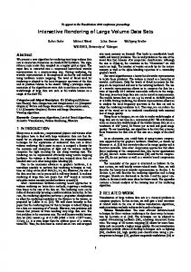
Figure 1: Volume renderings of the Torso data set with over one million tetrahedra using view-aligned sampling. From left to right: full quality (100% LOD) rendering at 2.0 fps, 25% LOD at 5.3 fps, 10% LOD at 10.0 fps, and 5% LOD at 16.1 fps.
A BSTRACT We describe a new dynamic level-of-detail (LOD) technique that allows real-time rendering of large tetrahedral meshes. Unlike approaches that require hierarchies of tetrahedra, our approach uses a subset of the faces that compose the mesh. No connectivity is used for these faces so our technique eliminates the need for topological information and hierarchical data structures. By operating on a simple set of triangular faces, our algorithm allows a robust and straightforward graphics hardware (GPU) implementation. Because the subset of faces processed can be constrained to arbitrary size, interactive rendering is possible for a wide range of data sets and hardware configurations. CR Categories: I.3.5 [Computer Graphics]: Computational Geometry and Object Modeling— Surface and object representations, geometric algorithms; I.3.3 [Computer Graphics]: Picture/Image Generation Keywords: interactive volume rendering, multiresolution meshes, level-of-detail, tetrahedral meshes 1
I NTRODUCTION
Unstructured meshes are common in scientific computing. Direct volume rendering for these meshes follows two main approaches: ray casting and cell projection in visibility order. These approaches are typically too slow for interactivity when full resolution meshes are rendered. Thus, level-of-detail (LOD) techniques are an attractive way to trade off rendering quality for rendering speed. However, unlike for rectilinear volumes, it is not well studied how LOD
techniques should be applied to unstructured meshes. There have been two basic approaches to LOD for unstructured meshes, typically for the special case of tetrahedral meshes. The first has been employed in ray casting where the scalar field along the ray is sparsely sampled to improve speed. The second is to simplify the mesh into a hierarchy of new meshes, each with fewer tetrahedra than its parent mesh. The ray tracing approach has the advantage of simplicity and robustness, and the mesh simplification approach has the advantage that it can be easily used in a graphics hardware (GPU) implementation. This paper describes a technique that attempts to capture the simplicity of the ray sampling method while still allowing a natural GPU implementation. This is accomplished by sparsely sampling the faces between tetrahedra in the mesh without creating an explicit hierarchy of LODs. The GPU is used to perform ray integration between these sparsely sampled faces without the need for connectivity information. This avoids the complexity of the mesh simplification methods, but still allows a GPU implementation, which makes a fast and robust LOD rendering system possible (Figure 1). Our main contributions are: 1. We propose a new sample-based LOD framework for rendering unstructured grids that can be implemented by simply using a subset of mesh faces. 2. We examine several strategies for deciding which faces to draw, and discuss their relative merits. 3. We provide an efficient implementation of our techniques, and show that they can be applied to generate high-quality renderings of large unstructured grids. The remainder of this paper is layed out as follows. We summarize related work in Section 2. In Section 3 we lay the framework for sample-based simplification for LOD. A description of our sampling strategies is described in Section 4. In Section 5 we present
our implementation details. Our experimental results are shown in Section 6, and in Section 7 we discuss the different trade-offs with our approach. Finally, in Section 8 we provide our conclusions and future work. 2
R ELATED W ORK
Volume rendering unstructured grids has been a topic of much research, and major advances have been made in performing this rendering efficiently (e.g., [1, 25, 31, 34, 37, 40]). Because the size of the unstructured grids continues to increase faster than our visualization techniques can handle them, other research has focused on approximately rendering unstructured grids to maintain interactivity [4, 13, 20, 28]. The two main techniques have been to use LOD representations of the data [2, 3, 16, 33], or to sparsely sample viewing rays. The approximate rendering was first done by sampling sparsely along viewing rays [8]. This idea can work for unstructured meshes as well, provided there is a mechanism for skipping cells entirely (e.g., [30]). Alternatively, a multiresolution approach is commonly used to increase the rendering speed of triangle meshes [23]. They often work by dynamically selecting a set of triangles to approximate the surfaces to within some error bound, or to meet some target frame rate [15, 22]. For structured grids, computing and dynamically rendering multiple LODs is relatively straightforward. This can be accomplished by using hardware-accelerated techniques that involve slicing the volume with view-aligned texture hierarchies [19, 38]. Because the data is structured, the view-aligned slices can be computed quickly and compositing can be accomplished by blending the fragments into the framebuffer in the order in which they are generated. For unstructured meshes the problem is not as well studied. One way to speed up the rendering is to statically simplify the mesh in a preprocessing step to a mesh small enough for the volume renderer to handle [2, 3, 16]. However, this approach only provides a static approximation of the original mesh and does not allow for dynamic changes to the level of detail. This way, the user can not easily refine features of interest, or dynamically adapt the LOD to the capabilities of the hardware being used. Dynamic LOD approaches are preferable, and have shown to be useful by Museth and Lombeyda [28] even if the pictures generated are of a more limited type than full-blown volume renderings. To our knowledge, the only two approaches that describe dynamic LOD volume rendering for unstructured meshes are the recent works by Cignoni et al. [4] and Leven et al. [20]. Cignoni et al. [4] propose a technique based on creating a progressive hierarchy of tetrahedra that is stored in a multitriangulation data structure [14] that is dynamically updated to achieve interactive results. Their algorithm is quite clever (and involved), as an efficient implementation requires the use of compression of the topology and hierarchical information to be practical. Leven et al. [20] convert the unstructured grid into a hierarchy of regular grids that are stored in an octree, and can be rendered using LOD techniques for regular grids. Their experiments show that the resulting LOD hierarchy is over two orders of magnitude larger than the original data. Both of these techniques require some form of hierarchical data structures, fairly involved preprocessing, and relatively complex implementations. Many methods have simplified triangle meshes into smaller sets of textured polygons (e.g., [9, 24]). Another approach is to use compression schemes to minimize the bandwidth of the geometry [11]. Of these, our method is most similar in spirit to the randomized Zbuffer [36] or the work by Deussen et al. [10], where a subset of all the geometry is drawn. Our algorithm is also related to the sampling work of Danskin and Hanrahan [8]. Some of our sampling strategies are reminiscent of Monte Carlo rendering (e.g., [5, 7]).
3
A S AMPLE -BASED LOD F RAMEWORK
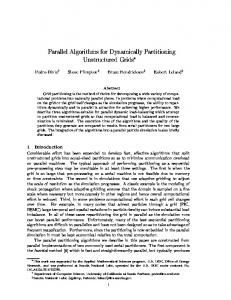
In scientific computing, it is common to represent a scalar function f : D ⊆ R3 → R as sampled data by defining it over a domain D, which is represented by a tetrahedral mesh. For visualization purposes, we define the function f as linear inside each tetrahedron of the mesh. In this case, the function is completely defined by assigning values at each vertex vi (x, y, z), and is piecewise-linear over the whole domain. The domain D becomes a 3D simplicial complex defined by a collection of simplices ci . It is important to distinguish the domain D from the scalar field f . The purpose of visualization techniques, such as isosurface generation [21] and direct volume rendering [25] are to study intrinsic properties of the scalar field f . The time and space complexity of these techniques are heavily dependent on the size (or number of simplices) and shape of the domain D. For large data sets, it is not possible to achieve interactive visualization without using an approximation. In these cases, it is often useful to generate a reduced-resolution scalar field f¯ : D¯ ⊆ R3 → R, such that: • the new scalar field f¯ approximates f in some natural way, i.e., | f¯ − f | ≤ ε; • the new domain D¯ is smaller than D. LOD techniques attempt to compute multiple approximations f¯i from f at decreasing resolutions for interactive visualization. Recently, techniques have been proposed that hierarchically simplify the tetrahedral mesh by using edge collapses (see [4]). These techniques work similarly to triangle based simplification and use connectivity information to incrementally cull simplices ci from the domain D, i.e., when a 1-simplex is collapsed, several 2- and 3simplices become degenerate and can be removed from the mesh. Most techniques order the collapses using some type of error cri¯ reaches the deterion, stopping when the size of the domain |D| sired LOD. f¯ computed in this way for LOD can be considered as a domain-based simplification of f because the domain D is being resampled with fewer vertices. An alternative approach for computing f¯ is sample-based simplification. If we consider a ray r that leaves the viewpoint and passes through screen-space pixel (x, y) then enters the scalar field f , a continuous function g(t) is formed for r where g(t) = f (r0 + trd ). In the domain D, represented by a tetrahedral mesh, this function g(t) is piecewise-linear and defined by the set of points P = {pi x,y }. An approximation g(t) ¯ can be created by using a subset P¯ of P. In other words, by removing some of the samples that define g(t), we obtain an approximating function g(t). ¯ This subsampling can occur on the tetrahedral mesh using any of the 2- or 3-simplices. The key difference between domain- and sample-based simplification is that they approximate the domain D in different ways with respect to the volume integral. If you consider the ray r passing through a medium represented by D, the volume rendering integral is computed at each 2-simplex intersection within D (see Max [26]). Domain-based simplification approximates the domain D, then computes an exact volume integral over the approximate geometry. Sample-based simplification uses the original geometry to represent D, then computes an approximate volume integral over the original geometry. Figure 2 shows a 2D example of the function g(t) and approximate functions g¯1 (t) and g¯2 (t) using these two approaches as the ray r passes through D. It is important to emphasize that sample-based simplification provides different, though not necessarily better, results than domain-based simplification. The advantage of this approach is the simplicity of the simplification method and data structures necessary to perform dynamic LOD. Because we want f¯ to be a good approximation of f , when using sample-based simplification it is necessary to ensure that each
Figure 2: Classification of LOD simplification techniques in 2D represented by a mesh and the function occurring at a ray r through the mesh. Undefined areas of the volume are expressed as dashed lines. (a) The original mesh showing the function g(t) that ray r passes through. (b) The mesh after sample-based simplification where the function approximation g¯1 (t) is computed by removing samples from the original function g(t). (c) The mesh after domain-based simplification, where the approximating function g¯2 (t) is computed by resampling the original domain.
ray r passing through f¯ encounters at least two samples to avoid holes in the resulting image. Furthermore, by removing geometry without constraint in a nonconvex mesh, we could possibly be computing the volume integral over undefined regions outside of D. This problem can easily be resolved by always guaranteeing that the boundary B of f is always sampled (see Figure 2). This problem is similar to importance sampling where the integral can be approximated using probabilistic sampling or Monte Carlo techniques [7, 32]. However, this is a much more difficult problem when considering the entire space of functions that occur because of the infinite number of viewpoints. Therefore, sampling strategies that attempt to optimize the coverage of the functions from all viewpoints become necessary. 3.1
Face Subsampling
The sample-based simplification strategy described above operates on the existing geometric representation of the mesh. In principle, the sampling could be done on any of the simplices that compose the mesh. We choose to sample by the faces (triangles) that make up the tetrahedra. This is due to the flexibility and speed of the sampling that it allows. If we consider the topology of the mesh as a collection of triangles (2-simplices) embedded in R3 , f¯i can be computed at each LOD i by selectively sampling a portion of the faces. Thus, by removing one triangle, we are effectively removing one sample of the function g(t) that represents f along the ray r. The advantage of this technique is that it provides a natural representation for traversing the different LODs. Given a set of unique faces F in a tetrahedral mesh, boundary faces B and internal faces I can be extracted such that B ∪ I = F. Since B gives a minimum set of faces that bound the domain D of the mesh, B should remain constant. By adding and removing faces from I, we get an approximation of the mesh where B ∪ I ⊆ F. This leads to a simple formula for determining the number of faces in I that need to be selected in each pass: |I|
=
|I prev | × TargetTime , RenderTime
where TargetTime is the amount of time you would like each frame to take for interactive viewing, i.e., 0.1 seconds, and RenderTime is the time that the previous frame required to render. This allows the system to adapt the LOD to the current view and render complexity.
It also allows an easy return to the full quality mesh by selecting all the internal faces to be drawn with the boundary faces. 4
S AMPLING S TRATEGIES
To minimize visual error the faces should be chosen while accounting for both transfer function and viewpoint. However, to maximize visual smoothness when the viewpoint or the transfer function change, the faces should be based only on mesh geometry and scalar field values. This conflict between accuracy and ability to change viewpoint and transfer function easily indicates that the best sampling strategy will depend on user goals and properties of the data. For this reason we provide a variety of sampling strategies. We described the steps that are required to achieve interactive rates given an internal face list. However, the heuristics that are incorporated to assign importance to the faces are just as important. We describe four methods that operate on different properties of the mesh: topology sampling, view-aligned sampling, field sampling, and area sampling strategies (Figure 4). The first two strategies are deterministic. The second two strategies are randomized, each rewarding different data attributes. We also implemented a naive randomized algorithm that selected a uniformly random subset of faces, but these results were poor for the same reason unstratified sampling is poor when sampling pixels: clumping and holes [27]. 4.1
Topology Sampling
The first sampling method that we employ is based on the topology of the initial tetrahedral mesh. This approach assigns layers to some of the faces in an attempt to select faces that are connected, resulting in an image that looks more continuous. Similar work has been done for determining a sequence of nonconvex hulls on a point set [12]. This approach requires a preprocessing step in which we extract the boundary, remove the tetrahedra on the boundary, and repeat until all the tetrahedra have been peeled from the mesh. A new layer value is assigned to the faces on the boundary at each step in the algorithm and separated into the boundary face list (layer zero) and the internal face list (all other faces). The preprocessing layer extraction algorithm is given in Figure 3. This algorithm assigns layers to some of the faces, but not all of them. In practice, it uses enough of the faces for a good image. However, when all of the layer faces cannot be drawn because they exceed the limit of internal faces allowed for interactive rendering,
EXTRACT LAYERS CurrentLayer ← 0 for each tetrahedron t Peeled[t] ← false while there exists t such that Peeled[t] = false for each face f f ← External Set s = 0/ for each tetrahedron t such that Peeled[t] = false for each face f in t if f is already in s f ← Internal else insert f into s for each face f such that f = External f ← CurrentLayer for each tetrahedron t such that f and t share a vertex Peeled[t] = true CurrentLayer ← CurrentLayer + 1
Figure 3: Pseudocode for extracting the topology layers of a tetrahedral mesh.
a subset of the layers are rendered. This is done by picking an even distribution of the layers throughout the mesh until the target internal face count is reached. 4.2
View-Aligned Sampling
The second sampling strategy that we use is view-aligned sampling. The intuition to this approach is that the faces perpendicular to the viewing direction are the most visible ones. Therefore, by selecting the internal faces that are more closely aligned to the current view, we can optimize the screen-space coverage. A simple approach would be to perform a dot product between each internal face normal and the viewing direction to order the faces in the internal face list. However, this approach is costly because it requires processing on every face independent of the LOD. Instead, we use a simple technique based on the work of Kumar et al. [18] and Zhang and Hoff [41] for back-face culling. In a preprocessing step, the faces are clustered by their normals. The clusters are computed by fitting a bounding box to a unit sphere and subdividing the faces of the box into regions. This grid is then projected onto the sphere, and the internal faces are clustered based on their normal’s location in the distribution. Clearly, this is not a uniform distribution, but in practice it produces good results. We used a 4 × 4 grid for each of the faces of the bounding box, which results in 96 normal clusters. This allows us to detect view-aligned faces based on their cluster instead of individually, which significantly increases the performance of the algorithm. 4.3
Figure 4: A 2D example of sampling strategies for choosing internal faces. (a) A topology sampling which calculates layers by peeling boundary tetrahedra. (b) A view-aligned sampling that selects the faces most relevant to the current viewpoint. (c) A field sampling which uses stratified sampling on a histogram of the scalar values. (d) An area sampling which selects the faces by size.
Field Sampling
Our third approach for sampling internal faces is based on the field values of the tetrahedral mesh. In most cases this is represented as a scalar at each vertex in the mesh. This technique assigns importance to a face based on the average scalar value at its vertices. In a preprocessing step, a histogram is built using the normalized scalar values, which shows the distribution of the field. Using an approach similar to stratified sampling in Monte Carlo integration, we divide this histogram into evenly spaced intervals (we use 128), then randomly pick the same number of faces from each interval to be rendered. Unlike Monte Carlo integration, which provides the underlying theory for randomly sampling to approximate a function, we are randomly sampling over the entire space of functions. The internal face list is filled with these random samples, so that no extra computation is required for each viewpoint or change in LOD.
A similar technique can be applied to the field using the transfer function. Intuitively, samples should be selected based on opacity instead of scalar value. A histogram is built using the opacity of the scalar values from the transfer function and sampled randomly as previously described. The tradeoff of this method is that it requires resampling with every transfer function update. Due to this constraint, we sample without the transfer function in our experiments. 4.4
Area Sampling
Our fourth strategy recognizes that if the removal of a triangle causes an error of a certain magnitude at a given pixel, then the total error magnitude for all pixels is proportional to the area of that triangle. Thus we could prioritize based on area. An easy way to do this while preserving the possibility of choosing small faces is to prioritize based on Ai ∗ ξi where Ai is the area in R3 of the ith face and ξi is a uniform random number. This randomizes the selected triangles, but still favors the larger ones being drawn. As with field sampling, this list does not need to be rebuilt for new viewpoints or number of faces to be drawn. 5
I MPLEMENTATION
The algorithm for dynamic LOD builds on the Hardware-Assisted Visibility Sorting (HAVS) volume rendering system proposed by Callahan et al. [1]. Figure 5 shows an overview of how the sampling interacts with the volume renderer. In a preprocessing step, the boundary faces are separated from the internal faces and each are put in a list. Each internal face contains a neighboring face with the same vertices and scalar values. To avoid the redundancy of computing a zero-length interval, these duplicate faces are removed. The internal face list is reordered from most important to least important based on one of sampling strategies previously described. This allows us to dynamically adjust the number of faces that are being drawn by passing the first |I| faces to the volume renderer along with the boundary faces. For full quality images, which are shown when the user is not interactively viewing the mesh, the entire internal face list is used.
Figure 5: Overview of the dynamic LOD algorithm. (a) The LOD algorithm samples the faces and dynamically adjusts the number of faces to be drawn based on the previous frame rate. (b) The HAVS volume rendering algorithm sorts the faces on the CPU and GPU and composites them into a final image.
Once the proper subset of faces has been selected, the HAVS algorithm prepares the faces for rasterization by sorting them by their centroids. This provides only a partial order of the faces in object-space since the mesh may contain faces of varying size or even visibility cycles. Upon rasterization, the fragments undergo an image-space sort via the k-buffer, which has been implemented using fragment shaders. The k-buffer keeps a fixed number of fragments (k) in each pixel of the framebuffer. As a new fragment is rasterized, it is compared with the other entries in the k-buffer, the two entries closest to the viewpoint (for front-to-back) are used to find the color and opacity for the fragment using a lookup table which contains the preintegrated volume integral. The color and opacity are composited in the framebuffer, and the remaining fragments are written back to the k-buffer (see [1] for more detail). For dynamic LOD, we are interested in the time that each frame requires to render so we can adjust accordingly. Therefore, we track the render time at each pass and use it to adjust the number of internal faces that are sent to the rasterizer in the next step. This is very important when you are interacting with the system. Since the bottleneck of the volume renderer is rasterization, by zooming in or out, the frame rate can increase or decrease depending on the size of the faces being drawn. Dynamically adjusting the LOD ensures that frame rates remain constant. We use 10 frames per second as a target frame rate for a good balance in interactivity and quality. As described above, HAVS requires a preintegrated lookup table to composite the image-space fragments. This table is represented as a 3D texture that looks up a front fragment scalar, a back fragment scalar, and the distance between the fragments. Unfortunately, we remove samples, thereby introducing intervals that are larger than the maximum edge length from which the lookup table is built. In a software implementation, this problem could be resolved by repeatedly compositing the fragment until the gap has been filled similar to Danskin and Hanrahan [8]. However, this repetition does not map to current hardware. To solve this issue we create a separate lookup table, which is preintegrated to handle rays that span the entire bounding box of the mesh. This secondary lookup table is used during the dynamic LOD where the quality difference is not as noticeable and is replaced by the original table when rendering full quality images. Using a logarithmic scale of the distance to build the lookup table would further improve the image quality during LOD rendering [17]. 6
R ESULTS
Our experiments were run on a PC with a 3.2 GHz Pentium 4 processor and 2,048 MB RAM. The code was written in C++ with OpenGL and uses an ATI Radeon X800 Pro graphics processor with 256 MB RAM. The Spx2, Torso, and Fighter data sets were used to measure performance and to compare the sampling strategies.
Figure 6: Plot of the render time for the Spx2 (blue), Torso (red), and Fighter (black) at different LODs using field sampling. Approximately 3% LOD is the boundary only and 100% LOD is a full quality image.
An important consideration with LOD techniques is the preprocessing time to create the data structures necessary for interactive rendering. Table 1 shows the three data sets with their sizes and the time required to preprocess the original mesh into static LODs using the different sampling strategies. The results show that all strategies can be preprocessed quickly, which is important in realworld use, where data may be regenerated with different parameters repetitively. Rendering a tetrahedral mesh using sample-based LOD dynamically is based on the fundamental assumption that the render time decreases proportionally to the number and size of the faces that are sampled. The performance of our volume renderering system is based on the number of fragments that are processed at each frame. This roughly corresponds to the number of faces that are rasterized. Figure 6 shows the performance of the volume rendering system as the number of sampled faces increases. The almost linear scale factor provides a good estimate of the number of faces that would be required to render a data set at a specific frame rate. It is important to note that sampling by area or by view decreases the number of faces that can be rasterized interactively because the screen-space area of the faces is generally larger, resulting in more fragments. For example, 10% LOD using area sampling will take longer to render than 10% LOD using field sampling. Another important aspect of sample-based LOD is choosing a sampling strategy that gives the best approximation of your original mesh. To measure the effectiveness of our sampling strategies, we generated images of each data set at 14 fixed viewpoints using all the sampling strategies and compared the results with full quality results from the same viewpoints. Unfortunately there are not yet accepted methods for accurately predicting the magnitude of the difference between two images (as opposed to whether images are perceived as identical where good methods do exist [29]). In the absence of such an ideal method, we compare images with root mean square error (RMSE). These measurements should only be Data Set Spx2 Torso Fighter
Tetrahedra 828 K 1,084 K 1,403 K
Topology 17.8 87.2 75.6
View 5.3 11.6 15.3
Field 4.5 10.5 13.9
Area 13.9 11.2 15.3
Table 1: Preprocessing time in seconds of the different sampling strategies for dynamic LOD. The time represents all operations on the mesh after it has been loaded from file before the first rendering pass occurs.
Figure 7: Direct comparison of the different sampling strategies with a full quality rendering of the Spx2 data set (828 K tetrahedra). Full quality is shown at 2.5 fps and LOD methods are shown at 10 fps (3% LOD for area sampling and 10% LOD on all other strategies).
Figure 8: Error measurements of the different sampling strategies for 14 fixed viewpoints on the Spx2, Torso, and Fighter data sets. Root mean squared error is used to show the difference between the full quality rendering and the LOD rendering at 10 fps.
used as a subjective tool for where the images differ as opposed to any quality ranking for LOD strategies. Figure 8 shows the three data sets at the different viewpoints and the error measured between each LOD sampling strategy and a full quality image. Notice that no sampling strategy is superior in all cases, but they all provide a good approximation. To provide a more qualitative analysis of the sampling strategies, we also show images of the different techniques on the same data set. Figure 7 shows a direct comparison of the strategies with a full quality rendering. 7
D ISCUSSION
Our algorithm is designed to meet a speed goal while maintaining what visual quality is possible and in this sense it is oriented toward time-critical systems such as TetSplat [28]. Unlike TetSplat, our method aims to do direct volume rendering with transfer functions rather than surface rendering with castaways. Our method also has the advantage that it requires very little additional storage beyond the original mesh. Approaches that sample the unstructured mesh on a regular grid [20] increase the original data size substantially and require extensive preprocessing. Our method is an alternative to rendering explicit hierarchical meshes [4]. While explicit hierarchies are elegant and provide excellent visual quality, they require more preprocessing than our technique, are difficult to implement, and they do not easily allow for continuous LOD. The main advantage of explicit hierarchies over our technique is that they can provide smoother imagery that may be a better visual match to an exact rendering. However, our subjective impression is that our approximate rendering is more than accurate enough for interaction with volume data, and what objective visual accuracy is needed for visualization tasks is an interesting and open question (see Figure 9). A key characteristic of our algorithm is that it operates on mesh
faces rather than mesh cells. This results in fewer primitives than methods that render cells by breaking them into polygons (e.g., [31, 39]), which improves overall bandwidth of the rendering algorithm. For example, given n tetrahedra, projected tetrahedra algorithms render 3.4n triangles, while HAVS renders only 2n. Furthermore, the set of all possible mesh faces to be rendered do not change with viewpoint, just the order and number of the face indices. Thus, we can leave the geometry in memory on the GPU for better efficiency. Another advantage of our system is that it works with perspective or parallel projections with no additional computation. Most importantly, a face-based method allows faces to be dropped without major errors in opacity because the HAVS method is aware of adjacent faces visible through a pixel, whereas dropping cells in cellbased methods leads to undesirable accumulation of empty space which causes the volume to gradually grow more and more transparent as cells are dropped. So for cells, unlike faces, some explicit simplification hierarchy is required. Our four sampling strategies each select a subset on the set of mesh cell faces. View-aligned sampling attempts to choose a subset based on view directions, and this emphasizes the quality of individual frames at the expense of coherence between frames. The other three methods choose a subset independent of viewpoint and thus do not have flickering artifacts. Topology sampling builds a set of shells for its subsets and produces images without obvious holes, but does so at the expense of correlated regions in the image. Field sampling uses a randomized algorithm over binned densities to choose a subset. This is a robust strategy but because it completely ignores connectivity it has obvious discontinuities in intensity. In practice, sampling by scalar value and sampling by opacity using the transfer function produce simlar results. Area sampling rewards larger faces and also achieves robustness via randomization. While rewarding larger faces does seem to lower visual error, it also lowers the number of triangles that are rasterized because of the larger fill requirements. Overall, each method has its merits and we expect the best choice to be data and application dependent.
Figure 9: The Fighter data set (1.4 million tetrahedra) shown in multiple views at full quality on top (1.3 fps), 15% LOD (4.5 fps) in the middle, and at 5% LOD (10.0 fps) on the bottom. The LOD visualizations use area-based sampling.
We tried to keep our implementation both simple and robust while minimizing preprocessing costs. The idea behind trying to minimize preprocessing costs was to lower the effort to load new data into the system. Our design choices cause certain limitations. One of the most significant being that the lowest LOD the current system can support is limited by the size of the boundary of the mesh (which appears to hover around 3% for several of the data sets we tried). We note that there are ways around this issue, e.g., we can simplify the boundary using traditional surface simplification as done in [35]. We also note that we have not fully optimized our system. In particular, we are not using view-frustum culling, which certainly can lead to substantial speedups in closeup views. 8
C ONCLUSIONS AND F UTURE W ORK
Our technique is based on an alternative solution to the subsampling problem needed for LOD rendering. Instead of using a domainbased approach which maintains different versions of a valid unstructured mesh in a hierarchical data structure our sample-based approach is based on rendering with a subset of the mesh faces. These faces correspond to the intersection points of the underlying unstructured grid with rays going through the center of the screenspace pixels. In effect, our technique directly subsamples the vol-
ume rendering integral as it is computed. We have shown this to be effective in interactive visualization of unstructured meshes too large for approximation-free rendering. This effectiveness is largely because our technique is particularly well-suited to GPU implementation. In the future it would be useful to do user-studies to determine what types of visual error are detrimental to success in visualization tasks. Such studies could guide which sampling strategies are best. It would also be interesting to see whether our face sampling method would be useful in ray tracing volume renderers as the data reduction might benefit them as well. Another area of future work is to extend our system to handle data sets too large for main memory through the use of compression techniques similar to [11] or out-of-core storage of the data set as in [6]. We would also like to extend our algorithm to handle hexahedron which should involve either using quadrilaterals directly or splitting them into triangles for efficiency. As a final direction for future work, we are interested in using our algorithm to visualize dynamic data. ACKNOWLEDGMENTS The authors thank Carlos Scheidegger for insightful discussions, John Schreiner for help with the paper, and Mark Segal from ATI
for donated hardware. The authors acknowledge Bruno Notrosso (Electricite de France) for the Spx data set, Neely and Batina (NASA) for the fighter data set, and the Scientific Computing and Imaging Institute (Utah) for the Torso. Steven P. Callahan is supported by the Department of Energy (DOE) under the VIEWS program. The work of Jo˜ao L. D. Comba is supported by a CNPq grant 478445/2004-0. Cl´audio T. Silva is partially supported by the DOE under the VIEWS program and the MICS office, the National Science Foundation (grants CCF-0401498, EIA-0323604, OISE0405402, and IIS-0513692), and a University of Utah Seed Grant. Peter Shirley is partially supported by National Science Foundation under grant CCF-0306151.
R EFERENCES [1] S. P. Callahan, M. Ikits, J. L. Comba, and C. T. Silva. HardwareAssisted Visibility Ordering for Unstructured Volume Rendering. IEEE Transactions on Visualization and Computer Graphics, 11(3):285–295, 2005. [2] Y.-J. Chiang and X. Lu. Progressive simplification of tetrahedral meshes preserving all isosurface topologies. Computer Graphics Forum, 22(3):493–504, 2003. [3] P. Chopra and J. Meyer. TetFusion: an algorithm for rapid tetrahedral mesh simplification. In Proceedings of IEEE Visualization 2002, pages 133–140, 2002. [4] P. Cignoni, L. D. Floriani, P. Magillo, E. Puppo, and R. Scopigno. Selective Refinement Queries for Volume Visualization of Unstructured Tetrahedral Meshes. IEEE Transactions on Visualization and Computer Graphics, 10(1):29–45, 2004. [5] R. L. Cook. Stochastic Sampling in Computer Graphics. ACM Transactions on Graphics, 5(1):51–72, 1986. [6] W. T. Corrˆea, J. T. Klosowski, and C. T. Silva. iWalk: Interactive OutOf-Core Rendering of Large Models. Technical Report TR-653-02, Princeton University, 2002. [7] B. Csebfalvi. Interactive Transfer Function Control for Monte Carlo Volume Rendering. In Proceedings of IEEE Symposium on Volume Visualization and Graphics, pages 33–38, 2004. [8] J. Danskin and P. Hanrahan. Fast algorithms for volume ray tracing. In Proceedings of the 1992 Workshop on Volume Visualization, pages 91–98, 1992. [9] X. D´ecoret, F. Durand, F. Sillion, and J. Dorsey. Billboard Clouds for Extreme Model Simplification. In Proceedings of SIGGRAPH, 2003. [10] O. Deussen, C. Colditz, M. Stamminger, and G. Drettakis. Interactive visualization of complex plant ecosystems. In Proceedings of IEEE Visualization, pages 219–226, Washington, DC, USA, 2002. IEEE Computer Society. [11] O. Devillers and P.-M. Gandoin. Geometric Compression for Interactive Transmission. In Proceedings of IEEE Visualization 2000, pages 319–326, Los Alamitos, CA, USA, 2000. IEEE Computer Society Press. [12] M. J. Fadili, M. Melkemi, and A. ElMoataz. Non-convex onionpeeling using a shape hull algorithm. Pattern Recognition Letters, 25(14):1577–1585, 2004. [13] R. C. Farias, J. S. B. Mitchell, C. T. Silva, and B. Wylie. Time-Critical Rendering of Irregular Grids. In Proceedings of the 13th Brazilian Symposium on Computer Graphics and Image Processing, pages 243– 250, 2000. [14] L. D. Floriani, P. Magillo, and E. Puppo. Efficient Implementation of Multi-Triangulations. In IEEE Visualization ’98, pages 43–50, 1998. [15] T. A. Funkhouser and C. H. S´equin. Adaptive Display Algorithm for Interactive Frame Rates During Visualization of Complex Virtual Environments. In Proceedings of ACM SIGGRAPH 1993, pages 247– 254, 1993. [16] M. Garland and Y. Zhou. Quadric-Based Simplification in Any Dimension. ACM Transactions on Graphics, 24(2), Apr. 2005. [17] M. Kraus, W. Qiao, and D. S. Ebert. Projected Tetrahedra without Rendering Artifacts. In Proceedings of IEEE Visualization, pages 27– 34, 2004.
[18] S. Kumar, D. Manocha, W. Garrett, and M. Lin. Hierarchical backface computation. In Proceedings of the Eurographics Workshop on Rendering techniques ’96, pages 235–ff., 1996. [19] E. LaMar, B. Hamann, and K. Joy. Multiresolution Techniques for Interative Texture-based Volume Visualization. In Proceedings of IEEE Visualization 1999, 1999. [20] J. Leven, J. Corso, J. D. Cohen, and S. Kumar. Interactive Visualization of Unstructured Grids Using Hierarchical 3D Textures. In Proceedings of IEEE Symposium on Volume Visualization and Graphics, pages 37–44, 2002. [21] W. E. Lorensen and H. E. Cline. Marching Cubes: A High Resolution 3D Surface Construction Algorithm. In Proceedings of ACM SIGGRAPH 1987, pages 163–169, 1987. [22] D. Luebke and C. Erikson. View-Dependent Simplification of Arbitrary Polygonal Environments. In Proceedings of SIGGRAPH 1997, pages 199–208, 1997. [23] D. Luebke, M. Reddy, J. Cohen, A. Varshney, B. Watson, and R. Huebner. Level of Detail for 3D Graphics. Morgan-Kaufmann Publishers, 2002. [24] P. W. C. Maciel and P. Shirley. Visual Navigation of Large Environments Using Textured Clusters. In Symposium on Interactive 3D Graphics, pages 95–102, 1995. [25] N. Max, P. Hanrahan, and R. Crawfis. Area and volume coherence for efficient visualization of 3D scalar functions. ACM SIGGRAPH Comput. Graph., 24(5):27–33, 1990. [26] N. L. Max. Optical Models for Direct Volume Rendering. IEEE Transactions on Visualization and Computer Graphics, 1(2):99–108, 1995. [27] D. P. Mitchell. Consequences of Stratified Sampling in Graphics. In Proceedings of SIGGRAPH, pages 277–280, 1996. [28] K. Museth and S. Lombeyda. TetSplat: Real-time Rendering and Volume Clipping of Large Unstructured Tetrahedral Meshes. In Proceedings of IEEE Visualization 2004, pages 433–440, 2004. [29] K. Myszkowski. The Visible Differences Predictor: Applications to Global Illumination Problems. In Eurographics Rendering Workshop, pages 223–236, 1998. [30] S. Parker, M. Parker, Y. Livnat, P.-P. Sloan, C. Hansen, and P. Shirley. Interactive Ray Tracing for Volume Visualization. IEEE Transactions on Visualization and Computer Graphics, 5(3):238–250, 1999. [31] P. Shirley and A. Tuchman. A Polygonal Approximation to Direct Scalar Volume Rendering. Proc. San Diego Workshop on Volume Visualization, 24(5):63–70, Nov. 1990. [32] P. S. Shirley. Time Complexity of Monte Carlo Radiosity. In Eurographics ’91, pages 459–465, 1991. [33] O. G. Staadt and M. H. Gross. Progressive Tetrahedralizations. In Proceedings of IEEE Visualization 1998, pages 397–402, 1998. [34] C. Stein, B. Becker, and N. Max. Sorting and Hardware Assisted Rendering for Volume Visualization. In Proc. IEEE Symposium on Volume Visualization, pages 83–89, Oct. 1994. [35] D. Uesu, L. Bavoil, S. Fleishman, J. Shepherd, and C. T. Silva. Simplification of Unstructured Tetrahedral Meshes by Point-Sampling. In Proceedings of IEEE/EG International Workshop on Volume Graphics 2005, pages 157–165, 2005. [36] M. Wand, M. Fischer, I. Peter, F. M. auf der Heide, and W. Straßer. The Randomized Z-Buffer Algorithm: Interactive Rendering of Highly Complex Scenes. In Proceedings of ACM SIGGRAPH 2001, pages 361–370, 2001. [37] M. Weiler, M. Kraus, M. Merz, and T. Ertl. Hardware-Based Ray Casting for Tetrahedral Meshes. In Proc. IEEE Visualization, pages 333–340, Oct. 2003. [38] M. Weiler, R. Westermann, C. Hansen, K. Zimmerman, and T. Ertl. Level-Of-Detail Volume Rendering view 3D Textures. In Proceedings of IEEE Volume Visualization 2000, 2000. [39] J. Wilhelms and A. V. Gelder. A coherent projection approach for direct volume rendering. In Proceedings of SIGGRAPH, pages 275– 284, 1991. [40] P. L. Williams. Visibility-Ordering Meshed Polyhedra. ACM Transactions on Graphics, 11(2):103–126, 1992. [41] H. Zhang and I. Kenneth E. Hoff. Fast backface culling using normal masks. In Proceedings of the 1997 Symposium on Interactive 3D Graphics, pages 103–106, 1997.