Interactive Simulation of Power Electronics Circuits – a SIMPLORER© Approach Ž.Jakopović, Z.Benčić and F.Kolonić Faculty of Electrical Engineering and Computing Unska 3, HR-10000 Zagreb, Croatia Phone: (+385 1) 61 29 804 Fax: (+385 1) 61 29 705 E-mail:
[email protected],
[email protected],
[email protected]
Abstract – Basic benefits of simulation and requirements for appropriate power electronic system modeling and simulation tools are reported. As a candidate for optimal power electronic system simulator, SIMPLORER© software package is suggested. It is mixed-mode mixed-language circuit oriented simulator. Together with its add-ons, SIMPLORER© can solve the most complicated problems from the field of power electronics systems. Two simple educational projects are described, clearly showing good properties of described software for modeling and simulation of power electronics systems. As a very special property, possibility of interactive simulation using keyboard intervention during simulation is emphasized.
I. INTRODUCTION Today there is an evident need for modeling and simulation of power electronics circuits in the field of design, research and development as well as in the education area. Power electronics circuits, with their application objects (motor drives, actuators, etc.), are very complex objects, requiring multidisciplinary approach in their analysis. Systems to be analyzed are electrical circuits with switching elements, control system blocks, control algorithms and logical expressions. Modeling and simulation of such a complex system is not a simple task. Choosing the right modeling and simulation tool is crucial for efficiency of design process. What are basic benefits of simulation in the design process of power electronics systems? Simulation is surely an efficient way of learning how power electronics circuit and its control works. It is therefore well suited for research and development as well as education field. With the help of simulation, possible problems can be discovered in early phase of design process, resulting with adequate financial benefits. It is easy to provide an optimization procedure for optimal circuit and control parameters, by means of appropriate modeling and simulation. Simulation is ideal for nondestructive testing of circuits and control algorithms. Responses to system faults and abnormal working conditions can be thoroughly analyzed with practically no material cost and with great safety. As opposed to real power electronic systems, it is possible to simplify certain parts of circuit in order to focus on specific part of the circuit. Simulation is possible on several complexity levels depending on what answers on circuit behavior are expected.
II. REQUIREMENTS ON MODELING AND SIMULATION TOOLS
As mentioned in introduction, it is not easy to choose the right modeling and simulation tool for power electronics systems. Basic requirements on power electronics modeling and simulation tools are following. User-friendly interface enables fast and accurate input and output of data, as well as processing and display of results. Multilevel modeling capability is required from a good simulation program, to allow various approaches to system modeling, e.g. differential equations, state variables, transfer functions, logical expressions etc. Accurate switch models and robust switching operations are necessary for efficient simulation of power electronics systems, consisting primary of switching elements (diodes, transistors…). Numerical integration algorithm, as a basis of each simulator, has to take care of fast switching times, what can lead to numerical instability problems. Execution time of simulation should be in acceptable limits. Power electronic systems have a huge span between the time constants of its parts. Numerical integration algorithm of the simulator should take care of the proper integration step to reach good accuracy and acceptable execution time. Initial conditions in power electronics systems are important for faster reaching the steady state of operation. Good simulation program should enable the user to set, save and load initial and final conditions of power electronics system. Basically there are 2 broad categories of simulation programs appropriate for power electronics systems. First are Equation solvers (MATRIXx, MATLAB/ SIMULINK…) and second are Circuit simulators (SPICE, EMTP, SIMPLORER…). Equation solvers are more universal, but not so appropriate for detailed analysis of electrical circuits. Circuit simulators are better suited for electrical circuit analysis, with lower capabilities in description of control systems and algorithms. Modern circuit simulators are approaching in their capabilities to Equation solvers. There are many circuit simulators on the market today, differing in some fundamental respects as used numerical integration method for solving differential equations, treatment of non-linearities, integration time step control, search of break points, treatment of switch models and possible incorporation of controllers and external models for multilevel simulation. After more years of experience in R&D and educational field, the SIMPLORER simulation package is found to
fulfill in the great extent all the requirements for power electronics system simulator.
III. SIMPLORER© - POWER ELECTRONICS SYSTEM SIMULATOR
A. Basic features SIMPLORER is mixed-mode mixed-language circuit oriented simulator. It consists of 3 different simulators, ideally coupled and synchronized. Network simulator is circuit simulator dedicated for modeling and simulation of electrical circuits, with libraries specially prepared and optimized for power electronics systems. Block-diagram simulator is similar to standard equation simulators (e.g. SIMULINK) and is dedicated for description and simulation of control laws and hybrid systems, which could be described by means of transfer functions or differential equations. Block-diagram simulator works in continuous and discrete domain. Third part of SIMPLORER is state-graph simulator for description of event-driven systems and control laws. State-graph simulator is efficient tool for modeling even very complex control laws. Formulae/Functions/Characteristics Module of SIMPLORER additionally enhances the functionality of SIMPLORER. It provides the possibility for specification of time-dependent functions or non-linear elements and for generating signals from and for different system parameters of the components. The definition of userdefined modules is also possible in the form of macromodules or C-code. Definition of model to be simulated can be provided in textual, or more convenient graphical form. SIMPLORER has its own graphical input tool. This graphical input schematic tool is very convenient way of defining the problem to be solved. Many different libraries are on the disposition to the user. Electrical circuit library contains all kinds of linear and non-linear, independent or dependent, passive elements (resistors, capacitors and inductors) and voltage and current sources. There are also basic models of semiconductor switches and electrical machines. Function module library contains basic time functions (sine, square wave, etc.), characteristic functions (exp, poly, etc.), machine characteristics for machine models and SPICE characteristics for semiconductor switch models. Block diagram module library contains necessary basic blocks for description of dynamic systems, such as discrete or continuous transfer functions, PID blocks, limiters etc. State graph module library contains basic elements of state-graph theory, net elements and states. There are more basic libraries on disposal (magnetic circuits, digital elements etc.) as well as additional optional libraries for nonlinear and linear transmission elements and basic power electronics circuits with appropriate control laws. Simulation parameters (integration method, time step, errors, limits of simulation, etc.) can be defined and changed before the simulation, enabling accurate control of simulation process. Two methods of numerical integration can be chosen, trapezoidal or Euler’s. Display of results is on-line, during simulation, as opposed to PSPICE. Data analysis program DAY is integral part of
SIMPLORER simulator, serving for display and analysis of simulated data. B. Advanced features Besides basic SIMPLORER simulators and DAY tool for display and analysis of data, there are many other useful tools enhancing the power of SIMPLORER. This tools are Model Agent, Experiment Tool, Analytical Frequency Response Tool, Mag Expert, C-Interface, SimulinkInterface, IEEE-Interface, Fuzzy-Interface. Model Agent is tool for handling many available models and macros distributed in several standard and optional libraries. It can edit existing models and save new developed models. Experiment Tool with optimization serves for finding the optimum set of parameters in certain system with the help of several task types, as trend analysis, Monte Carlo analysis, worst case analysis, successive approximation, genetic algorithm, frequency analysis and multisimulation. Mag Expert is preprocessor for determination of model parameters of nonlinear magnetic models. C-Interface enables the user to design and implement own (nonlinear) functions or algorithms programmed using C/C++. Simulink-Interface makes a connection to well-known simulator of Equation solver type, MATLAB/SIMULINK. Now it is possible to provide parallel simulation on both simulators, SIMPLORER and SIMULINK. Power electronics system with its control can be separated in two parts and then simulated with optimal simulator.
IV. INTERACTIVE SIMULATION On-line display of results during the simulation enables the user to see immediately the flow of simulation. If something is wrong with model, simulation can be stopped and model can be corrected. But SIMPLORER offers even more. It is interactive simulator, enabling the user to intervene into the model or simulation parameters during the simulation. Each system variable can be reached easily during the simulation by proper textual addressing. TYPE_KEY_ KEY :=
INCREASE_R1 SET := wert"R1":=wert"R1"*1.1
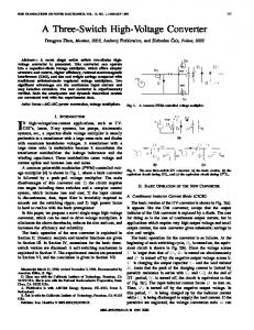
Fig.1. An example of state graph modeling with keyboard intervention
This interesting and useful feature is explained by following examples. Voltage on resistor R1 can be called with U”R1”. Value of resistor R1 can be read or changed with WERT”R1”. Also in the modules of Block simulator (e.g. continuous transfer function G(z)) each parameter of a module can be read or changed. P01”Bl_name” means first parameter of block named Bl_name. In this way an adaptation of controller parameters can be done during the
simulation. The parameters of time functions can be reached in the same way, enabling the change of amplitude, frequency or other characteristic value of time function. The use of state-graph simulator is especially appropriate for intervention into simulation during the simulation. As really special feature of SIMPLORER, possibility of keyboard intervention can be emphasized. Fig.1 illustrates this feature. Two states are defined, input and output, with transfer condition between them, called net element. For each state an action can be defined, which will be processed if the state is active. There are 12 possible actions, where following are the most interesting. Action SET: calculates the value of variable only once at the moment of activation of the according state. This is very important for changing the parameters by keyboard intervention. On example shown on Fig.1. pressing the key C changes the value of resistor R1 by 10%. Action DEL: sets a delay (a sort of monostable). The variable is set to false at the moment of activation and set to true after the delay time. Action KEY: sets a mark in the state by pressing a certain key. There are really many possibilities for using state graph modeling. It can be used for on-line adaptation of system parameters during the simulation, for changing the structure of the system. Even simulation parameters can be changed during the simulation, as minimum and maximum integration steps (HMIN, HMAX), time of simulation, integration algorithm etc. State graph modeling can be used also for creating the control laws for power switches. As shown in the example, current mode PWM for switches in H-bridge can be easily defined with only a few states and net elements.
V. CHARACTERISTIC EXAMPLES Many examples of sophisticated use of SIMPLORER in different areas of power electronics can be found, but we have chosen 2 basic examples clearly showing SIMPLORER’s application in the education. First one is single-phase bridge line converter with different types of load, and second one is H-bridge inverter with transistor type switches and current mode PWM. In both examples intervention from computer keyboard changes the structure or parameters of simulated system during the simulation. Project with single-phase bridge line converter is first example dedicated for explaining the fundamentals of line converters theory, Fig.2. Keyboard is used for change between inductive load, pure resistive load, ideal current source load, free wheeling diode. Also firing angle α, counter EMF E, commutation inductances Lk can be changed via keyboard. Some results of such an interactive simulation can be seen also on Fig.3, where load voltage
and current are influenced by changes from keyboard. The result of change, caused by key pressing, is immediately seen on display. Additional analysis of results, e.g. FFT of load voltage or line current, can be performed after simulation using the DAY tool. Project with H-bridge inverter with inductive load and hysteresis control is second example, Fig.3. Different complexity levels of power switch models can be used. From ideal switch models to SPICE based models or special macros based on behavioral modeling. For educational purposes, if only voltage-current relations on the load are of interest, not the details of switching on power switches, it is advisable to use simple model of transistor with appropriate VI nonlinear characteristic. Width of hysteresis D, which can be changed by pressing the keys L or S, defines the switching frequency of inverter and harmonic spectra of load current. The influence of hysteresis width on load current waveform can be seen on upper right part of Fig.3. Interesting waveforms showing the behavior of control signals for switches, load voltage and load current are shown on lower right part of Fig.3. Very interesting is the way of modulation realization. Initial value assignment (ICA) and Permanent assignment (VA) expressions are defining basic parameters of current reference signal. Power switches TR1-TR4 are switched on or off according to the law defined by state graph modeling. State graph modeling is also used for keyboard activated change of hysteresis width, Fig.3.
VI. CONCLUSION SIMPLORER is powerful modeling and simulation tool dedicated for power electronics systems. It can solve the specific problems that appear in that field. Because of 3 different modeling languages incorporated in SIMPLORER, different types of systems can be easily described, electrical circuits, block diagrams and event driven discrete systems. From the described examples, the feature of interactive simulation through keyboard intervention into simulation can be seen. This is original feature of SIMPLORER, appropriate for educational purposes, as well as in field of research and development.
REFERENCES [1] B.K.Bose, Power Electronics and Variable Frequency Drives, IEEE Press, 1997. [2]
N.Mohan, T.Undeland and W.Robbins, Power Electronics – Converters, Applications and Design, 2nd Edn., Wiley, New York, 1995.
[3]
SIMPLORER© 4.0, Reference Manual, SIMEC GmbH, Germany, 1998.
R_d
EXP1 L_k
B2C
D_FD L_d
S_Ld
+ V
ET_V
t
VM_d
SINUS
E_EMF
K2
S_FD
K1
US_CS
P
E
S_CS
ICA :
ICA1 I_CS
NE1
KEY := D
NE3
SET := C_FD:=
KEY := I
KEY := d
SET := C_FD:=0
KEY := i
SET := ALFA:=ALFA+
SET := C_Ld:=0
SET := C_CS:=1 NE11
KEY := E
NE10
SET := ALFA:=ALFA
KEY := k
SET := wert"E_EMF":=wert"E_EMF"+50 NE12
SET := wert"L_k":=wert"L_
KEY := e
SET := wert"E_EMF":=wert"E_EMF"-50
NE15
SET := wert"R_d":=wert"R_d"*2 KEY := L NE14
KEY := r
KEY := c
SET := wert"L_k":=wert"L_
KEY := K
NE13
KEY := R
SET := C_CS:=0 SET := wert"I_CS":=i"R_ NE6
NE9
NE8
KEY := a
KEY := C
NE4
NE7
KEY := A
NE5
SET := C_Ld:=1
NE2
R_CS
SET := wert"L_d":=wert"L_d"*2 NE16
KEY := l
SET := wert"R_d":=wert"R_d"/2
SET := wert"L_d":=wert"L_d"/2
Fig.2. SIMPLORER Worksheet with project Single-phase bridge line converter
ICA :
VA1 :
A := 30 D := 0.05 frequ := 50 OMEGA := 2*PI*frequ
I_SET := A*SIN(OMEGA*T) I_UPR := I_SET+D*A I_LWR := I_SET-D*A
key pressed key pressed
SET := TSV1:=1 SET := TSV2:=0 SET := TSV3:=0 SET := TSV4:=1
SMALLER
SMALLER1
KEY :=
SET := D:=0.05
i"R_load">=I_UPR
ON14 LARGER1
LARGER
PSI"L_load" U"L_load"
0.346k
ON23 0.173k
KEY :=
SET := D:=0.1
i"R_load"


![[READ] Power Electronics: Circuits Book - Google Sites](https://m.moam.info/img/260x300/read-power-electronics-circuits-book-google-sites_64777e98097c474e708bc3d3.jpg)

![[Full] Power Electronics: Circuits eBook - Google Sites](https://m.moam.info/img/260x300/full-power-electronics-circuits-ebook-google-sites_64780730097c4786708c5dac.jpg)


![[DOWNLOAD] Power Electronics: Circuits Book - Google Sites](https://m.moam.info/img/260x300/download-power-electronics-circuits-book-google-si_64774c9c097c474c228bdf85.jpg)


![[EBOOK] Download Power Electronics: Circuits ... - Google Sites](https://m.moam.info/img/260x300/ebook-download-power-electronics-circuits-google-s_6478b0a1097c474e708d1709.jpg)