perZ hardware, and the NV GL occlusion query OpenGL exten- sion [Scott et al. 1998; Bartz et al. 1999; Greene 2001; Klosowski and Silva 2001; Hillesland et al.
Interactive View-Dependent Rendering with Conservative Occlusion Culling in Complex Environments Sung-Eui Yoon Brian Salomon Dinesh Manocha University of North Carolina at Chapel Hill {sungeui,salomon,dm}@cs.unc.edu http://gamma.cs.unc.edu/VDR Abstract
This paper presents a novel algorithm combining view-dependent rendering and conservative occlusion culling for interactive display of complex environments. A vertex hierarchy of the entire scene is decomposed into a cluster hierarchy through a novel clustering and partitioning algorithm. The cluster hierarchy is then used for view-frustum and occlusion culling. Using hardware accelerated occlusion queries and frame-to-frame coherence, a potentially visible set of clusters is computed. An active vertex front and face list is computed from the visible clusters and rendered using vertex arrays. The integrated algorithm has been implemented on a Pentium IV PC with a NVIDIA GeForce 4 graphics card and applied in two complex environments composed of millions of triangles. The resulting system can render these environments at interactive rates with little loss in image quality and minimal popping artifacts. CR Categories: I.3.5 [Computer Graphics]: Computational Geometry and Object Modeling - surface and object representations Keywords: Interactive Display, View-Dependent Rendering, Occlusion Culling, Level of Detail, Multiresolution Hierarchies
1
Introduction
Complex models composed of millions of primitives have become increasingly common in computer graphics and scientific visualization. One of the major challenges is rendering these datasets at interactive rates on commodity hardware. Different rendering acceleration algorithms based on model simplification and visibility culling have been developed that reduce the number of primitives sent through the graphics pipeline. Model simplification algorithms reduce the number of primitives by replacing highly tessellated objects in the scene by coarser representations. These algorithms generate different levels-of-detail (LODs). At a high level, they can be classified into static and dynamic algorithms. The static LOD generation algorithms precompute discrete approximations and switch between them at runtime based on the viewer’s position. These algorithms have very little runtime overhead and can efficiently use vertex arrays and display lists. However, switching between different LODs can lead to popping artifacts at runtime. Dynamic simplification (or view-dependent rendering (VDR)) algorithms represent an environment using a hierarchy of simplification operations (e.g. vertex hierarchy). The rendering algorithm traverses the hierarchy in an incremental manner and computes a front that satisfies the error bound based on the viewing parameters. VDR algorithms offer several benefits over static LOD-based systems. First, the level of mesh refinement can vary over the surface of an object to meet the error bound in the screen space. This
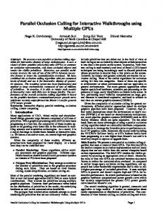
Figure 1: Coal-Fired Power Plant: This environment consists of over 12 million triangles and 1200 objects. Our view-dependent rendering with occlusion culling algorithm can render this environment at 10 − 20 frames per second with very little loss in image quality on a Pentium IV PC with a NVIDIA GeForce 4 graphics card. alleviates the popping artifacts that occur when an LOD changes. Furthermore, view information not available during a preprocess can be used to preserve effects such as silhouette edges and specular highlights. Despite these advantages, the application of VDR algorithms to complex environments has been limited. Problems arise from traversing and refining an active vertex front, or cut, across the vertex hierarchy. In practice, refining a front for a model composed of hundreds of objects or millions of polygons can take hundreds of milliseconds or more per frame. Moreover, rendering the triangles in the front at interactive rates may not be possible, especially on models with high depth complexity. Conservative occlusion culling algorithms cull away portions of the scene that are not visible from the current view location using a potentially visible set (PVS). Most of these algorithms represent the scene using a spatial partition or bounding volume hierarchy and perform object-space or image-space culling tests to compute the PVS at runtime. Given the complexity of large environments, integrated approaches that combine model simplification and occlusion culling are needed for interactive display. However, current techniques merely combine static LODs with conservative occlusion culling or VDR with approximate occlusion. Each of these techniques can generate popping artifacts at runtime. It is important to develop an integrated representation that can be used both for VDR and conservative occlusion culling. Main Contributions: We present a novel algorithm that combines VDR with conservative occlusion culling. We precompute a vertex hierarchy of simplification operations for a large environment and a cluster hierarchy on top of the vertex hierarchy. We discuss a number of criteria to design an optimal cluster hierarchy and present techniques that automatically compute the hierarchy for large environments. We associate a bounding volume with each cluster so
that the cluster hierarchy implicitly functions as a bounding volume hierarchy and is used to perform occlusion culling using hardware accelerated occlusion queries. The runtime algorithm maintains a list of active clusters. This list is traversed as the mesh is refined within visible clusters to meet the error bound. The primitives within the refined clusters are rendered using vertex arrays. The cluster-based occlusion culling algorithm limits the size of the active vertex front. As a result, the algorithm can refine and render the front at interactive rates. The overall algorithm has been implemented on a Pentium IV PC with a NVIDIA GeForce 4 graphics card. It has been applied to two complex environments: a power plant model with more than 1200 objects and 12.2 million triangles, and an isosurface model composed of 2.4 million polygons and a single object. The algorithm can render these datasets at 10 − 20 frames a second with very little loss in image quality and minimal popping artifacts. New Results: Some of the novel aspects of our work include: • An integrated scene representation for simplification and visibility computations based on a vertex hierarchy and a cluster hierarchy. • An automatic cluster generation algorithm that takes into account several criteria important for occlusion culling. • The first integrated algorithm for VDR and conservative occlusion culling that runs on commodity hardware, uses vertex arrays and is applicable to large and complex environments. Organization: The rest of the paper is organized as follows: We give a short survey of previous work on VDR and occlusion culling in Section 2. In Section 3 we give a brief overview of our approach as well as the underlying representation. Section 4 describes the cluster hierarchy generation and partitioning algorithm. The runtime algorithm for view-dependent refinement and occlusion culling is detailed in Section 5. We describe our implementation and highlight its performance on two complex environments in Section 6. Finally, in Section 7 we highlight areas for future work.
2
Related Work
We give a brief overview of the previous work in view dependent rendering, occlusion culling, and integrated approaches.
2.1
View-Dependent Rendering
View-dependent rendering originated as an extension of the progressive mesh [Hoppe 1996]. A progressive mesh is built from an input mesh by a sequence of edge collapses used to form a coarse mesh. Vertex splits, the inverse of an edge collapse, are used to restore the original mesh from the coarse mesh. Xia and Varshney [1997] and Hoppe [1997] each reported that many edge collapses are independent and can be organized as hierarchies instead of linear sequences to allow refinement at runtime. This representation allows an application to take into account view-dependent effects such as silhouette preservation and lighting. Luebke and Erikson [1997] developed a similar approach using octree-based vertex clustering operations. El-Sana and Varshney [1999] extended these ideas by using a uniform error metric based on cubic interpolants, reducing the cost of mesh fold-over tests, and developing a Voronoibased method for creating “virtual edges”. Pajarola [2001] improved the update rate of runtime mesh selection by exploiting properties of the half-edge mesh representation. This approach is well suited to individual manifold objects. However, CAD/CAM models often contain disjoint objects and nonmanifold topology. El-Sana and Bachmat [2002] presented an alternate approach to increase the update rate of VDR by using a prioritization scheme. Several out-of-core VDR approaches have been proposed in the literature for handling large datasets [Decoro and Pajarola 2002; Lindstrom 2003].
2.2
Occlusion Culling
The problem of computing the visible set of primitives from a viewpoint has been extensively studied in computer graphics and related areas. A recent survey of occlusion culling algorithms is given in [Cohen-Or et al. 2003]. Occlusion culling algorithms may be classified as region or point-based, image or object space, and conservative or approximate.
Many occlusion culling algorithms have been designed for specialized environments, including architectural models based on cells and portals [Airey et al. 1990; Teller 1992; Luebke and Georges 1995] and urban datasets composed of large occluders [Coorg and Teller 1997; Hudson et al. 1997; Schaufler et al. 2000; Wonka et al. 2000; Wonka et al. 2001]. These approaches generally precompute a potentially visible set (PVS) for a region. However, these algorithms may not obtain significant culling on large environments composed of a number of small occluders. Object space algorithms make use of spatial partitioning or bounding volume hierarchies [Coorg and Teller 1997; Hudson et al. 1997]; however, performing “occluder fusion” on scenes composed of small occluders with object space methods is difficult. Image space algorithms including the hierarchical Z-buffer [Greene et al. 1993; Greene 2001] and hierarchical occlusion maps [Zhang et al. 1997] are generally more capable of capturing occluder fusion. The PLP algorithm [Klosowski and Silva 2000] uses an approximate occlusion culling approach that subdivides space into cells and assigns solidity values based on the triangles in each cell. This algorithm can provide guaranteed frame rate at the expense of nonconservative occlusion culling. However, it can lead to popping artifacts as objects can appear or disappear between successive frames. Klosowski and Silva [2001] augment PLP with an image based occlusion test to design a conservative culling algorithm. The iWalk system [Correa et al. 2002] uses the PLP algorithm along with out-of-core preprocessing to render large models on commodity hardware. A number of image-space visibility queries have been added by manufacturers to their graphics systems. These include the HP occlusion culling extensions, item buffer techniques, ATI’s HyperZ hardware, and the NV GL occlusion query OpenGL extension [Scott et al. 1998; Bartz et al. 1999; Greene 2001; Klosowski and Silva 2001; Hillesland et al. 2002; Meissner et al. 2002]. Our integrated algorithm also utilizes these occlusion queries to perform occlusion culling.
2.2.1
Clustering
Often the original objects of a model are not represented in an optimal manner for occlusion culling algorithms. These algorithms need to represent the scene using an object hierarchy. Therefore, they create an object hierarchy by partitioning and clustering the model, and at runtime classifying objects as occluders and potential occludees. One recent approach to partitioning and clustering is presented by Baxter et al. [2002] and used in the GigaWalk system. It decomposes a large environment into almost equal-sized objects that are used for static LOD computations. Sillion [1994] and Garland et al. [2001] presented hierarchical face clustering algorithms for radiosity and global illumination. These approaches are not directly applicable to generating a cluster hierarchy from a vertex hierarchy for view-dependent rendering and occlusion culling.
2.3
Integrated Approaches
Many algorithms have been proposed that combine model simplification and occlusion culling. The Berkeley Walkthrough system [Funkhouser et al. 1996] combines visibility computation based on cells and portals with static LODs for architectural models. The MMR system [Aliaga et al. 1999] precomputes static LODs of objects and used hierarchical occlusion maps at runtime for interactive display. The system assumes that the model is partitioned into rectangular cells. Other approaches combining precomputed static LODs and conservative occlusion culling have been proposed [Baxter et al. 2002; Govindaraju et al. 2003b]. These algorithms represent the environment as a scene graph, precompute HLODs (hierarchical levels-ofdetail) for intermediate nodes and use them for occlusion culling. However, switching between static LODs and HLODs can cause popping. Moreover, these algorithms use additional graphics processors to perform occlusion queries. El-Sana et al. [2001] combined view-dependent rendering with the PLP algorithm to perform approximate occlusion culling. The integrated algorithm uses the solidity values to guide simplification, producing fewer triangles in mesh regions that are deemed highly occluded. This approach has been applied to portions of the power plant model consisting of hundreds of thousands of triangles. However, the algorithm does not perform conservative occlusion culling.
3
Overview
In this section we introduce some of the terminology and concepts used in our algorithm and give a brief overview of our approach.
3.1
Preprocess
Most view-dependent rendering algorithms use a vertex hierarchy built from an original triangulated mesh. The interior nodes are generated by applying a simplification operation such as an edge collapse or vertex clustering to a set of vertices. The result of the operation is a new vertex that is the parent of the vertices to which the operator was applied. Successive simplification operations build a hierarchy that is either a single tree or a forest of trees. At runtime the mesh is refined to satisfy an error bound specified by the user. We use the edge collapse operator as the basis for our vertex hierarchies and allow virtual edges so that disjoint parts of the model can be merged. We store an error value corresponding to the local Hausdorff distance from the original mesh with each vertex. This value is used to refine the mesh at runtime by projecting it to screen space where the deviation can be measured in pixels, which is referred to as “pixels of error.” A mesh “fold-over” occurs when a face normal flips during a vertex split or edge collapse. Vertex splits can be applied in a different order at runtime than during the hierarchy generation. This means that even though no fold overs occur during hierarchy generation, they may occur at runtime [Hoppe 1997; Xia et al. 1997; El-Sana and Varshney 1999]. To detect this situation we use a neighborhood test. The face neighborhood is stored for each edge collapse and vertex split operation when creating the hierarchy. At runtime, an operation is considered fold-over safe only if its current neighborhood is identical to the stored neighborhood. The vertex hierarchy can be interpreted as a fine-grained bounding volume hierarchy. Vertices have bounding volumes enclosing all faces adjacent when the vertex is created during simplification. However, such a bounding volume hierarchy is not well suited for occlusion culling because each bounding volume is small and can occlude only a few primitives. Furthermore, the culling algorithm will have to perform a very high number of occlusion tests. To address this problem, we partition the vertex hierarchy into clusters and represent them as a cluster hierarchy. Each cluster contains a portion of the vertex hierarchy. All vertex relationships from the vertex hierarchy are preserved so that a vertex node may have a child or parent in another cluster. The relationships of the cluster hierarchy are based on those of the vertex hierarchy, so that at least one vertex in a parent cluster has a child vertex in a child cluster. We characterize clusters based on their error ratio and error range. The error ratio is defined as the ratio of the maximum error value associated with a vertex in the cluster to that of the minimum. The error range is simply the range of error values between the maximum and minimum error values in a cluster. The error ratio and range are used in hierarchy construction, as described in Section 4. We present a novel clustering algorithm that traverses the vertex hierarchy to create clusters that are used for occlusion culling.
3.2
Runtime Algorithm
In a standard VDR algorithm, the active vertex front (also referred to as the active vertex list) is composed of the vertices making up the current mesh representation. The front must be updated every frame by determining whether vertices on the front should be replaced with their parent to decrease the level of detail, or replaced by their children to increase the detail in a region [Hoppe 1997; Luebke and Erikson 1997; Xia et al. 1997]. Additionally, a list of active faces, the active face list is maintained. In our algorithm the front is divided among the clusters. The active front will only pass through a subset of the cluster hierarchy which is called the “active clusters.” These active clusters are traversed, and the active vertex front is refined within each active cluster. We do not refine active clusters that are occluded, leading to a dramatic improvement in the front update rate and decreased rendering workload while still conservatively meeting the error bound. Occlusion culling is performed by exploiting temporal coherence. During each frame, the set of clusters visible in the previous frame is used as an occluder set. These clusters are first refined by traversing their active fronts and then rendered to generate an occlusion representation. Next, the bounding volumes of clusters on the active front are tested for visibility. Only the visible clusters
are refined and rendered using vertex arrays. This visible set then becomes the occluder set for the subsequent frame.
4
Clustering and Partitioning
In this section we present the cluster hierarchy generation algorithm. We initially describe some desirable properties of clusters for occlusion culling and present an algorithm designed with these properties in mind. We also present techniques to partition the vertices and faces among the clusters.
4.1
Clustering
We highlight some criteria used to generate the clusters from a vertex hierarchy, before describing our clustering algorithm. We have chosen oriented bounding boxes (OBBs) as our bounding volume because they can provide a tighter fit than spheres or axis aligned bounding boxes [Gottschalk et al. 1996]. OBBs require more computation than simpler bounding volumes, but clustering is a preprocess that is performed once per environment. Initially we consider issues in generating clusters that are not directly descended from each other; that is, they come from different branches of the cluster hierarchy. Such clusters should have minimal overlap in their bounding volumes for two reasons. First, highly interpenetrating clusters are unlikely to occlude each other. Second, when rendering their bounding volumes, the required fillrate is higher when they overlap. However, a parent cluster’s bounding box should fully contain the bounding box of its children so that when it is deemed fully occluded, the subtree rooted at that cluster may be skipped. We also want to control the number of vertices and faces in a cluster so that we have uniformly sized occluders and occludees. For occlusion culling it is desirable to have only one active cluster in a region of the mesh. If clusters have low error ratios, it is likely that multiple clusters will have to be active in a mesh region. On the other hand, a cluster that has a high error ratio will contain vertices spanning many levels of the hierarchy in its mesh region. In this case, few of the vertices contained in a cluster will be active from any given viewpoint. Therefore, we must balance the error ratio of clusters. Also, the error range of a cluster should not overlap with its parent or children. Otherwise, it is likely that they will contain active vertices simultaneously. These properties for the clusters can be summarized as: 1. Minimal overlap of bounding boxes of clusters not directly descended from each other. 2. The bounding box of a cluster is fully contained within its parent bounding box. 3. Minimal or no overlap of error range between parent and children clusters. 4. The error ratio is not too small or too large for a cluster. 5. The vertex and face count within a cluster are neither very large nor very small.
4.2
Cluster Hierarchy Generation
Our clustering algorithm works directly on an input vertex hierarchy without utilizing a spatial subdivision such as an octree. We assume that the vertex hierarchy from which the cluster hierarchy is generated exhibits high spatial coherence and is constructed in a bottom-up manner using edge collapses or vertex merges. A cluster hierarchy can be generated by either using a bottomup or top-down approach. A benefit of the bottom-up approach is spatial localization, but we assume that the vertex hierarchy already has this property. The top-down approach enables us to minimize the overlap of cluster bounding boxes. For this reason, we have chosen the top-down approach. We descend the vertex hierarchy from the roots while creating clusters. An active vertex front is maintained and vertices on the front are added to clusters. When a vertex is added to a cluster, it is removed from the front and replaced with its children. We do not add a vertex to a cluster if it cannot be split in a fold-over safe manner. Thus, the construction of such a cluster will have to wait until dependent vertices are added to other clusters. For this reason, we use a cluster queue and place a cluster at the back of the queue when we attempt to add a vertex that is not fold-over safe. Then, the cluster at the front of queue is processed.
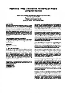
Figure 2: Construction of the Cluster Hierarchy : On the left is the input vertex hierarchy. The vertices are colored based on the cluster to which they are assigned. The nodes drawn with dotted lines represent the candidate vertices for the clusters, which reside in the vertex priority queue. The two clusters within dotted circles are still in the cluster queue, while the cluster inside the solid circle is finished processing. Each cluster in this cluster queue has an associated vertex priority queue sorted based on error values. A cluster’s vertex queue contains its candidate vertices on the active front. Initially, the cluster queue contains a single cluster. The vertex priority queue associated with this initial cluster contains the roots of the vertex hierarchy. Since candidate vertices within a cluster are processed in order of decreasing error value, it is never the case that a vertex split is dependent upon a split in its own vertex queue. While the cluster queue is not empty the following steps are performed: 1. Dequeue the cluster, C, at the front of the cluster queue. 2. Dequeue the vertex, v, with highest error from the vertex priority queue. 3. If splitting v is not fold-over safe, return it to the vertex priority queue, place C at the back of the cluster queue and go back to Step 1. 4. If adding v to C makes the error ratio of C too large or increases its vertex count beyond the target: (a) Create two children clusters Cl and Cr of C in the cluster queue. (b) Partition the vertex priority queue and assign the two resulting queues to Cl and Cr . (c) Go back to Step 1 without placing C in the back of the cluster queue; no more vertices will be added to this cluster. 5. Add v to C, update the number of vertices and the error ratio associated with C. 6. Replace v on the active vertex front by its children and enqueue the children in the vertex priority queue associated with C. Go back to Step 2. This clustering algorithm ensures the properties highlighted in Section 4.1. Section 4.3 will explain how Property 1 is enforced when a cluster is partitioned. Property 3 is maintained by our algorithm as the vertices are inserted into the clusters from the vertex priority queue in order of decreasing error, so that children clusters always contain vertices with less associated error than their parent cluster. Properties 4 and 5 cause the clusters to be split as the procedure traverses down the vertex hierarchy in Step 4. Property 2 is enforced in a second pass after clustering by a bottom-up traversal which computes each parent cluster’s bounding box by taking the union of its children. An example of a simple cluster hierarchy that is generated from vertex hierarchy is shown in Figure 2. Figure 3 shows the clusters on a bunny model at runtime.
4.3
Partitioning a Cluster
In Step 4(b) of the cluster generation algorithm, it is necessary to divide a cluster by splitting its vertex priority queue. The two resulting vertex priority queues form the initial vertex priority queues for the two children clusters. To partition a cluster we compute a splitting plane for the vertices in the queue using principal component analysis. The eigenvector
Figure 3: The clusters of the bunny model are shown in color. Clusters at 0 pixels of error are on the left and at 4 pixels of error are on the right. associated with the largest eigenvalue is initially used to define a splitting plane through the centroid of the vertices to maximally separate the geometry [Jolliffe 1986]. The vertices and associated faces are divided based on this splitting plane, and an oriented bounding box is computed that contains the faces of each cluster. Bounding boxes are oriented with the splitting plane. Some faces have a vertex in each of the newly created priority queues. As a result, their bounding boxes can overlap. This overlap can be very large when the cluster being split contains long, skinny triangles. Let V be the volume of the bounding box of the parent node and V0 and V1 be the volumes of the children bounding boxes. We use (V1 + V2 − V ) as a measure of the overlap of the children’s bounding boxes. If this value exceeds a threshold fraction of V then the overlap is too large. In this case, the eigenvector corresponding to the second largest eigenvalue is used to define a new splitting plane. If this split again fails the overlap test, the third eigenvector is used. If all three fail, then we enforce Property 1 by abandoning the split and keeping the parent cluster in the cluster queue and increase either the target vertex count or the error ratio.
4.4
Memory Localization
After assigning vertices to clusters, we store the vertices in their corresponding clusters along with their associated faces. Performing this memory localization is useful for rendering using vertex arrays and on demand loading of clusters at runtime. Also, memory accesses when processing a cluster are more likely to be localized. However, the vertices of a triangle can reside in different clusters. This is unavoidable in practice, no matter how the vertices are partitioned among different clusters. We deal with this situation by assigning each triangle to a single cluster containing at least one of its vertices. The cluster must store all three vertices of any triangle assigned to it, leading to some duplication of vertex data. Note, however, that only the data necessary to render such vertices is duplicated. The vertex hierarchy relationships are stored for each vertex only in the cluster to which they were assigned during cluster generation.
5
Interactive Display
In this section we present the runtime algorithm that uses the vertex and cluster hierarchy to update the active mesh for each frame and to perform occlusion culling. First, we present algorithms for model refinement followed by occlusion culling.
5.1
View-Dependent Model Refinement
In our algorithm the active vertex front or list and active face list, defined in Section 3.2, are divided among the clusters so that each cluster maintains its own portion of the active lists. Only clusters that contain vertices on the active front need to be considered during refining and rendering. These clusters are stored in an active cluster list. Figure 4 shows a cluster hierarchy, its active cluster list, and active vertex lists. Prior to rendering a cluster, its active face and vertex lists are updated to reflect viewpoint changes since the last frame. We traverse its active vertex list and use the aforementioned vertex error value to compute which vertices need to be split or collapsed. The error value is projected onto the screen and used as a bound on the deviation of the surface in screen pixels. Vertex splits are performed recursively on front vertices that do not satisfy the bound. For sibling pairs that meet the error bound, we recursively check whether their parent vertex also meets the error bound and if so, collapse the edge (or virtual edge) between the vertex pair.
Figure 4: The cluster hierarchy is used at runtime to perform occlusion culling. On the left, the active cluster list is drawn as a front across the cluster hierarchy. This list is composed of visible clusters and occluded clusters. Each cluster contains a portion of the vertex hierarchy as seen on the right. A subset of vertices in active clusters make up the current mesh. These are shaded on the right. Faces in the active face list adjacent to a vertex involved in either an edge collapse or vertex split are replaced with faces adjacent to the new vertex. When a vertex is to be split, we use the neighborhood test to determine whether the vertex split is fold-over safe. However, vertex splits must occur to satisfy the error bound. To allow a split, we force any of its neighboring vertices to split when they are not part of the stored neighborhood as in [Hoppe 1997].
5.2
Maintaining the Active Cluster List
A vertex that is split may have children that belong to a different cluster. The children vertices are activated in their containing clusters and these clusters are added to the active cluster list if they were not previously active. Similarly, during an edge collapse operation, the parent vertex is activated in its containing cluster and that cluster is added to the active cluster list. When the last vertex of a cluster is deactivated, the cluster is removed from the active cluster list.
5.3
Rendering Algorithm
Our rendering algorithm exploits frame-to-frame coherence in occlusion culling, by using the visible set of clusters from the previous frame as the occluder set for the current frame. The algorithm proceeds by rendering the occluder set to generate an occlusion representation in the depth-buffer. Then, it tests all the clusters in the active cluster list for occlusion. Meanwhile, the occluder set is updated for the next frame. An architecture of the runtime algorithm is shown in Figure 5. Different phases of the algorithm are numbered in the upper left of each box.
5.3.1
Occlusion Representation Generation
We use clusters that were visible in the previous frame for computing an occlusion representation. Before generating the representation, the active vertex list and active face list in each of these clusters are updated to meet the error bound. This refinement occurs as described in Section 5.1. This is Phase 1 of our algorithm. In Phase 2, the active faces are rendered and the resulting depth map is used as an occlusion representation.
5.3.2
Occlusion Tests
We traverse the active cluster list and cull clusters that are occluded or outside the view-frustum in Phase 3. The visibility of a cluster within the view frustum is computed by rendering its bounding box and then using a hardware occlusion query to determine whether any fragments passed the depth test. Depth writes are disabled during this operation to ensure that the bounding boxes are not used as occluders. Also, depth clamping is enabled so that we do not need to consider special case bounding boxes that are intersecting the near clip plane. The active vertex front may pass through a cluster and some of its descendant clusters. Since the bounding box of a cluster fully contains the bounding boxes of its children, once a cluster is found to be occluded we do not have to check its children. During this phase, all the clusters in the active cluster list are tested, including those in the occluder set. This test is necessary because the clusters that pass the visibility test are used as occluders for the subsequent frame. In this manner, clusters that become occluded are removed from the occluder set.
Figure 5: Runtime System Architecture: In each frame the clusters visible in the previous frame are used as an occluder set. In Phases 1 and 2, the occluder set is refined and then rendered to create a depth map in the z-buffer. Phase 3 tests bounding boxes of all the active clusters against this depth map using occlusion queries. The clusters passing the test are refined and rendered in Phases 4 and 5 and also used as occluders for the next frame.
5.3.3
Refining Visible Clusters
The previous phase allows us to determine which clusters are potentially visible. Before rendering the potentially visible clusters in Phase 5, their active face and vertex lists must be updated in Phase 4. While refining, additional clusters may be added to the active cluster list through vertex splits and edge collapses. These clusters are assumed to be visible in the current frame.
5.4
Conservative Occlusion Culling
The bounding box test conservatively determines whether the geometry within a cluster will be occluded, since a bounding box contains all the faces associated with a cluster. We also ensure conservativeness up to screen-space precision by refining the occluder set in Phase 1 before generating the depth map in Phase 2. To prevent refining and rendering the same cluster two times during a frame, the occluder set rendered in Phase 2 is also rendered into the color buffer. Then, when refining and rendering the visible clusters in Phases 4 and 5, we omit the clusters that were already refined and rendered in Phases 1 and 2. This optimization requires an extra step to ensure conservativeness. As explained in Section 5.1, the neighborhood vertices may be forced to split to satisfy the error bound. A problem arises when a vertex split in Phase 4 forces a vertex in a cluster already rendered in Phase 2 to split. We detect such cases and redraw the resulting faces, so that no visual artifacts remain in the final image. We rerender the affected faces prior to the split into the stencil buffer after setting the depth function to GL EQUAL. After the split, the correct faces are rendered and overwrite pixels where the stencil has been set. We have found that this occurs very rarely (on average less than one face per frame in our datasets).
5.5
Vertex Arrays
On current graphics processors display lists and vertex arrays are significantly faster than immediate mode rendering [Woo et al. 1997]. The changing nature of the visible primitives and dynamically generated LODs in a VDR system are not well suited for display lists. Thus, we use vertex arrays stored in the graphics processor unit (GPU) memory to accelerate the rendering. We use a memory manager when the size of the vertices in the active clusters is less than the amount of the memory allocated on the GPU (e.g. 100 MB). Using a least recently used replacement policy, we keep the vertices in GPU memory over successive frames. When the front size exceeds the memory requirement, we still use GPU memory, but do not attempt to keep clusters in this memory for more than one frame. In many rendering applications all or most of the vertices in a vertex array are used to render faces. But in our case only a fraction of the vertices for a cluster, the active vertices, are used for rendering. This increases the number of bytes per rendered vertex that are transferred to the GPU when using vertex arrays stored in GPU memory. To obtain maximum throughput, we use a minimum ratio of active vertices to total vertices, and any active cluster that does not meet this threshold is rendered in immediate mode.
Model Isosurface model Power Plant
Poly×106 2.4 12.2
Obj 1 1200
Cluster×103 1.3 20.1
Table 1: Details of our test environments. Poly is the polygon count. The Obj column lists the number of objects in the original dataset and the Cluster column lists number of clusters generated.
6
Implementation and Results
In this section we discuss some of the details of our implementation and highlight its performance on two complex environments.
6.1
Implementation
We have implemented our view-dependent rendering algorithm with conservative occlusion culling on a 2.8 GHz Pentium-IV PC, with 4 GB of RAM and a GeForce 4 Ti 4600 graphics card. It runs Linux 2.4 with the bigmem option enabled giving 3.0 GB user addressable memory. Using the NVIDIA OpenGL extension GL NV occlusion query, we are able to perform an average of approximately 100K occlusion queries per second on the bounding boxes. For higher performance, we allocate 100MB of the 128MB of RAM on the GPU to store the cluster vertices and bounding boxes. The memory allocated on the graphics card can hold about 3.5 million vertices.
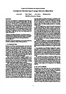
Figure 6: Isosurface model acquired from turbulence simulation. This environment consists of 2.4 million triangles and is rendered by our system at interactive rates.
6.2
6.3
Environments
Our algorithm has been applied to two complex environments, a coal fired power plant composed of more than 12 million polygons and 1200 objects (shown in Fig. 1) and an isosurface model consisting of 2.4 million polygons and a single object ( shown in Fig. 6). The details of these environments are shown in Table 1. We use GAPS [Erikson and Manocha 1999] to construct our vertex hierarchies because it handles non-manifold geometry and can also perform topological simplification. Because the GAPS algorithm requires large amounts of memory, we built hierarchies for portions of each environment separately and merged the results to compute a single vertex and cluster hierarchy. A target of 1000 vertices is used while generating the clusters. The maximum error value of any vertex in the cluster is twice that of the minimum; that is, the error ratio is 2. Our approach is designed for complex environments consisting of tens of millions of polygons. Partial loading can be very useful in such an environment. We decouple the vertex and face data from the edge collapse hierarchy stored in each cluster as described in Section 4.4. We do not load the face and vertex data for a cluster until it needs to be rendered. In this manner, clusters that never fall within the view-frustum or are always occluded will never be loaded when performing a walkthrough.
6.2.1
Preprocessing Time and Memory Requirements
Our cluster hierarchy generation algorithm can process about 1M vertices in 3.8 minutes. Almost 18% of that time is spent calculating the eigenvectors computed for principal component analysis when splitting clusters and determining OBBs. We optionally employ a step that attempts to tighten the OBBs by minimizing their volume while still enclosing the clusters. When this step is used, the time spent in cluster generation increases by ten times; the bounding box computation accounts for 90% of the time spent in the clustering step. We performed the minimization step during cluster generation for the power plant model and not for the isosurface model. Our current implementation is not optimized in terms of memory requirements. Each cluster uses 300 bytes to store the bounding box information and other data. Each vertex and face has a 4 byte pointer indicating its containing cluster along with the geometric data. On average, we use 272Mb for 1M vertices. This number is slightly higher in comparison with some earlier systems for viewdependent rendering. For example, Hoppe’s view-dependent simplification system [Hoppe 1997] reported 224Mb for 1M vertices. The difference partly exists because our implementation supports virtual edges and non-manifold topology, which means some relationships cannot be stored implicitly.
Optimizations
We use a number of optimizations to improve the performance of our algorithms.
6.3.1
Conservative Projected Error
When traversing the active vertex list of a cluster we use a conservative approximation of the distance from a vertex to the viewpoint. The minimum distance between a sphere surrounding a cluster and the viewpoint is computed. Then, the maximum surface deviation meeting the screen space error bound at this distance is calculated and all active vertices in the cluster are refined using this value. This approximation is conservative and requires only one comparison per vertex to determine whether it needs to be split or collapsed.
6.3.2
Multiple Occlusion Queries
The GL NV occlusion query extension supported on the GeForce 3 and all subsequent NVIDIA GPUs allows many queries to be performed simultaneously. To get the result of a query, all rasterization prior to issuing the query must be completed. Thus, we wait until we have rendered all the bounding boxes in the active cluster list before gathering query results from the GPU.
6.4
Results
We generated paths in each of our environments and used them to test the performance of our algorithm. These paths are shown in the accompanying video. We are able to render both these models at interactive rates (10 − 20 frames per second) on a single PC. We have also compared the performance of our system to VDR without occlusion culling. We accomplish this comparison by disabling occlusion culling in our system, which involves simply refining and rendering all the clusters in the active cluster list. Moreover, we do not use the conservative approximation of the error distance, since this optimization is possible because of clustering used for occlusion culling. We use view-frustum culling, vertex arrays, and GPU memory to accelerate the rendering of the scene in each case. Figure 8 illustrates the performance of the system on a complex path in the power plant and isosurface model. Notice that we are able to obtain a 3 − 5 times speedup with conservative occlusion culling. Table 2 shows the average frame rate, front size, and number of edge collapse and vertex split operations performed during the path. The main benefit of occlusion culling arises from the reduction in the size of the front (by a factor of one third to one half) as well as the number of rendered polygons. Tables 3 and 4 show a breakdown of the time spent on the major tasks (per frame) in our system. Due to occlusion culling, the resulting front size and the time spent in refining the front is considerably smaller and yields improved performance. Note that our improvement in refining is even more dramatic than the improvement in rendering due to the
Figure 7: Occlusion culling in the Power Plant. The left image shows a first person view. The middle image shows a third person view with the bounding boxes of visible clusters shown in pink and the view frustum in white. The right image is from the same third person view with the bounding boxes of occluded clusters in yellow. Model
Pixels of Error
VDR
FPS VDR+OC
Front Verts (K) VDR VDR+OC
Merge/Split VDR VDR+OC
VDR
Poly (K) VDR+OC
Visible
VF culled OC culled clusters in VDR+OC
Isosurface model 0.5 6.4 19.7 195 113 2356 1222 311 224 349 106 299 PP 3 2.62 12.3 297 126 1973 559 433 162 1166 390 1852 Table 2: Average frame rates and average number of split and merge operations obtained by different acceleration techniques over the sample path. This result is acquired at 512 × 512 image resolution. FPS = Frames Per Second, Poly = Polygon Count, PP = Power Plant model, VDR = View-dependent Rendering with view frustum culling, VF = View Frustum, OC = Occlusion Culling conservative distance computation. Figure 7 shows visible and invisible clusters in a given viewpoint on the power plant model.
6.5
Comparison with Earlier Approaches
To the best of our knowledge, none of the earlier algorithms can perform view-dependent rendering with conservative occlusion culling. The iWalk system [Correa et al. 2002] can also render the power plant model on a single PC with much smaller preprocessing and memory overhead than ours. However, it does not use LODs and performs approximate and non-conservative occlusion culling. The GigaWalk [Baxter et al. 2002] and occlusion-switch algorithms [Govindaraju et al. 2003b] use static LODs with occlusion culling. Although they can render the power plant model at interactive rates, they can produce popping due to switching between different LODs. Furthermore, they use more than one graphics processor. An integrated algorithm combining view-dependent rendering with PLP-based approximate occlusion culling is presented in [ElSana et al. 2001]. Finally, [El-Sana and Bachmat 2002] have presented a scheme for subdividing the vertex hierarchy at runtime to generate a coarser hierarchy. The cells of this hierarchy are split and merged to reflect the changes in the active front of vertices. These cells are prioritized by an estimate of the number of vertex splits and edge collapses required in each cell. Refinement occurs over a subset of the active cells in each frame, considering the priority as well as ensuring that all cells are eventually refined. Our algorithm follows the same theme of reducing the front size and therefore, subdivides the vertex hierarchy into clusters as a preprocess. As a result, our algorithm is applicable to very large environments and the resulting clusters are used for occlusion culling.
6.6
Limitations
Our occlusion culling algorithm assumes high temporal coherence between successive frames. If the camera position changes significantly from one frame to the next, the visible primitives from the previous frame may not be a good approximation of the occluder set for the current frame. As a result, the culling performance may suffer. Furthermore, if a scene has very little or no occlusion, the additional overhead of performing occlusion queries can lower the frame rate. Our algorithm performs culling at a cluster level and does not check the visibility of each triangle. As a result, its performance can vary based on how the clusters are generated and represented.
7
Conclusion and Future Work
We have presented a novel algorithm for integrating viewdependent rendering with conservative occlusion culling. Our algorithm performs clustering and partitioning to decompose a vertex hierarchy of the entire scene into a cluster hierarchy, which is used
Step VDR+OC VDR
Refining 17ms (34%) 136ms (81%)
Rendering 20ms (38%) 31ms (19%)
Culling 14ms (28%) −
Table 3: A breakdown of the frame time in isosurface model. Left values in each cell represent time spent in each step. Right values represent percentage of total frame time. The Refining column represents Phase 1 and 4, Rendering is Phase 2 and 5, and Culling is Phase 3. Step Refining Rendering Culling VDR+OC 23ms (28%) 27ms (33%) 31ms (39%) VDR 213ms (56%) 169ms (44%) − Table 4: A breakdown of the frame time in Power Plant. The columns Refining, Rendering, and Culling are explained in Table 3 for view-frustum and occlusion culling. At runtime, a potentially visible set of clusters is maintained using hardware accelerated occlusion queries, and this set is refined in each frame. The cluster hierarchy is also used to update the active vertex front that is traversed for view-dependent refinement. Our algorithm easily allows the use of vertex arrays to achieve high triangle throughput on modern graphics cards. We have observed 3 − 5 times improvement in frame rate over view-dependent rendering without occlusion culling on two complex environments. Many avenues for future work lie ahead. To apply our approach to even larger environments, we would like to develop an out-ofcore clustering and partitioning algorithm based on out-of-core simplification and generation of the vertex hierarchy. Our load on demand approach can be extended to create an out-of-core runtime system. Our clustering algorithm could be extended to consider view-dependent effects such as specular highlights and silhouettes that are important in environments with significant surface detail. In particular, it can be used for interactive shadow generation in complex environments [Govindaraju et al. 2003a]. We would like to explore other applications of the cluster hierarchy, including collision detection.
Acknowledgments Our work was supported in part by ARO Contract DAAD19-02-10390, NSF awards ACI 9876914 and ACR 0118743, ONR Contract N00014-01-1-0067 and Intel. The isosurface model is courtesy of the LLNL ASCI VIEWS Visualization project. The power plant environment is courtesy of an anonymous donor. We would like to thank Peter Lindstrom for processing the isosurface model, and the members of UNC Walkthrough group for their useful discussions and support.
(a) Isosurface model at 0.5 pixel of error
(b) Power plant model at 3 pixels of error
Figure 8: Frame rate comparison between VDR with and without occlusion culling. Image resolution is 512 × 512. We obtain a 3 − 5 times improvement in the frame rate when using occlusion culling.
References A IREY, J., ROHLF, J., AND B ROOKS , F. 1990. Towards image realism with interactive update rates in complex virtual building environments. In Symposium on Interactive 3D Graphics, 41–50. A LIAGA , D., C OHEN , J., W ILSON , A., Z HANG , H., E RIKSON , C., H OFF , K., H UDSON , T., S TUERZLINGER , W., BAKER , E., BASTOS , R., W HITTON , M., B ROOKS , F., AND M ANOCHA , D. 1999. Mmr: An integrated massive model rendering system using geometric and image-based acceleration. In Proc. of ACM Symposium on Interactive 3D Graphics. BARTZ , D., M EIBNER , M., AND H UTTNER , T. 1999. Opengl assisted occlusion culling for large polygonal models. Computer and Graphics 23, 3, 667–679.
H ILLESLAND , K., S ALOMON , B., L ASTRA , A., AND M ANOCHA , D. 2002. Fast and simple occlusion culling using hardware-based depth queries. Tech. Rep. TR02039, Department of Computer Science, University of North Carolina. H OPPE , H. 1996. Progressive meshes. In Proc. of ACM SIGGRAPH, 99–108. H OPPE , H. 1997. View dependent refinement of progressive meshes. In ACM SIGGRAPH Conference Proceedings, 189–198. H UDSON , T., M ANOCHA , D., C OHEN , J., L IN , M., H OFF , K., AND Z HANG , H. 1997. Accelerated occlusion culling using shadow frusta. In Proc. of ACM Symposium on Computational Geometry, 1–10. J OLLIFFE , I. 1986. Priciple component analysis. In Springer-Veriag.
BAXTER , B., S UD , A., G OVINDARAJU , N., AND M ANOCHA , D. 2002. Gigawalk: Interactive walkthrough of complex 3d environments. Proc. of Eurographics Workshop on Rendering.
K LOSOWSKI , J., AND S ILVA , C. 2000. The prioritized-layered projection algorithm for visible set estimation. IEEE Trans. on Visualization and Computer Graphics 6, 2, 108–123.
C OHEN -O R , D., C HRYSANTHOU , Y., S ILVA , C., AND D URAND , F. 2003. A survey of visibility for walkthrough applications. IEEE Transactions on Visualization and Computer Graphics. To Appear.
K LOSOWSKI , J., AND S ILVA , C. 2001. Efficient conservative visiblity culling using the prioritized-layered projection algorithm. IEEE Trans. on Visualization and Computer Graphics 7, 4, 365–379.
C OORG , S., AND T ELLER , S. 1997. Real-time occlusion culling for models with large occluders. In Proc. of ACM Symposium on Interactive 3D Graphics.
L INDSTROM , P. 2003. Out-of-core construction and visualization of multiresolution surfaces. In ACM Symposium on Interactive 3D Graphics.
C ORREA , W., K LOSOWSKI , J., AND S ILVA , C. 2002. iwalk: Interactive out-of-core rendering of large models. In Technical Report TR-653-02, Princeton University.
L UEBKE , D., AND E RIKSON , C. 1997. View-dependent simplification of arbitrary polygon environments. In Proc. of ACM SIGGRAPH.
D ECORO , C., AND PAJAROLA , R. 2002. Xfastmesh: View-dependent meshing from external memory. In IEEE Visualization.
L UEBKE , D., AND G EORGES , C. 1995. Portals and mirrors: Simple, fast evaluation of potentially visible sets. In ACM Interactive 3D Graphics Conference.
E L -S ANA , J., AND BACHMAT, E. 2002. Optimized view-dependent rendering for large polygonal dataset. IEEE Visualization, 77–84.
M EISSNER , M., BARTZ , D., H UTTNER , T., M ULLER , G., AND E INIGHAMMER , J. 2002. Generation of subdivision hierarchies for efficient occlusion culling of large polygonal models. Computer and Graphics.
E L -S ANA , J., AND VARSHNEY, A. 1999. Generalized view-dependent simplification. Computer Graphics Forum, C83–C94. E L -S ANA , J., S OKOLOVSKY, N., AND S ILVA , C. 2001. Integrating occlusion culling with view-dependent rendering. Proc. of IEEE Visualization. E RIKSON , C., AND M ANOCHA , D. 1999. Gaps: General and automatic polygon simplification. In Proc. of ACM Symposium on Interactive 3D Graphics. F UNKHOUSER , T., K HORRAMABADI , D., S EQUIN , C., AND T ELLER , S. 1996. The ucb system for interactive visualization of large architectural models. Presence 5, 1, 13–44. G ARLAND , M., W ILLMOTT, A., AND H ECKBERT, P. 2001. Hierarchical face clustering on polygonal surfaces. Tech. rep., Proc. of 2001 Symposium on Interactive 3D Graphics, Mar. G OTTSCHALK , S., L IN , M., AND M ANOCHA , D. 1996. OBB-Tree: A hierarchical structure for rapid interference detection. Proc. of ACM Siggraph’96, 171–180. G OVINDARAJU , N., L LOYD , B., YOON , S., S UD , A., AND M ANOCHA , D. 2003. Interactive shadow generation in complex environments. Proc. of ACM SIGGRAPH/ACM Trans. on Graphics. G OVINDARAJU , N., S UD , A., YOON , S., AND M ANOCHA , D. 2003. Interactive visibility culling in complex environments with occlusion-switches. Proc. of ACM Symposium on Interactive 3D Graphics. G REENE , N., K ASS , M., AND M ILLER , G. 1993. Hierarchical z-buffer visibility. In Proc. of ACM SIGGRAPH, 231–238. G REENE , N. 2001. Occlusion culling with optimized hierarchical z-buffering. In ACM SIGGRAPH COURSE NOTES ON VISIBILITY, # 30.
PAJAROLA , R. 2001. Fastmesh: Efficient view-dependent mesh. In Proc. of Pacific Graphics, 22–30. S CHAUFLER , G., D ORSEY, J., D ECORET, X., AND S ILLION , F. 2000. Conservative volumetric visibility with occluder fusion. Proc. of ACM SIGGRAPH, 229–238. S COTT, N., O LSEN , D., AND G ANNETT, E. 1998. An overview of the visualize fx graphics accelerator hardware. The Hewlett-Packard Journal, 28–34. S ILLION , F. 1994. Clustering and volume scattering for hierarchical radiosity calculations. In Fifth Eurographics Workshop on Rendering, 105–117. T ELLER , S. J. 1992. Visibility Computations in Densely Occluded Polyheral Environments. PhD thesis, CS Division, UC Berkeley. W ONKA , P., W IMMER , M., AND S CHMALSTIEG , D. 2000. Visibility preprocessing with occluder fusion for urban walkthroughs. In Rendering Techniques, 71–82. W ONKA , P., W IMMER , M., Eurographics.
AND
S ILLION , F. 2001. Instant visibility. In Proc. of
W OO , M., N EIDER , J., AND DAVIS , T. 1997. OpenGL Programming Guide, Second Edition. Addison Wesley. X IA , J., E L -S ANA , J., AND VARSHNEY, A. 1997. Adaptive real-time level-of-detailbased rendering for polygonal models. IEEE Transactions on Visualization and Computer Graphics 3, 2 (June), 171–183. Z HANG , H., M ANOCHA , D., H UDSON , T., AND H OFF , K. 1997. Visibility culling using hierarchical occlusion maps. Proc. of ACM SIGGRAPH.