February 2004
•
NREL/CP-560-35569
Interconnection Testing of Distributed Resources Preprint
B. Kroposki, T. Basso, and R. DeBlasio To be presented at the 2004 Power Engineering Society
General Meeting
Denver, Colorado
June 7, 2004
This work has been submitted to the IEEE for possible publication. Copyright may be transferred without notice, after which this version may no longer be accessible.
National Renewable Energy Laboratory 1617 Cole Boulevard Golden, Colorado 80401-3393 NREL is a U.S. Department of Energy Laboratory Operated by Midwest Research Institute • Battelle Contract No. DE-AC36-99-GO10337
NOTICE The submitted manuscript has been offered by an employee of the Midwest Research Institute (MRI), a contractor of the US Government under Contract No. DE-AC36-99GO10337. Accordingly, the US Government and MRI retain a nonexclusive royalty-free license to publish or reproduce the published form of this contribution, or allow others to do so, for US Government purposes. This report was prepared as an account of work sponsored by an agency of the United States government. Neither the United States government nor any agency thereof, nor any of their employees, makes any warranty, express or implied, or assumes any legal liability or responsibility for the accuracy, completeness, or usefulness of any information, apparatus, product, or process disclosed, or represents that its use would not infringe privately owned rights. Reference herein to any specific commercial product, process, or service by trade name, trademark, manufacturer, or otherwise does not necessarily constitute or imply its endorsement, recommendation, or favoring by the United States government or any agency thereof. The views and opinions of authors expressed herein do not necessarily state or reflect those of the United States government or any agency thereof. Available electronically at http://www.osti.gov/bridge
Available for a processing fee to U.S. Department of Energy and its contractors, in paper, from: U.S. Department of Energy Office of Scientific and Technical Information P.O. Box 62 Oak Ridge, TN 37831-0062 phone: 865.576.8401 fax: 865.576.5728 email:
[email protected] Available for sale to the public, in paper, from: U.S. Department of Commerce National Technical Information Service 5285 Port Royal Road Springfield, VA 22161 phone: 800.553.6847 fax: 703.605.6900 email:
[email protected] online ordering: http://www.ntis.gov/ordering.htm
Printed on paper containing at least 50% wastepaper, including 20% postconsumer waste
Interconnection Testing of Distributed Resources Benjamin Kroposki, Senior Member, IEEE, Thomas Basso, Member, IEEE, and Richard DeBlasio, Senior Member, IEEE quality, islanding, and test specifications and requirements for design, production, installation evaluation, commissioning, and periodic tests. These requirements are universally needed for the interconnection of DR—including synchronous generators, induction generators, and power inverters/converters—and will be sufficient for most installations. They are applicable to all DR technologies with aggregate capacity of 10 MVA or less at the point of common coupling that are interconnected with EPSs at typical primary or secondary distribution voltages. The installation of DR on radial primary and secondary distribution systems is the emphasis of the 1547 standard, but installation on primary and secondary network distribution systems is also considered. IEEE Standards Coordinating Committee (SCC) 21 [2] is also developing IEEE P1547.1 Draft Standard Conformance Test Procedures for Equipment Interconnecting Distributed Resources With Electric Power Systems” [3], an accompanying standard that will address conformance tests and procedures for verifying interconnection equipment. Standards are created through collaboration and agreement among experts from all related fields, including utilities, equipment manufacturers, and government laboratories. Uniform interconnection requirements should help all parties realize the benefits of DR while saving time and money. The National Renewable Energy Laboratory (NREL) has been instrumental in the development of standard interconnection requirements for DR and the validation of test procedures for the IEEE 1547 and P1547.1 standards [4].
Abstract—With the publication of IEEE 1547-2003TM Standard for Interconnecting Distributed Resources With Electric Power Systems, the electric power industry has a need to develop tests and procedures to verify that interconnection equipment meets 1547 technical requirements. A new standard, IEEE P1547.1TM, is being written to give detailed tests and procedures for confirming that equipment meets the interconnection requirements. The National Renewable Energy Laboratory has been validating test procedures being developed as part of IEEE P1547.1. As work progresses on the validation of those procedures, information and test reports are passed on to the working group of IEEE P1547.1 for future revisions. Index Terms—Dispersed storage and generation, power distribution, power system testing, power system transients, synchronous generators, test equipment, test facilities.
R
I. INTRODUCTION
ECENT advancements in distributed resources (DR) have allowed for their increased use and integration into the electric power system (EPS). DR are generation and storage located at or near the point of use. Examples include photovoltaics, wind turbines, microturbines, fuel cells, and internal combustion engines. When interconnected with the electric power system at or near load centers, these technologies can provide increased efficiency, availability, and reliability; better power quality; and a variety of economic and power system benefits. These benefits have created new interest in distributed power applications, which has led industry to call for standards that address the interconnection of DR. In response, the Institute of Electrical and Electronics Engineers (IEEE) approved a standard to help utilities use electricity from dispersed sources: IEEE 1547-2003 Standard for Interconnecting Distributed Resources With Electric Power Systems [1]. This standard established the technical requirements for interconnecting DR with EPSs. The 1547 standard focuses on the technical specifications for, and the testing of, the interconnection itself. It provides requirements relevant to the performance, operation, testing, safety, and maintenance of the interconnection. It covers general requirements, response to abnormal conditions, power
II. INTERCONNECTION TESTS Historically, utility EPSs were not designed to accommodate active generation and storage at the distribution level. In addition, the multitude of utility companies employed numerous EPS architectures based on differing designs and choices of equipment. As a result, there are major obstacles to an orderly transition to using DR with the grid. IEEE 1547 lists technical requirements for interconnection. IEEE P1547.1 specifies the type, production, and commissioning tests necessary to demonstrate that the interconnection equipment of DR conform to IEEE 1547. Standardized test procedures are necessary to establish and verify compliance with those requirements. These test procedures must provide both repeatable results, independent of test location, and flexibility to accommodate a variety of DR technologies.
This work was supported in part by the U.S. Department of Energy under Contract No. DE-AC36-99-GO10337. B. Kroposki is with the National Renewable Energy Laboratory, Golden, CO 80401 USA (e-mail:
[email protected]). T. Basso is with the National Renewable Energy Laboratory, Golden, CO 80401 USA (e-mail:
[email protected]). R. DeBlasio is with the National Renewable Energy Laboratory, Golden, CO 80401 USA (e-mail:
[email protected]).
1
was necessary. The data acquisition system is capable of sampling rates up to 5 million samples per second (S/s). For this testing, however, sampling rates ranged from 10,000 to 250,000 S/s. The voltage and current measurements are accurate to ±0.2% of the reading values, with a time scale accuracy of ±0.05%.
IEEE P1547.1 details specific procedures for: Type (Design) Tests • Response to abnormal voltage conditions • Response to abnormal frequency conditions • Synchronization • Interconnection integrity (includes protection from electromagnetic interference, surge withstand, and ability of the paralleling device to withstand out-ofphase voltage) • DC injection • Unintentional islanding • Reverse power • Cease to energize and loss of phase • Reconnect following abnormal conditions • Harmonics • Flicker • Temperature stability
B. Utility Grid Simulator An array of four grid simulators was used to perform controlled simulations of abnormal grid conditions. Four units were paralleled to provide a combined capacity of 250 kVA (200 kW) at 120/208 V. All four units are controlled via a master-slave arrangement that allows the units to operate simultaneously. Each unit is rated at 62.5 kVA and is capable of delivering power at frequencies from 50 Hz to 400 Hz. The grid simulator is a double-conversion power source. Commercial input power is rectified and then converted to precision AC power through high-frequency, pulse-width modulation. This design allows fully programmable control of individual phase voltage, current, and frequency. The grid simulator is capable of fast response times, reacting to a 100% step load change in less than 300 µs. The output of the four-unit array is connected to a 125:277V wye autotransformer to provide a three-phase, 480-VL-L output. Output regulation and total harmonic distortion are less than 1% for normal 60-Hz operations.
Production Tests • Response to abnormal voltage conditions • Response to abnormal frequency conditions • Synchronization Commissioning Tests
C. Load Bank The load bank used for these tests is a customized version modified to provide up to 165 kW resistive and 404 kVAR inductive and capacitive loads in step sizes as small as 125 W and 312.5 var. A graphical user interface controls the unit through serial ports.
The working group developing the standard is using the body of testing knowledge as much as possible. For example, the surge withstand tests are based on currently accepted industry practice IEEE C62.41 [5] and IEEE C62.45 [6]. However, during testing standard development, it was recognized that some procedures for confirming interconnection requirements did not exist. These new test procedures are being developed as part of IEEE P1547.1 and validated on a variety of DR types at NREL’s Distributed Energy Resources Test Facility [7] in Colorado. As work on the validation of procedures progresses, information and test reports are passed on to the working group of IEEE P1547.1.
D. Synchronous Generators A Cummins/Onan 125-kW model DGEA diesel generator was used to test ASCO and GE interconnection equipment. E. ASCO 7000 Series Soft-Load Transfer Switch The ASCO 7000 Soft-Load Transfer Switch (SLTS) is designed to provide a safe and controllable interconnection of the EPS, a synchronous generator, and load. This interconnection switch has traditionally been used for emergency power applications but is increasingly being used for grid-parallel operation. Avoiding significant voltage or frequency transients, the ASCO SLTS can seamlessly transfer or share load between the generator and utility bus. The setup employed for the ASCO SLTS is typical of devices used to interconnect DR equipment with utility buses and therefore provides a general platform for the development and verification of standard test procedures. Both the utility and generator breakers used in the installation have shunt trip, and the output of the auxiliary contact of the utility shunt trip breaker is used as a trigger for capturing test data. The ASCO SLTS has a variety of protective relay functions, and many have adjustable tolerance ranges through the ASCO controls [8], [9].
III. TEST FACILITY AND EQUIPMENT NREL’s Distributed Energy Resources Test Facility provided the platform used to validate some of the IEEE P1547.1 tests. It includes a DR interconnection monitoring system and test switchboard that facilitates connecting a utility source, a DR source, and a local load bus. For most of the testing, the DR source (inverter- or synchronous generatorbased), interconnection equipment, a 200-kW grid simulator, a 100-kW real load bank, and a 200-kW real and reactive (inductive and capacitive) load bank were incorporated into the switchboard. A. Data Acquisition System Because many of the parameters tested involve subcycle transient times, a relatively high-speed data acquisition system 2
Adhering to IEEE P1547.1, both a magnitude and a time test were performed for the voltage and frequency response. The function of the magnitude test was to determine the actual trip point. This was accomplished by varying the PUT in tiny increments gradually approaching the trip set point. The slow approach accounts for any time delays and ensures that the bus conditions at the time of the trip are virtually identical to the actual trip magnitudes. Ramp functions from IEEE P1547.1 were programmed into and executed by the grid simulator. After the trip magnitude was found, the time tests were used to determine the time until the device tripped when the trip conditions, as determined in the magnitude test, were established. The goal is to step from below to above (ordinarily at least 10% above) the trip magnitude fast enough to know when the parameter jumps out of bounds and avoid introducing significant delays into the trip time. Testing of each parameter is conducted a minimum of five times to acquire a statistically significant sample. For unintentional islanding, the requirement is that the DR interconnection system detect the island and cease to energize the Area EPS within 2 s of the formation of an island [1]. Islanding is when a distributed generator continues to supply power to a portion of the EPS when that portion of the grid is otherwise de-energized. Power utilities and regulatory requirements demand the prevention of unintentional islands to ensure the safety of utility personnel and the integrity of the power system. Ideally, the event that caused the local section of the grid to shut down should also trip the DR protective function, or the sudden increase in load from the loss of grid power should disrupt system conditions enough to trip the DR. The IEEE 1547.1 unintentional islanding test is designed to simulate the worst-case scenario of matching the DR output to the load, adding capacitive and inductive load for a quality factor (Q) of 1.8, and dropping out the utility power without disturbing other system parameters. Previous islanding testing used Q = 2.5 [10]; IEEE 1547.1 standards now use Q = 1.8. Q = 2.5 corresponds to a load power factor (PF) of 0.37, and Q = 1.8 corresponds to a load power factor of 0.55. Q = 2.5 was selected as the most difficult operating condition that an inverter anti-islanding algorithm would typically see. Further work has shown that utility circuits typically operate above 0.75 PF in steady-state conditions; therefore, Q = 1.8 (PF = 0.55) is below the load power factor that the DR would be expected to operate. Although it is unlikely in the field, successful worst-case testing demonstrates that the device can identify islands and quickly disconnect in most situations. The testing procedure for unintentional islanding was similar to that for abnormal voltage and frequency. Initially, with the DR disconnected, the grid simulator would supply a local load 10 kW or 20 kW greater than the desired DR to avoid backfeeding the grid simulators when ramping up the output power of the DR. The DR was then paralleled and supplied most of the local load; the simulated utility still contributed 10–20 kW. Next, matched inductive and capacitive loads were added to achieve a quality factor of about 1.8. The capacitive load was then increased to reach the
These include: • • • • • • • •
Synchronization Overvoltage and undervoltage Overfrequency and underfrequency Reverse power and underpower Negative sequence voltage and current Directional overcurrent Loss of excitation A proprietary algorithm for detecting and disconnecting a generator during an island condition.
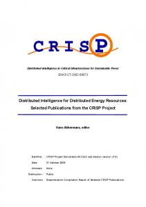
F. GE Universal Interconnect Prototype The GE Universal Interconnect (UI) is a prototype interconnection system based on the GE G60 Universal Generator protection relay from GE Multilin and a GE Zenith transfer switch. The GE UI is designed to allow the interconnection of any distributed generator with the EPS and provide a local load connection. It operates in a manner similar to the ASCO STLS and provides seamless transfer between the utility and generator to provide power to the load. IV. TEST RESULTS The testing reported in this section focuses on three requirements of IEEE 1547: response to abnormal voltage conditions, response to abnormal frequency conditions, and unintentional islanding. Tables I and II give the required clearing times for the interconnection system to respond to abnormal voltage and frequency conditions. TABLE I
RESPONSE TO ABNORMAL VOLTAGE
Voltage Range (Based on 480 V)
Clearing Time (s)
V