nels (Rambus RDRAM interface was assumed). Our models include the effects of not only L2 banks and memory controllers, but also DMA controllers and Non-.
In Proceedings of the 32nd International Symposium on Computer Architecture, June 2005
Interconnections in Multi-core Architectures: Understanding Mechanisms, Overheads and Scaling �
Rakesh Kumar , Victor Zyuban , Dean M. Tullsen Department of Computer Science and Engineering University of California, San Diego La Jolla, CA 92093-0114
�
IBM TJ Watson Research Center 1101 Kitchawan Road Yorktown Heights, NY 10598
problem. This is because power, area, latency, and bandwidth are all first-order design constraints for on-chip interconnects. Secondly, the design choices for the cores, caches, and interconnect interact to a much greater degree. For example, an aggressive interconnect design consumes power and area resources that then constrains the number, size, and design of the cores and caches. Thus, unlike a conventional multiprocessor, performance is not necessarily maximized by the highest bandwidth interconnect available. Of course, the converse is also true, that the number and type of cores (as well as onchip memory) also dictate requirements on the interconnect. In fact, increasing the number of cores places conflicting demands on the interconnect – requiring higher bandwidth while decreasing available real estate. In this paper, we model the implementation of several interconnection mechanisms and topologies, allowing us to quantify their area, power, and latency overheads. We highlight the various tradeoffs between performance and power, and between performance and area. We study the sensitivity of these overheads to technology, pipeline depth, number of cores, and onchip memory sizes. We also present one novel interconnection architecture which effectively exploits some of the behaviors identified by this research – a hierarchical bus structure that reduces local communication overheads, at the expense of cross-chip latencies. All of this work is done in the context of important commercial workloads. This study has three primary goals: (1) to study on-chip interconnect architectures with detailed and accurate models that go well beyond prior published work in this area, (2) to use those models to explore the design space of interconnect architectures, including crossbars, point-to-point connections, bus architectures, and various combinations of those technologies at different widths, and (3) to demonstrate that neither the core/cache architectures nor the interconnect architecture can be derived independently, but that the best design is a result of careful co-design of each of these elements. The results of this research deliver several strong messages for architects of future multi-core systems. First, the interconnect is a critical design element of a multi-core architecture. On an 8-core processor, for example, the interconnect, even under conservative assumptions can consume the power equivalent of one core, take the area equivalent of three cores,
Abstract This paper examines the area, power, performance, and design issues for the on-chip interconnects on a chip multiprocessor, attempting to present a comprehensive view of a class of interconnect architectures. It shows that the design choices for the interconnect have significant effect on the rest of the chip, potentially consuming a significant fraction of the real estate and power budget. This research shows that designs that treat interconnect as an entity that can be independently architected and optimized would not arrive at the best multicore design. Several examples are presented showing the need for careful co-design. For instance, increasing interconnect bandwidth requires area that then constrains the number of cores or cache sizes, and does not necessarily increase performance. Also, shared level-2 caches become significantly less attractive when the overhead of the resulting crossbar is accounted for. A hierarchical bus structure is examined which negates some of the performance costs of the assumed baseline architecture.
1 Introduction High-performance processor architectures are moving towards designs that feature multiple processing cores on a single chip. These designs have the potential to provide higher peak throughput, easier design scalability, and greater performance/power ratios than monolithic designs. At least two dual-core architectures [15, 16] are already on the market. However, in spite of the growing trend to put multiple cores on the die, a deep understanding is lacking in the literature of the design space of the interconnection framework, and particularly how it interacts with the rest of the multi-core architecture. For a given number of cores, the “best” interconnection architecture in a given chip multiprocessing environment depends on a myriad of factors, including performance objectives, power/area budget, bandwidth requirements, technology, and even the system software. This paper attempts to present a comprehensive analysis of the design issues for a class of chip multiprocessor interconnection architectures. While interconnects are relatively well understood for connecting chips, multi-chip modules, and board-level nodes, connecting cores on the same chip presents a distinctly different A more detailed version of this paper appears as [20]
1
and add delay that accounts for over half the L2 access latency. Second, co-design of the cores, caches and interconnect is critical to achieving the best architecture. We show, for example, one configuration where decreasing the bandwidth of the interconnect increases performance, due to the complex interplay of performance and area on a chip multiprocessor. As another example, when interconnect overheads are taken into account, sharing L2 cache among multiple cores is significantly less attractive than when these factors are ignored. Even with fourway sharing of L2 caches, the interconnect can be as much as a quarter of the chip area. In fact, we show repeatedly in this research that design decisions made ignoring the impact of the interconnect are often the opposite of the decision indicated when these factors are properly accounted for. The rest of this paper is organized as follows. Section 3 discusses the various interconnection mechanisms. Sections 4 and 5 discuss the methodological details for this study. Sections 6 and 7 present overhead analysis for various interconnection mechanisms. Section 8 discusses scaling of these overheads as a function of technology and pipeline depth. An example interconnection optimization is presented in Section 9. Section 10 concludes.
the context of on-chip multiprocessors with on-chip interconnects.
3
Interconnection Mechanisms
3.1
Shared Bus Fabric
In this paper, we study three interconnection mechanisms that may serve particular roles in our interconnect hierarchy – a shared bus fabric (SBF) that provides a shared connection to various modules that can source and sink coherence traffic, a point-to-point link (P2P link) that connects two SBFs in a system with multiple SBFs, and a crossbar interconnection system. Many different modules may be connected to these fabrics, which use them in different ways. But from the perspective of the core, an L2 miss goes out over the SBF to be serviced by higher levels of the memory hierarchy, another L2 on the same SBF, or possibly an L2 on another SBF connected to this one by a P2P link. If the core shares L2 cache with another core, there is a crossbar between the cores/L1 caches and the shared L2 banks. Our initial discussion of the SBF in this section assumes private L2 caches. The results in this paper are derived from a detailed model of a complex system, which are described in the next few sections. The casual reader may want to skim Sections 3 through 5 and get to the results in Section 6 more quickly.
2 Related Work
There have been several proposals and implementations of high-performance chip multiprocessor architectures [5, 12, 15, 16]. The proposed interconnect for Piranha [5] was an intrachip switch. Cores in Hydra [12] are connected to the L2 cache through a crossbar. In both cases, the L2 cache is fully shared. IBM Power4 [15] has two cores sharing a triply-banked L2 cache. Connection is through a crossbar-like structure called the CIU (core-interface unit). In this paper, we consider bus-based and crossbar-based interconnections. There have been recent proposals for packetbased on-chip interconnection networks [13, 7, 25]. Packetbased networks structure the top level wires on a chip and facilitate modular design. Modularity results in enhanced control over electrical parameters and hence can result in higher performance or reduced power consumption. These interconnections can be highly effective in particular environments where most communication is local, explicit core-to-core communication. However, the cost of distant communication is high. Due to their scalability, these architectures are attractive for a large number of cores. The crossover point where these architectures become superior to the more conventional interconnects studied in this paper is not clear, and is left for future work. There is a large body of related work evaluating tradeoffs between bus-based and scalable shared memory multiprocessors, in the context of conventional (multiple-chip) multiprocessors. Some earlier implementations of the interconnection networks for multiprocessors have been described in [10, 31, 23, 27, 26, 11, 2, 22, 3]. However, on-chip interconnects have different sets of tradeoffs and design issues. Thus, the conclusions of those prior studies must be re-evaluated in
A Shared Bus Fabric is a high speed link needed to communicate data between processors, caches, IO, and memory within a CMP system in a coherent fashion. It is the on-chip equivalent of the system bus for snoop-based shared memory multiprocessors [10, 31, 23]. We model a MESI-like snoopy writeinvalidate protocol with write-back L2s for this study [4, 15]. Therefore, the SBF needs to support several coherence transactions (request, snoop, response, data transfer, invalidates, etc.) as well as arbitrate access to the corresponding buses. Due to large transfer distances on the chip and high wire delays, all buses must be pipelined, and therefore unidirectional. Thus, these buses appear in pairs; typically, a request traverses from the requester to the end of one bus, where it is queued up to be re-routed (possibly after some computation) across a broadcast bus that every node will eventually see, regardless of their position on the bus and distance from the origin. In the following discussion a bidirectional bus is really a combination of two unidirectional pipelined buses. We are assuming, for this discussion, all cores have private L1 and L2 caches, and that the shared bus fabric connects the L2 caches (along with other units on the chip and off-chip links) to satisfy memory requests and maintain coherence. Below we describe a typical transaction on the fabric. 3.1.1 Typical transaction on the SBF A load that misses in the L2 cache will enter the shared bus fabric to be serviced. First, the requester (in this case, one of the cores) will signal the central address arbiter that it has a request. Upon being granted access, it sends the request over 2
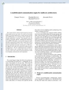
in determining what cycle access is granted. Overhead of the arbiter includes control signals to/from the requesters, arbitration logic and some latches. After receiving a grant from the central arbiter, the requester unit puts the address on the address bus. Each address request goes over the address bus and is then copied into multiple queues, corresponding to outgoing P2P links (discussed later) and to off-chip links. Being a broadcast bus, the address bus spans the width of the chip. There is also a local snoop queue that queues up the requests and participates in the arbitration for the local snoop bus. Every queue in the fabric incurs at least one bus cycle of delay. The minimum size of each queue in the interconnect (there are typically queues associated with each bus) depends on the delay required for the arbiter to stall further address requests if the corresponding bus gets stalled. Thus it depends on the distance and communication protocol to the device or queue responsible for generating requests that are sinked in the queue, and the latency of requests already in transit on the bus. We therefore compute queue size based on floorplan and distance. The snoop bus can be shared, for example by off-chip links and other SBFs, so it also must be accessed via an arbiter, with associated delay and area overhead. Since the snoop queue is at one end of the address bus, the snoop bus must run in the opposite direction of the address bus, as shown in Figure 1. Each module connected to the snoop bus snoops the requests. Snooping involves comparing the request address with the address range allocated to that module (e.g., memory controllers) or checking the directory (tag array) for caches. A response is generated after a predefined number of cycles by each snooper, and goes out over the response bus. The delay can be significant, because it can involve tag-array lookups by the caches, and we must account for possible conflicts with other accesses to the tag arrays. Logic at one end of the bidirectional response bus collects all responses and broadcasts a message to all nodes, directing their response to the access. This may involve sourcing the data, invalidating, changing coherence state, etc. Some responders can initiate a data transfer on a read request simultaneously with generating the snoop response, when the requested data is in appropriate coherence state. The responses are collected in queues. All units that can source data to the fabric need to be equipped with a data queue. A central arbiter interfacing with the data queues is needed to grant one of the sources access to the bus at a time. Bidirectional data buses source data. They support two different data streams, one in either direction. Data bandwidth requirements are typically high. It should be noted that designs are possible with fewer buses, and the various types of transactions multiplexed onto the same bus. However, that would require higher bandwidth (e.g., wider) buses to support the same level of traffic at the same performance, so the overheads are unlikely to change significantly. We assume for the purpose of this paper that only the above queues, logic and buses form a part of the SBF and
Core
(incl. I$/D$)
L2
AB SB
D-arb
A-arb
Book
RB
keeping
DB
Figure 1. The assumed shared bus fabric.
an address bus (AB in Figure 1). Requests are taken off the end of the address bus and placed in a snoop queue, awaiting access to the snoop bus (SB). Transactions placed on the snoop bus cause each snooping node to place a response on the response bus (RB). Logic and queues at the end of the response bus collect these responses and generate a broadcast message that goes back over the response bus identifying the action each involved party should take (e.g., source the data, change coherence state). Finally, the data is sent over a bidirectional data bus (DB) to the original requester. If there are multiple SBFs (e.g., connected by a P2P link), the address request will be broadcast to the other SBFs via that link, and a combined response from the remote SBF returned to the local one, to be merged with the local responses. Note that the above transactions are quite standard for any shared memory multiprocessor implementing a snoopy writeinvalidate coherence protocol [4]. 3.1.2 Elements of the SBF The composition of the SBF allows it to support all the coherence transactions mentioned above. We now discuss the primary buses, queues and logic that would typically be required for supporting these transactions. Figure 1 illustrates a typical SBF. Details of the modeled design, only some of which we have room to describe here, are based heavily on the shared bus fabric in the Power 5 multi-core architecture [16]. Each requester on the SBF interfaces with it via request and data queues. It takes at least one cycle to communicate information about the occupancy of the request queue to the requester. The request queue must then have at least two entries to maintain the throughput of one request every cycle. Similarly, all the units that can source data need to have data queues of at least two entries. Requesters connected to the SBF include cores, L2 and L3 caches, IO devices, memory controllers, and non-cacheable instruction units. All requesters interface to the fabric through an arbiter for the address bus. The minimum latency through the arbiter depends on (1) the physical distance from the central arbiter to the most distant unit, and (2) the levels of arbitration. Caches are typically given higher priority than other units, so arbitration can take multiple levels based on priority. Distance is determined by the actual floorplan. Since the address bus is pipelined, the arbiter must account for the location of a requester on the bus 3
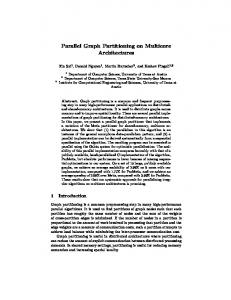
Crossbar interface logic presents a simplified interface to the instruction fetch unit and the Load Store Unit in the cores. It Core typically consists of a load queue corresponding to each core sharing the L2. The load queue sends a request to the L2 bank AB(one per core) DoutB(one per core) appropriate to the request, where it is enqueued in a bank load DinB(one per bank) queue (BLQ) (one per core for each bank to avoid conflict between cores accessing the same bank). The BLQs must arbitrate for the L2 tags and arrays, both among the BLQs, as well as with the snoop queue, the writeback queue, and the data L2 bank reload queue — all of which may be trying to access the L2 at the same time. After L2 access (on a load request), the data goes through the reload queue, one per bank, and over the data Figure 2. A typical crossbar bus back to the core. The above description of the crossbar contribute to the interconnection latency, power, and area overinterface logic is based on the crossbar implementation (also heads. called core interface unit) in Power4 [15] and Power5 [16]. Note that even when the caches (or cache banks) are shared, 3.2 P2P Links an SBF is required to maintain coherence between various units in the CMP system. If there are multiple SBFs in the system, the connection between the SBFs is accomplished using P2P links. Multiple 4 Modeling Area, Power, and Latency SBFs might be required to increase bandwidth, decrease signal Both wires and logic contribute to interconnect overhead. latencies, or to ease floorplanning (all connections to a single This section describes our methodology for computing various SBF must be on a line). For example, if a processor has 16 overheads for 65nm technology. The scaling of overheads with cores as shown in Figure 3, it becomes impossible to main- technology as well as other design parameters is discussed in tain die aspect ratio close to 1 unless there are two SBFs each Section 8. supporting 8 cores. Each P2P link should be capable of transferring all kinds of 4.1 Wiring Area Overhead transactions (request/response/data) in both directions. Each We address the area overheads of wires and logic separately. P2P link is terminated with multiple queues at each end. There The latency, area, and power overhead of a metal wire deneeds to be a queue and an arbiter for each kind of transaction pends on the metal layer used for this wire. Technology that described above. we consider facilitates 10 layers of metal, 4 layers in 1X plane and 2 layers in the higher planes (2X, 4X and 8X) [17]. The 3.3 Crossbar Interconnection System 1X metal layers are typically used for macro-level wiring [17]. The previous section assumed private L2 caches, with com- Wiring tracks in higher layers of metal are very expensive and munication and coherence only occurring on L2 misses. How- only used for time-critical signals running over a considerable ever, if our architecture allows two or more cores to share L2 distance (several millimeters of wire). cache banks, a high bandwidth connection is required between We evaluate crossbar implementations for 1X, 2X and 4X the cores and the cache banks. This is typically accomplished metal planes where both data and address lines use the same by using a crossbar. It allows multiple core ports to launch metal plane. For our SBF evaluations, the address bus, snoop operations to the L2 subsystem in the same cycle. Likewise, bus, and control signals always use the 8X plane. Response multiple L2 banks are able to return data or send invalidates to buses preferably use the 8X plane, but can use the 4X plane. the various core ports in the same cycle. Data buses can be placed in the 4X plane (as they have more The crossbar interconnection system consists of crossbar relaxed latency considerations). All buses for P2P links are links and crossbar interface logic. A crossbar consists of ad- routed in the 8X plane. dress lines going from each core to all the banks (required for The area occupied by a bus is determined by the number of loads, stores, prefetches, TLB misses), data lines going from wires times the effective pitch of the wires times the length. each core to the banks (required for writebacks) and data lines We account for the case where the area of one bus (partially) going from every bank to the cores (required for data reload subsumes the area of some other bus in a different plane. as well as invalidate addresses). A typical implementation, When buses are wired without logic underneath, repeaters and shown in Figure 2, consists of one address bus per core from latches are placed under the buses without incurring any adwhich all the banks feed. Each bank has one outgoing data ditional area overhead. However, when interconnection buses bus from which all the cores feed. Similarly, corresponding to are routed over array structures (e.g. cache arrays, directories each write port of a core is an outgoing data bus that feeds all etc.), we account for the fact that the sub-arrays (or memory the banks. macros) have to be shifted to make space for the placement of 4
Metal Plane 1X 2X 4X 8X
Pitch (� m) 0.2 0.4 0.8 1.6
Signal Wiring Pitch (� m) 0.5 1.0 2.0 4.0
Repeater Spacing (mm) 0.4 0.8 1.6 3.2
Repeater Width(� m) 0.4 0.8 1.6 3.2
Latch Spacing (mm) 1.5 3.0 5.0 8.0
Latch Height ( � m) 120 60 30 15
Channel Leakage per repeater (uA) 10 20 40 80
Gate Leakage per repeater(uA) 2 4 8 10
Table 1. Design parameters for wires in different metal planes
wire repeaters and latches. In this case the minimal repeater and latch spacing is an essential parameter determining the area overhead. We believe that 4X and 8X wires can be routed over memory arrays. However, in section 7, we also evaluate routing 1X and 2X over memory, even though we believe it to be technologically more difficult. Table 1 shows the signal wiring pitch for wires in different metal planes for 65nm. These pitch values are estimated by conforming to the considerations mentioned in [29]. The table also shows the minimum spacing for repeaters and latches as well as their heights for computing the corresponding area overheads. We model the height of the repeater macro to be 15 � m. The height of the latch macro given in the table includes the overhead of the local clock buffer and local clock wiring, but excludes the overhead of rebuffering the latch output which is counted separately. The values in Table 1 are for a bus frequency of 2.5 GHz and a bus voltage of 1.1 V. Analysis for different bus frequencies can be found in Section 8.
and the local clock distribution, but does not include rebuffering that typically follows latches. Total dynamic power of a bus would depend on utilization of the bus as well as the efficacy of clock gating. We assume that in 30% of the unused cycles the latches will be gated off, to be consistent with clock gating efficiencies typically quoted for high-end microprocessors [6]. Even though the cycles of inactivity are easier to predict in the fabric than in the core, the physical distance between latches of the neighboring clock stages is much larger in the fabric, which complicates the timing of the clock gate signals. Repeater leakage is computed using the parameters given in Table 1. For latches, we estimate channel leakage to be 20uA per bit in all planes (again not counting the repeaters following a latch). Gate leakage for a latch is estimated to be 2uA per bit in all planes [1]. For computing dynamic and leakage power in the queues, we use the same assumptions as for the wiring latches.
4.2
4.4
Logic Area Overhead
Area overhead due to interconnection-related logic comes primarily from queues. Queues are assumed to be implemented using latches. We estimate the area of a 1-bit latch used for implementing the queues to be ������� � for 65nm technology [30]. This size includes the local clock driver and the area overhead of local clock distribution. We also estimated that there is 30% overhead in area due to logic needed to maintain the queues (such as head, tail pointers, queue bypass, overflow signaling, request/grant logic, etc.) [6]. The interconnect architecture can typically be designed such that buses run over interconnection-related logic. The area taken up due to wiring is usually big enough that it (almost) subsumes the area taken up by the logic. Because queues overwhelmingly dominate the logic area, we ignore the area (but not latency) of multiplexors and arbiters. It should be noted that the assumed overheads can be reduced by implementing queues using custom arrays instead of latches. 4.3
Latency
The latency of a signal traveling through the interconnect is primarily due to wire latencies, wait time in the queues for access to a bus, arbitration latencies, and latching that is required between stages of interconnection logic. Latency of wires is determined by the spacing of latches. Spacing between latches for wires is given in Table 1. Arbitration can take place in multiple stages (where each stage involves arbitration among the same priority units) and latching needs to be done between every two stages. For 65 nm technology, we estimate that no more than four units can be arbitrated in a cycle. The latency of arbitration also comes from the travel of control between a central arbiter and the interfaces corresponding to request/data queues. Other than arbiters, every time a transaction has to be queued, there is at least a bus cycle of delay — additional delays depend on the utilization of the outbound bus.
5
Modeling multi-core architectures
For this study, we consider a stripped version of out-of-order Power4-like cores [15]. We determine the area taken up by such a core at 65nm to be �� � � �� . The area and power determination methodology is similar to the one presented in [19]. The power taken up by the core is determined to be 10W, including leakage. For calculating on-chip memory sizes, we use the Power5 cache density, as measured from die photos [16], scaled to 65nm. We determine it to be 1 bit per square micron, or
Power
Power overhead comes from wires, repeaters, and latches. For calculating dynamic dissipation in the wires, we optimistically estimate the capacitance per unit length of wire (for all planes) to be 0.2 pF/mm [14]. Repeater capacitance is assumed to be 30% of the wire capacitance [1]. The dynamic power per latch is estimated to be 0.05 mW per latch for 2.5 GHz at 65 nm [30]. This includes the power of the local clock buffer 5
����������������� ��!
large number of operating system services and access large databases. These characteristics make the instruction and data working sets large. These workloads are also inherently multiuser and multitasking, with frequent read-write sharing. We use PowerPC instruction and data reference traces of the workloads running under AIX. The traces are taken in a nonintrusive manner by attaching a hardware monitor to a processor [9, 21]. This enables the traces to be gathered while the system is fully loaded with the normal number of users, and captures the full effects of multitasking, data sharing, interrupts, etc. These traces contain even DMA instructions and non-cacheable accesses.
. For the purpose of this study, we consider L2 caches as the only type of on-chip memory. We do not assume off-chip L3 cache, but in 65nm systems, it is likely that L3 chips would be present as well (the number of L3 chips would be limited, however, due to the large number of pins that every L3 chip would require), but we account for that effect using somewhat optimistic estimates for effective bandwidth and memory latency. Off-chip bandwidth was modeled carefully based on pincount [1] and number of memory channels (Rambus RDRAM interface was assumed). Our models include the effects of not only L2 banks and memory controllers, but also DMA controllers and Noncacheable Instruction Units (NCUs) on the die that can generate transactions. NCUs handle instructions like syncs, eieios (enforce inorder execution of I/Os), TLB invalidates, partial read/writes, etc., that are not cached and are directly put on the fabric. Each core has a corresponding NCU. The assumptions about these units are taken from Power 4 and Power 5 [15, 16] designs. We simulate a MESI-like [24, 15] coherence protocol, and all transactions required by that protocol are faithfully modeled in our simulations. We also model weak consistency [8] for the multiprocessor, so there is no impact on CPI due to the latency of stores and writebacks. For performance modeling, we use a combination of detailed functional simulation and queuing simulation tools [21]. The functional simulator is used for modeling the memory subsystem as well as the interconnection between modules. It takes instruction traces from a SMP system as input and generates coherence statistics for the modeled memory/interconnect subsystem. The queueing simulator takes as input the modeled subsystem, its latencies, coherence statistics and the inherent CPI of the modeled core assuming perfect L2. It then generates the CPI of the entire system, accounting for real L2 miss rates and real interconnection latencies. Traffic due to syncs, speculation, and MPL (message passing library) effects is accounted for as well. The tools and our interconnection models have been validated against a real, implemented design. The cache access times are calculated using assumptions similar to those made in CACTI [28]. Memory latency is set to 500 cycles. The average CPI of the modeled core over all the workloads that we use, assuming perfect L2, is measured to be 2.65. Core frequency is assumed to be 5GHz for the 65nm studies. Buses as well as the L2 are assumed to be clocked at half the CPU speed. 5.1
6
Shared Bus Fabric Overheads, Performance, and Design Considerations
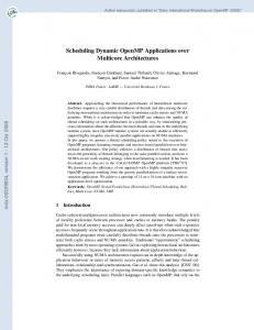
This section examines the various overheads of the shared bus fabric, and the implications this has for the entire multicore architecture. We examine floorplans for several design points, and characterize the impact on the overall design and performance of the processor of the area, power, and latency overheads. This section demonstrates that the overheads of the SBF can be quite significant. It also illustrates the tension between the desire to have more cores, more cache, and more interconnect bandwidth, and how that plays out in total performance. In this section, we assume private L2 caches and that all the L2s (along with NCUs, memory controllers, and IO Devices) are connected using a shared bus fabric. We consider architectures with 4, 8, and 16 cores. Total die area is assumed to be ��������! due to yield considerations. Hence, the constant at " amount of L2 per core decreases with increasing number of cores. For 4, 8 and 16 cores, we evaluate multiple floorplans and choose those that maximized cache size per core while maintaining a die aspect ratio close to 1. In the default case, we consider the width of the address, snoop, response and data buses of the SBF to be 7, 12, 8, 38 (in each direction) bytes respectively — these widths are determined such that no more than 0.15 requests get queued up, on average, for the 8 core case. We also evaluate the effect of varying bandwidths. We can lay out 4 or 8 cores with a single SBF, but for 16 cores, we need two SBFs connected by a P2P link. In that case, we model two half-width SBFs and a 76 byte wide P2P link. Figure 3 shows the floorplans arrived at for the three cases. The amount of L2 cache per core is 8MB, 3MB and 0.5MB for 4, 8 and 16 core processors respectively. It must be mentioned that the 16-core configuration is somewhat unrealistic for this technology as it would result in inordinately high power consumption. However, we present the results here for completeness reasons. Wires are slow and hence cannot be clocked at very high speeds without inserting an inordinately large number of latches. For our evaluations, the SBF buses are cycled at half the core frequency.
Workload
All our performance evaluations have been done using commercial workloads, including TPC-C, TPC-W, TPC-H, Notesbench and others further described in [21]. The server workloads used represent such market segments as on-line transaction processing (OLTP), business intelligence, enterprise resource planning, web serving, and collaborative groupware. These applications are large and function rich; they use a 6
CORE
CORE
L2Data
CORE
L2Data
L2Data
CORE
NCU
NCU
L2Data L2Data
CORE
NCU
NCU
L2Data
MC
IOX
SBF
MC
IOX
MC
MC
L2Data L2Data
IOX
MC
SBF
MC
IOX
CORE L2Data
NCU NCU
L2Data
CORE
NCU
NCU
CORE
NCU
CORE
IOX
SBF
L2Data
MC NCU NCU
CORE
CORE
CORE
CORE
L2Data L2Data
CORE
CORE
CORE
CORE
L2Data
MC
CORE L2Data L2Data
CORE
NCU NCU
NCU NCU
CORE
L2Data
CORE L2Data
CORE
MC
L2Data MC
CORE
NCU NCU
NCU NCU
L2Data
L2Data L2Data
NCU NCU
NCU
L2Data
SBF
NCU NCU
L2Data
CORE
IOX
MC
CORE
L2Data
NCU NCU MC NCU NCU
CORE
L2Data L2Data
CORE
CORE
L2Data
Figure 3. Floorplans for 4, 8 and 16 core processors 60
Architected busses
Control wires
Number of cores Number of data queue latches Number of request queue latches Number of snoop queue latches Number of latches for response bus queue Total number of latches Area(in >?>?@ )
Total overhead
Area overhead(mm^2)
50 40 30
8 45056 4928 336 1680 52000 8.6
16 92160 8512 896 6720 108288 17.94
Table 2. Logic overhead
The graph also shows that area overhead increases quickly with the number of cores. This result assumes constant width architected buses, even when the number of cores is increased. If the effective bandwidth per core is kept constant, overhead would increase even faster. The overhead due to control wires is high. Control takes up at least 37% of SBF area for 4 cores and at least 62.8% of the SBF area for 16 cores. This is because the number of control wires grows linearly with the number of connected units, in addition to the linear growth in the average length of the wires. Reducing SBF bandwidth does not reduce the control area overhead, thus it constrains how much area can be regained with narrower buses. Note that this argues against very lightweight (small, low performance) cores on this type of chip multiprocessor, because the lightweight core does not amortize the incremental cost to the interconnect of adding each core. Interconnect area due to logic is primarily due to the various queues, as described in Section 4. Table 2 shows the area overhead due to interconnect-related logic and the corresponding breakdown. The area taken up by interconnection-related logic increases superlinearly with the number of connected units (note that the number of connected units is 14, 22 and 38 respectively for 4, 8 and 16 core processors). When going from 8 to 16 cores, the logic-area overhead jumps because the queues are required to support two SBFs and a P2P link. Note, however, that the logic can typically be placed underneath the SBF wires. Thus, under these assumptions the SBF area is dominated by wires, but only by a small amount.
20 10 0 4
6.1
4 28672 3136 336 1680 33824 5.6
8
Number of cores
16
Figure 4. Area overhead for shared bus fabric. Area
The area consumed by the shared bus fabric comes from wiring and interconnection-related logic, as described in Section 4. Wiring overhead depends on the architected buses and the control wires that are required for flow control and arbitration. Control wires are needed for each multiplexor connected to the buses and signals to and from every arbiter. Flow control wires are needed from each queue to the units that control traffic to the queue. Since data buses run in the 4X plane, the area taken up by (76-byte) data buses is calculated as #�$ %'& (�)�& *�&�+-,�.0/2143 , which results in #�576 8�#�% %�9 . Address (7 bytes), snoop (12 bytes), response buses (8 bytes) as well as control wires (at least 198 of them for the stated control architecture for 8 cores) that run in the 8X plane can be routed over the data buses. In this case, the area overhead of the data buses is subsumed by that of the remaining buses. For 16 cores, the P2P links do not result in direct area overhead because they can be routed over L2 caches. However, reduction in the cache density (due to bus latches and repeaters) does result in an area overhead. Figure 5 shows the wiring area overhead for various processors. The graph shows the area overhead due to architected wires, control wires, and the total. We see that area overhead due to interconections in a CMP environment can be significant. For the assumed die area of 5�:�:�%�%;9 , area overhead for the interconnect with 16 cores is 13%. Area overhead for 8 cores and 4 cores is 8.7% and 7.2% of the die area, respectively. Considering that each core is