CREWS Report Series 97-08
Introducing Genericity and Modularity of Textual Scenario Interpretation in the Context of Requirements Engineering
Camille Ben Achour, Colette Rolland Centre de Recherche en Informatique Université de Paris 1 - Sorbonne
CRI, 17 rue de Tolbiac 75013 Paris - France
{rolland, camille}@univ-paris1.fr
Introducing Genericity and Modularity of Textual Scenario Interpretation in the Context of Requirements Engineering1 Camille Ben Achour, Colette Rolland Centre de Recherche en Informatique Université de Paris 1 - Sorbonne 17, rue de Tolbiac 75013 Paris - France
[email protected]
Abstract : This paper attempts to define the role and the constraints of Natural Language (NL) interpretation within the Requirement Engineering (RE) process. In so doing, it addresses two key features of a NL interpretation tool. First, genericity towards the design modelling language targeted by the interpretation can be supported owing to the semantic level of analysis of the input scenario. Genericity allows to interpret any kind of textual scenario into any kind of target design model. The second characteristic of the interpretation tool is its modularity which permits to automate partly RE tasks. Tightly embedded in the RE process, the interpretation becomes a powerful support that participates efficiently to the automation of numerous RE tasks. We illustrate this feature with an example making use of the interpretation tool for the improvement of the consistency between sequence diagrams and textual scenarios.
1.
Introduction
Design modelling languages (e.g. Entity Relationship, sequence diagrams [Jacobson 95], UML, etc) have a fixed syntax and semantics, ambiguity is reduced, and many processes such as normalisation, viewpoints integration, animation, or transformation into more formal specification languages. These languages were defined by the Requirement Engineering (RE), Software Engineering (SE) and Human Computer Interface (HCI) communities to express formally the requirements for a new system. But current practice shows that the stakeholders (customer, system user, etc.) feel uncomfortable with such languages. Inevitably, Natural Language (NL) appears as a convenient communication medium at the early phases of the RE process. This is confirmed by recent research on scenarios which has shown that nearly all scenario-based approaches are, at least partially, using text [Rolland et al. 97]. In practice, the co- existence of semi-formal or formal design modelling languages and NL is difficult : how to ensure the consistency between textual and formal products, how to use NL as a way to improve or reach an agreement on formal products, how to retrieve a formal specification starting from a scenario (and vice 1This work is partly funded by the European Community under ESPRIT Reactive Long Term
Reasearch CREWS (21.903). CREWS stands for Cooperative Requirements Engineering With Scenarios.
versa), how to ensure the quality of textual scenarios ? The position we adopt in this paper is that a tool dedicated to the interpretation of textual scenarios can be used to achieve most of these RE issues. The key intention of this paper is to present the integration of such a tool into the RE process. In order to support this integration, the design of the interpretation tool emphasises two main properties : genericity and modularity. Genericity with respect to the target language, allows the interpretation tool not to be dedicated to any specific methodology or product design modelling language. Modularity of the interpretation tool is related to its ability to be embedded and used in many steps of the RE process. In the next section, we show how the genericity feature can be supported by an interpretation tool. Section 3 introduces the NATURE meta-model for modelling of RE processes, and describes a way to integrate the interpretation tool in these processes. Section 4 presents an example of use of the interpretation tool in the framework of the RE process. Discussion and conclusion are developed in section 5. 2.
The Process of Scenario Interpretation
Numerous instruments and experiments of requirements elicitation based on linguistic techniques have been developed in the last fifteen years. The common characteristics of these solutions lay in the goal of interpreting requirements expressed in NL to generate products expressed in some specific formal or semi-formal design modelling language. One can distinguish three levels of linguistic analysis for the interpretation of NL texts. Lexical level instruments perform the linguistic analysis on words or sequences of words of input texts. [Goldin and Berry 94] described a method for identifying frequently used words or clauses by a statistical analysis technique inspired from signal processing. The output is a list of words and clauses that can be seen as a first draft of a list of entities. Even successful, this method is restricted to the analysis of large documents. Indeed it is inadequate for short texts like an intervention within a dialogue, or scenarios for which statistics data are not relevant. Techniques which perform the linguistic analysis at the syntactic level use equivalence relationships between syntactic structures -or grammatical functions- of the NL, and structures of the target design models to perform abstraction. For example, [Chen 83], [Vadera and Meziane 94], [Sykes 95] have respectively discussed the links between typical structures of the English grammar and Entity Relationship (ER), VDM and NIAM diagrams. A more recent trend is turned towards on the derivation of object oriented models with similar techniques [Saeki et al 89], [Kristen 94], [Liang and Palmer 94]. The number of such successful experimentations suggests that the use of syntactic analysis is sufficient for the interpretation purpose. However, it is widely recognised that the grammatical and syntactical levels of analysis of natural language lead to huge difficulties due to ambiguity. One can thus differentiate the deep level of analysis which qualifies the semantic roles that words, or groups of
words, play in the sentence, from the surface level (syntactic or grammatical level) which is only related to the grammatical functions of these elements. Our position is that the deep level of linguistic analysis is required in the process of extracting semiformal or formal requirements out of the short texts, like scenarios, which emerge during the RE process. This position may be related to the third type of instruments, namely semantic instruments, such as [Bouzeghoub et al 85] [Bouzeghoub 92] who described an expert system based on a semantic model for the design of relational databases. However, it is closer to [Rolland and Proix 92] (and in some way to [Belkouche and Kozma 93] [Ohnishi 96]) which define mappings between grammars for the representation of the deep level of NL and different design modelling languages. Moreover, a major drawback of these tools is that they are specific to the design modelling language they are associated to. On the contrary the interpretation technique proposed in this paper is designed in order to allow the generation of products expressed in any design modelling language, and to be integrated in any RE process in which it can be helpful. 2.1.
The Semantic Analysis of Natural Language
The key purpose of the interpretation activity is to identify candidate instances of some design model out of input NL statements. Within the scope of the RE process, these statements are scenarios, that is to say descriptions of the Information System under development (its structure, behaviour, goals, organisational context, etc.), but they could also be part of the numerous dialogues that occur during the RE process : questions, answers, explanations, illustrations, refutations, etc. To perform the interpretation of so different kinds of statements requires to reach the semantic level of NL analysis. As proposed in successful experiments quoted above, we have selected the approach of Fillmore's Case Grammar2 for the semantic analysis of natural language texts [Ben Achour 97]. The Case Grammar, introduces mainly a finite set of semantic cases (such as agent, object, source, destination, instrument, etc.). These cases are defined as the semantic roles that the different elements of an action clause play with respect to the central verb. One must notice that the cases of the Case Grammar are different from grammatical functions. In the sentence "the potatoes are boiling" the grammatical subject potatoes is semantically the object of the action whereas in "John is boiling the potatoes", the subject identifies semantically the agent of the action. The semantic cases agent and object are thus different from the grammatical functions subject and direct object. Indeed the purpose of the semantic cases is to remove the ambiguity introduced by grammatical functions. In the Case Grammar, the agent is the entity which undertakes or controls the action, and the object is the entity
2The Case Grammar was first proposed by Fillmore in 1968 as a universal definition of the language
semantics. It has been many times revisited; [Shanck 73], [Wilks 77], [Simmons 73], [Boguraev and Spark-Jones 87], [Dik 89], have also inspired my research.
which undergoes the action. These definitions are orthogonal to the grammatical that the corresponding elements can take in the sentence. Whereas certain semantic cases like agent or object are associated to any action verb, some cases are specific to certain types of verbs. The source (respectively the destination) is, for instance, the location of the object at the beginning (at the end) of transfer actions. An important result of the Case Grammar is that verbs which have a similar meaning are used with similar semantic structures. Indeed, verbs expressing an action of transfer (like ''to give', ''to take'', ''to move'', ''to enter'', etc.) always express the moving of an object, initiated by a agent, from a source to a destination. We define thus, case patterns as typical semantic structures. Case patterns are represented as templates associating a semantics to the different elements of a sentence. At the level of clauses case patterns are clause semantic patterns associated to verbs. They can identify actions (like the transfer actions) and static relationships (like the state, the localisation, or the ownership). Clause patterns have the form N (V) [C], where N is equal to the name of the pattern qualifying the intrinsic semantics of the verb V, and C is the list of cases of the pattern to which are associated the corresponding element of the analysed clause. For example, Transfer (V) [Agent; Object; Source; Destination] is the clause pattern for transfer actions. Applying this pattern to the analysis of the clause ''The computer transmits the call data to the dispatcher'' gives thefollowing result (instantiated pattern) : Transfer (''transmit'') [Agent : ''computer''; Object : ''call data''; Source : ''computer''; Destination : ''dispatcher''].
In addition to clause semantic patterns, we define sentence semantic patterns. Sentence patterns, (like the constraint, the sequence, or the trigger) contrarily to clause patterns define the semantic relationships between clauses or sentences of a same text. For example the sentence pattern constraint relates a condition to any other constrained sentence or clause. Its representation is thus : Constraint [Condition; Constrained] In "the computer transmits the call data to the dispatcher unless the controller has already recorded the same call in the computer" the second clause of the sentence expresses a constraint on the first clause of the sentence. Like clause patterns, sentence patterns are identified owing to cues such as conjunctions (''if', ''when'', ''before'', ''after'', etc.) or equivalent fixed expressions (''under the condition that'', ''at the moment of''). The recursive definition of sentence patterns allows to identify the semantics of complex sentences. In "the computer prints a form with the call data and transmits the call data to the dispatcher unless the controller has already recorded the same call in the computer", the constrained sentence is not only a simple clause, but a sentence expressing the sequence of two action clauses. Any sentence pattern may itself be embedded in another sentence pattern. This is the case in the sentence "when the controller launches the computer, this one prints a form with the call data and transmits the call data to the dispatcher unless the controller has already recorded the same call in the computer", where the
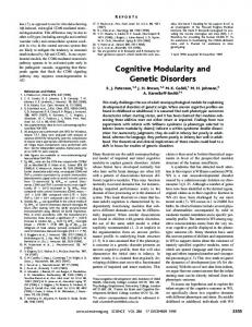
constraint ("unless the controller has already recorded the same call in the computer") on the sequence of two actions ("this one prints a form with the call data to the dispatcher") is related to the triggering event ("when the controller launches the computer") through the trigger sentence pattern. Sentence patterns provide a way to define the semantics of the relationships between the different subsentences of complex semantic sentences. However, at the surface level, the different component subsentences may appear in syntactically separated sentences. Indeed it often happens that, for the sake of understanding, sentences which are semantically related are syntactically separated. The relationship between the two sentences is then made explicit, like in "The form is copied. Then, it is transmitted to the dispatcher", where "then" allows to identify the sequencing of the two actions. An important property of semantic patterns is univocity. Indeed, semantic patterns give a unique deep level representation to support the meaning of texts. On the contrary, natural language often provides many alternative ways of expressing the same facts. However restricted by the syntactic rules, the sequencing of words at the surface level of a sentence may vary without affecting the deep level of that sentence. Consider for example the sequence of three actions A1, A2 and A3. Two sequence patterns will be used to express this sequence : action A1 precedes action A2, and action A2 precedes A3. On the contrary, there are six different ways of presenting these actions in a sentence without affecting its meaning. (1) First A1. Then A2. Then A3. (2) First A1. Then A3. But between A1 and A3, A2. (3) A2. Before A2, A1. After A2, A3. (4) A2. Then A3. But before A2, A1. (5) A3. Before A3, A1. But between A1 and A3, A2 (6) A3. Before A3 A2. And before A2 A1. The taxonomy of clause and sentence patterns presented in Fig 1 was defined following Boguraev and Spark-Jones pragmatic approach [Boguraev and Spark-Jones 87]. The identification of semantic patterns was first issued from the analysis of the set of exercises we submit to our BA and MA students at the University of Paris 1 France. These exercises contain textual descriptions of information systems to model with the Entity Relationship and the Remora design models. This ontology of semantic patterns has been successfully applied to 15 textual scenarios written by students of the City University (UK) in the framework of lectures on object oriented modelling3. It does not cover all the semantics which may be extracted out of NL texts. Tense, numeration, negation, word semantics, anaphora, and other usual elements of the semantics of NL cannot expressed, but we am currently working on the 3 I would like to thank Dr N.A.M. Maiden (City University, London, UK) who selected
and provided these scenarios.
search for new extensions according to the needs of the semantic definition of several design modelling languages.
Fig 1 : taxonomy of semantic patterns The process of text analysis is linear and does not require any intervention of the user if there is no syntactic or semantic ambiguity. At the beginning, each sentence is analysed separately. If the sentence is only a simple clause, the semantic analysis is performed in two steps. First, the clause is rewritten in a normalised structure. Second, the normalised clause is unified with the clause semantic pattern associated to its verb. This leads to the emergence of an instantiated clause pattern for the entire sentence. If the sentence is composed of several clauses, sentence semantic cues are identified, and each clause is analysed separately as stated above. Then the global structure of the sentence is normalised, and unified with the structure of the relevant sentence semantic patterns. 2.2.
Producing Instances of the Concepts of Several Target Design Modelling languages
Many previous attempts to instantiate design modelling languages from NL texts have emphasised the relationships between word categories or grammatical cases and modelling primitives. In an ER model, verbs usually correspond to relationships, nouns tend to serve as entities and adjectives as attributes. As argued in [J.A. Gulla et al 97], we feel that such an approach "does not catch the deeper semantic relationships that are needed for a satisfactory mapping to model constructions". In our approach, we perform the linguistic interpretation of modelling patterns by the means of logical formulas referring to linguistic semantic patterns. The assumption is that the characteristic templates of a design modelling language, i.e. model patterns, can be analysed as equivalents to semantic patterns of the case grammar. When the semantics of parts of a textual scenario match with the semantics of a model pattern, we know that these elements might be understood as the instances of the model pattern. However, we cannot be sure that they should be interpreted as this particular pattern in the model. Due to fuzzyness and ambiguit of NL expressions, we have to check if the scenario parts can be interpreted as instances of several patterns of the target design modelling language. For example in an ER model, the age of a person may be either an entity related to the person by some ''has'' relationship, or a simple attribute of
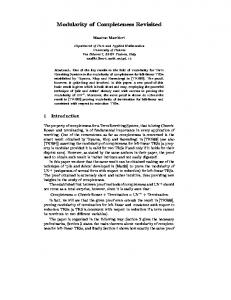
the ''person'' entity. If several interpretations are possible, the interpretation tool has to produce the different results as alternative model pattern instances, so that the user can select the most appropriate one. To perform the generation, the interpretation tool uses production rules similar to the ones defined in the domain of deductive databases [Fabret and Simmon 94]. The effect of the execution of these production rules is the generation of parts of products by instanciation of patterns of the target design modelling language. We have defined (Fig. 3) the set of rules for the production of candidate parts of sequence diagrams [Jacobson 95] from textual scenarios. A sequence diagram (see Fig. 2) is a sequence of interactions between the system and its external actors. Actors can be people or systems, and the designed system is itself treated as a single actor. An event is an instantaneous one to one communication. At the simplest, an event is the sending of a message from an actor to the system and vice versa. Broadcast, asynchronous communications, parallelism, branching and alternatives are omitted, but are ordered by a strict partial ordering relationship noted before. 1,N
from
1,1
Actor
Event 1,N
to
1,1
has
1,N
Message
1,1 0,N
0,N
before Fig. 2 : ER diagram of the sequence diagram model. The production rules (1) to (7) underneath are formulae with the form Qt : Cs / Cm → P, where : - Cs is a first order logical formula expressing a condition on the semantics of the input textual scenario. The semantics is expressed by case patterns as explained above. The terms [a..z; A..Z], used to denote the variable parameters of the case patterns, are quantified if needed at the beginning of the rule (''Qt :'') with the operators of universality (∀) and existence (∃). In order to lighten the reading of the rules, stars are used to replace one or several free terms. The special predicate ''Unify(X, Y)'' is used to compare the terms of the condition and to check if two terms unify. The logical operators used to express the formula Cs are the ones of the first order logic : ∧, ∨, ¬, ⇒, ⇔, etc. - Cm is a logical formula expressing a condition on parts of the product that have already been generated. The language used for this formula is the same as the one used for Cs, except that the predicates apply on the target design model and not on semantic patterns. - P describes the set of instances of patterns of the target model that can be produced if Cs and Cm are both true. ''Produced'' is here taken in the sense of a close world in which any predicate which has not been produced is supposed to be false, and any predicate which is produced is supposed to be true.
The rules (1) - (7) allow to produce the three types of concepts of the sequence diagram model (namely Actors, Events and Messages) with their names and relationships out of the semantics of textual scenarios. (1) ∀ V, A, O, S, D : Transfer (V) [Agent : A; Object : O; Source : S; Destination : D] ∧ (Unify (A, S) ∨Unify (A, D)) / true → Event (e), From (e, S), To (e, D), Message (e, O), Unify (e, V) If there is, in the scenario statements, a transfer action in which the agent is also either the source, or the destination of the object, then there is, in the sequence diagram, an event going from the source to the destination of the transfer action. The name of the event is the verb of the transfer action and the message is its object. For example the sentence ''the controller has already recorded the same call in the computer'' is semantically analysed with the pattern : Transfer (record) [Agent : ''controller; Object : ''call''; Source : ''controller''; Destination : ''computer'']. Applying the rule (1) to this clause pattern generates an event ''record'' from the ''controller'' to the ''computer'' with the message ''call''. (2) ∀ V, A, ∃ O : Action (V) [Agent : A; Object O] / Actor (O) → Event (e), From (e, A), To (e, O), Unify (e, V) If there is, in the scenario, an action in which the object is an agent in the sequence diagram, then there is in the sequence diagram an event from the agent to the object of the action. The name of the event is equal to the name of the action. Thus if the ''computer'' has already been instantiated as an actor, the sentence ''the controller launches the computer'' which is an action (Action (launch) [Agent : ''controller''; Object : ''computer'']) allows to generate the event ''launch'' from the actor ''controller'' to the actor ''computer''. (3) ∀ t, s, V1, V2, A, e1 : Trigger (t, s) ∧ Unify (t, Action (V1) [Agent : A; *]) ∧ Unify (s, Action (V2) [*]) / Event (e1) ∧ From (e1, A) ∧ Unify (e1, V1) → Event (e2), Before (e1, e2), Unify (e2, V2) If there is, in the scenario, a trigger sentence, in which the triggering action corresponds to an event in the sequence diagram, then each instance of this event in the sequence diagram is followed by an event corresponding to the triggered action. This rule applies to the sentence ''when the controller launches the computer, this one transmits the call data to the dispatcher'' if the ''launch'' action has already been interpreted as an event starting from the actor ''controller''. Applying the rule produces an event ''transmit'' which follows the event ''launch''.
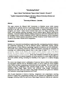
(4) ∀ t, s, V1, V2, A1, A2, e1, e2 : Sequence (t, s) ∧ Unify (t, Action (V1) [Agent : A1; *]) ∧ Unify (s, Action (V2) [Agent : A2; *]) / Event (e1) ∧ From (e1, A1) ∧ Event (e2) ∧ From (e2, A2) and Unify (e1, V1) and Unify (e1, V2) → Before (e1, e2) If there is in the scenario statements a sequence of two actions which has been interpreted as events in the sequence diagram, then the two events are sequenced, as identified in the scenario. (5) ∀ A : Action (*) [Agent : A; *] / true → Actor (A) To each agent of any kind of actions of the scenario statements corresponds an actor in the sequence diagram. We have seen at rule (2) that the clause ''the controller launches the computer'' is an action with an agent ''controller''. The same semantic pattern applied to rule (5) produces the actor ''controller'' in the sequence diagram. (6) ∀ e, F : true / Event (e) ∧ From (e, F) → Actor (F) In the sequence diagram, each source of event corresponds to an actor. For example if the rule (1) generates an event ''transmit'' to the ''computer'', starting from the clause ''the computer transmits the call data to the dispatcher'', then the ''computer'' actor is generated owing to this rule. (7) ∀ e, T : true / Event (e) ∧ To (e, T) →Actor (T) In the sequence diagram, each target of event corresponds to an actor. Similarly to rule (6), this rule will generate the actor ''dispatcher'' if the dispatcher has already been interpreted as the target of the event ''transmit''. The process of mapping semantic patterns to model patterns is straightforward. Once semantic analysis is performed, the production rules are tried out for each model pattern as long as a product part can be produced. The evaluation of the production rules conditions is supported by the unification of the predicates of these conditions with the semantic patterns of the input text and with the parts of the product that have already been produced. All the clause patterns, sentence patterns -and the patterns they include- are tried out until the end of the text is reached. Several semantic patterns can be used to instantiate respectively simple or complex model patterns, and a single semantic pattern can serve to instantiate several model patterns. Each time a semantic pattern of the initial text is used for producing a product part, the corresponding statement is marked in the input scenario. Fig. 3 illustrates the application of the interpretation process. A scenario is interpreted onto a sequence diagram.
Fig. 3 : example of production of a sequence diagram by the interpretation tool The use of the interpretation tool can thus be seen asa function call with two parameters : the scenario to analyse, and the set of rules for the instantiation of the target design modelling language. The genericity of the interpretation tool is due to the genericity of the production rules. Indeed, the Cm and the P parts of the production rules can refer to any predicate participating to the description of a model pattern. Production rules can thus be written for the generation of any target design modelling language. The ability to generate several design modelling languages is illustrated by the three following rules extracted from the set of production rules dedicated to the ER model. (1) ∀ V, A, O : Action (V) [Agent : A; Object : O] / true → Association (a), Role (r1), Has (a, r1), Role (r2), Has (a, r2), Entity(e1), Relate (r1, e1), Entity (e2), Relate (r2, e2), Unify (e1, A), Unify (e2, O), Unify (r1, V) If there is an action in the scenario, then there is in the ER diagram an association with two roles, respectively related to an entity corresponding to the agent, and to an entity corresponding to the object of the action. The name of the association is equal to the name of the action verb.
(2) ∀ V, O1, O2 ∃ e1 : Ownership (V) [Owner : O1; Owned : O2] / Entity (e1) ∧ Unify (e1, O2) → Association (a), Role (r1), Has (a, r1), Role (r2), Has (a, r2), Entity (e2), Relate (r1, e2), Relate (r2, e1), Unify (e2, O2), Unify (e2, O), Unify (r1, V) If there is in the scenario an ownership relationship, in which the owned object is an entity in the ER diagram, then there is in the ER diagram an association with two roles, respectively related to an entity corresponding to the owner, and an entity corresponding to the owned object. The name of the association is equal to the name of the ownership verb. (3) ∀ V, O1, O2 : Ownership (V) [Owner : O1; Owned : O2] / true → Entity (e), Attribute (a), Has (e, a), Unify (e, O1), Unify (a, O2) If there is in the scenario an ownership relationship, then there is in the ER diagram an entity named by the owner with an attribute named by the owned object of the ownership relationship. The result of the interpretation process is twofold. First, it identifies a set of product parts instantiating the target design modelling language, and second it identifies a set of statements of the input scenario that have not been used during the interpretation process. A part of the input scenario may have not been interpreted either because it is ambiguous, or because it has no equivalent in the target design model . When the process of interpretation is completed, several decisions can thus be taken : (1) to modify the input scenario in order to make it consistent with the output product, (2) to modify the output product in order to have it complete and validated, (3) to integrate it or make consistent with an other product part, (4) to search for an agreement on the output product, etc. 3.
Integrating the Interpretation Tool into the RE Process
An approach to generate guidance centred process models was proposed by the Nature European Research Project [Rolland 95]. Authors refer to these models as "ways of working" since they are intended to guide the user in their way of working to solve a design problem. In [Rolland, Plihon 95], Rolland presents a meta-modelling approach in which a given way of working is constructed by instantiation of a process meta-model allowing to deal with a large variety of situations in a flexible and decision oriented manner. Based on the properties of the meta-model, ways of working can be formally defined with an appropriate level of genericity, and in a modular way to facilitate their evolution and improvement. They are designed for providing automated and flexible guidance in decision making during the process. WeI believe that the proposed approach is convenient for the description of the interpretation process model in the context of a RE process. 3.1.
The Process Meta Model
Fig. 4 presents a global view of the process meta model using a binary ER-like notation..
Fig. 4 : overview of the process meta-model The central concept of this meta-model is the one of context which associates a situation with the decision. A situation is a condition on a part of the product that defines a product state it has sense to make a decision on. Situations can identify product states at various detail granularity levels : they can be either atomic like an object class attribute, or they can be coarse grained like contingency factors or a complete scenario. A decision expresses some goal that the users of the process want to achieve. In the following, I often relate decisions to intentions. A decision reflects the "choice" that a user makes at some moment in the RE process, in order to achieve the intention he has in mind. The description of decisions can include objects of the situation, the desired result, the manner to perform an upper-level decision, and time or location statements; ''identify actor in scenario'', ''described event'', ''create sequence diagram'' are examples of decisions. Contexts are defined by the couple . Acting in a context corresponds to a step in the process : in a given situation, and in order to progress in the process, the user has to make a decision. As shown in the figure, contexts can be linked repeatedly in a hierarchical manner to define trees. A process model is therefore a forest of trees 3.2.
The different types of contexts
A situation exists at different levels of granularity. Furthermore, decisions have consequences which differ from one granularity level to another. The different contexts are classified according to their consequences in the meta-model into executable, plan and choice contexts. 3.2.1.
Choice context
A user may have several alternative ways to fulfil a single decision in a single situation. He has therefore to select the most appropriate amongst the set of possible choices. In order to model this piece of knowledge, we introduce the first type of context, namely the choice context. The execution of such a context consists in choosing one of its alternatives, i.e. selecting a context which represents a particular approach for the resolution of the issue raised by the decision made in the context. Arguments and choice criterion for the assistance of the decision making are associated to refinement links. Both are described in detail in [Rolland 95]. It is important to notice that the alternatives of a choice context are contexts with the same situation. For example, fig. 5 shows that the decision ''Identify Event in Scenario'' can be reached either by identifying the event ''by Manual Selection'' in the scenario of the situation, or by using an approach of ''Automated Interpretation''. The automated interpretation approach for the identification of an event makes usage of the interpretation tool presented in section 2 by parametring it with a set of production rules restricted to the ones allowing to identify events. More generally, owing to its modularity and genericity, the interpretation tool can be used to support the automated approach of any context having an ''Identification'' decision.
Fig. 5 : an example of choice context 3.2.2.
Plan context
In order to represent contexts requiring to make a set of complementary decisions, the modelling formalism includes a second type of context called the plan context. A plan context can be looked upon as a complex issue which is decomposed into complementary sub-issues, each of which corresponds to a sub-decision associated to a component situation. The component context of a plan contexts can be of any type : executable, choice or plan. In the process meta-model, the decomposition of a plan context into its more elementary component contexts is represented by the composition link relationship. These links are completed by precedence links which allow to define the ordering of the component contexts. [Rolland 95] defines precedence graphs in association to plan contexts in order to allow a precise specification of this ordering. Fig. 6 illustrates the plan context with an example in which at least two of the three sub-contexts make use of the interpretation tool in a different configuration. Indeed, similarly
to the context ''Couple Actors to Event'', the ''Identify Event'' and the ''Identify Actor'' context may benefit of the interpretation tool modularity by using a set of production rules restricted to the ones allowing to identify in the scenario the actors related to the event of the situation, before performing the coupling.
Fig 6 : an example of plan context 3.2.3.
Executable context
At the most detailed level, the execution of any process can be seen as a set of transformations of the product or its associated information, each transformation resulting from the execution of deterministic actions. Such an action is a consequence of a decision made in a certain context. This leads to the concept of an executable context as an individual block of the way of working, individual in the sense that it can not be refined nor decomposed. Executable contexts correspond to the leaves of the trees constituting a way of working. An executable context operationalises an atomic decision by performing the associated action or a set of actions. Actions are thus the implementation of decisions. Performing an action changes the product and may generate a new situation which is itself, subject to new decisions. 3.2.4.
The concept of action
Actions are classified under two main types : atomic and compound actions. A compound action is defined as the predetermined sequence of actions in which there is no relevant decision to be made. The actions included in compound actions can be atomic actions or themselves compound actions. It is important to notice that compound actions can not substitute plan or choice contexts. Indeed the decision defined in an executable context is atomic : it requires neither refinement nor decomposition from the point of view of the granularity level of the way of working it belongs to. Examples of atomic actions are : delegation of a decision, transaction opening / closure, or messaging of a dialogue intervention, etc. NL analysis and product production, as w have presented them in section 2 are also atomic actions. The genericity feature of the interpretation tool shows its interest here. It allows us, whenever there is in a way of working a context having an associated decision of product identification, to refine it by the ''Identify by Automated Interpretation'' executable context. This context uses the interpretation tool as
associated action, and this whatever the target design modelling language is. The other feature of the interpretation tool, namely the modularity, allows us to integrate the interpretation tool into any way of working. This provides the possibility to perform the text interpretation with a selected subset of the production rules associated to a target design modelling language. As an illustration of the former, he process model supporting the interpretation of a scenario in order to produce a sequence diagram is presented in fig. 7. The construction, definition and description of an event diagram uses the interpretation tool, but only for specific concepts of the target design modelling language at a time, and this either in relation with an existing part of the product, or in isolation. See[Rolland and Plihon 96] for a detailed explanation of the process model.
fig 7 : process model for the definition of a sequence diagram with usage of the interpretation tool. 4.
An Application Example
The purpose of this example is to show the integration of the interpretation tool in a RE process model whose goal is to improve the consistency between a textual scenario Sc and a sequence diagram Sd. The root context of this process model (fig. 8) is a plan context refined by four contexts which goals are respectively to : - construct a sequence diagram Sd' corresponding to the textual scenario Sc, - reduce the difference between Sc and Sd', - improve the inclusion of the scenario in the sequence diagram Sd, using Sd', - and improve the inclusion of the sequence diagram Sd in the scenario, using Sd'.
The inclusion relationship between two sequence diagrams is similar to the set inclusion, taking for hypothesis that sequence diagrams are sets of concepts (events, actors, messages, and the relationships which are attached to them). Having a product included in an other product means that all the concepts of the included product appear in the including product. The construction of Sd' from the initial scenario Sd is defined in a process model similar to the one described in the previous section. It strongly relies on the use of the interpretation tool which operationalises the identification, naming and linkage of events, actors and messages. The two ''Improve Inclusion'' contexts are plan contexts with a similar structure. The context ''Improve Inclusion of Sd' into Sd '' proposes to perform three tasks : identify an event in Sd, try to identify the same event in Sd', and if necessary reduce the difference between Sd and Sd'. These components appear in both contexts, but the reduction of the differences is performed differently depending on the product to modify. In order to reduce the difference between Sd' and Sd several decisions can be taken : rephrase the non interpreted sentences of Sd, delete them, move them into another deliverable or into another part of the same deliverable, or simply highlight them for future work. The context of event identification in a sequence diagram offers the choice between manual selection and automated identification. Automated identification is an executable context that performs the action of unification of the event with each of the events of the sequence diagram. The automated identification can be convenient if the sequence diagram is large, but manual selection is useful in case of failure. Several alternative decisions can be taken if Sd' is not included in Sd : delete, rephrase, move or highlight the sentences of Sc corresponding to supplementary information (events, actors, messages and from/to/before relationships of Sd'), but also add them to Sd. If Sd is not included in Sd', it is possible to add in Sc sentences describing the supplementary knowledge of Sd. This can be done by rephrasing, refining or adding sentences into the scenario. It can also be decided to modify Sd in order to reduce its content; by deleting the supplementary events actors or messages, or by merging two events, two actors or two messages.
fig. 8 : process model for the improvement of the consistency between a textual scenario and a sequence diagram.
This process model relies to a large extend on the use of the interpretation tool. Primarily for the creation of a sequence diagram equivalent to the scenario ; Secondly fo the refinement of an event identified in the scenario by decomposition into several sub events, involves also the interpretation tool. Once the decomposition has been made explicit in the scenario, the new sentences are interpreted and the produced knowledge incorporated to the sequence diagram.
5.
Conclusion
The natural language interpretation technique presented here is intended to support the early stages of requirements engineering, where textual products such as scenarios are numerous and issues are vague and difficult to formalise. Its major advantage is that it automates the management of the relationships between textual and (semi-) formal products in an adaptable, generic way. It is generic in the sense that the technique is indépendant of the design modelling language. It is adaptable in the sense that the natural language interpretation can be targeted to any concept of a given design modelling language. Scenarios expressed in natural language are analysed at the semantic level and formal products are generated in a deductive manner. These two functions of the interpretation process are formally described in the interpretation process model, and can be easily integrated in RE process models. The interpretation technique is inspired from [Rolland and Proix 92], and the process modelling approach was developed in the NATURE Project (N°5363) [Rolland 95][Rolland, Plihon 95][Rolland et la 95]. The prototype implementation of the interpretation tool is under development and its potential usage studied in the CREWS Project [Ben Achour 97]. Future works will concentrate on three topics. Firstly, linguistic research on the extension of the set of semantic patterns is needed to ensure full genericity. The case based approach to text analysis necessitates to extend the coverage of the semantics field currently taken into account. The question is whether the semantic analysis is precise and complete enough to ensure the equivalence with any design model pattern. Secondly, the reverse functions of the interpretation tool - namely product paraphrasing - can be used to support other requirements engineering processes like the production of documentation or other deliverable. Lastly, the interpretation tool is integrated into mono-operative requirements engineering process models. The interpretation could be used to support co-operative work if the process meta-model is extended to co-operation and the analysis adapted to support dialogue interventions. The dialogue is currently limited to the menu-based selection of decisions during process guidance. Natural language based dialogue interpretation will be very beneficial. We plan to extend and adapt Grice's dialogue model [Grice 75] to support the interpretation of dialogue interventions expressed in natural language.
6.
References
[Belkhouche and Kozma 93] B. Belkhouche, J. Kozma. Semantic Case Analysis of Informal Requirements. Proceedings of the 4th Workshop on the Next Generation of CASE Tools, The Netherlands, pp 163-182, 1993. [Ben Achour 97] C. Ben Achour. Linguistic Instruments for the Integration of Scenarios in Requirements Engineering. Proceedings of the 3rd Int. Workshop on Requirements Engineering : Foundation of Software Quality, Barcelona, 1997. [Boguraev and Spark-Jones 87] B. Boguraev, K. Spark-Jones. A Note on a Study of Cases. In Computational Linguistics, Vol 13, n° 1-2, pp 65-68, 1987. [Bouzeghoub et al 85] M. Bouzeghoub, G. Gardarin, E. Métais. Database Design Tools an Expert System Approach. Proceedings of the 11th Conference on Very Large Databases, Stockholm, pp82-95, 1985. [Bouzeghoub 92] M. Bouzeghoub. Using Expert Systems in Schema Design. In Conceptual Modelling, Database and CASE: an Integrated View of Information Systems, (ed P. Loucopoulos and R. Zicari), Wiley, 1992. [Chen 83] P.S. Chen. English Sentence Structure and Entity Relationship Diagrams. Information Sciences, 29, pp 127-149, 1983. [Dik 89] S.C. Dik. The Theory of Functional Grammar, Part I : the Structure of the Clause. Functional Grammar Series, Vol 9, Foris Publications, 1989. [Fillmore in 1968] C. Fillmore. The Case For Case. In Universals in Linguistic Theory, Bach & Harms, Chicago, Eds Holt, Rinehart and Winston, pp 1-90, 1968. [Goldin and Berry 94] L. Goldin, D.M Berry. AbstFinder, a Prototype Abstraction Finder for Natural Language Text for Use in Requirements Elicitation: Design, Methodology and Evaluation. Proceedings of ICRE'94, first International Conference on Requirement Engineering, Colorado, pp 84-93, 1994. [Grice 75] H.P. Grice. Logic and Conversation. In Syntax and Semantics 3 : Speech Acts, eds Coles and Morgan, Academic Press, New York, pp41-58, 1975. [Gulla et al] J.A Gulla, B. Van der Vos, U. Thiel. An Abductive Linguistic Approach to Model Retrieval. Data and Knowledge Engineering Vol. 23 n° 1, pp. 17 - 31. June 1997 [Jacobson 95] I. Jacobson. The Use Case Construct in Object-Oriented Software Engineering. In Scenario Based Designed : Envisioning Work and Technology in System Development. John Wiley and Sons, Ed J.M. Caroll, 1995. [Kristen 94] G. Kristen. Object Orientation, the Kiss Method: From Information Architecture to Information Systems. pp 97-119, 1994. [Liang and Palmer 94] J. Liang, J.D. Palmer. A Pattern Matching and Clustering Based Approach for Supporting Requirements Transformation. Proceedings of ICRE'94, first International Conference on Requirement Engineering, Colorado, pp 180-183, 1994. [Ohnishi 96] A. Ohnishi. Software Requirements Specification Database Based on Requirements Frame Model. Proceedings of 2nd International Conference on Requirement Engineering, Colorado, pp221228, 1996. [Rolland 82] C. Rolland, C. Richard. The Remora Methodology for Information Systems Design and Management. IFIP TC8 Int. Conf. on Comparative Review of Information Systems Design Methodologies, North Holland, 1982.
[Rolland 95] C. Rolland, C. Souveyet, M. Moreno. An Approach for Defining Ways-of-Working. In Information Systems Journal, Vol 20 no 4, pp 337-359, 1995. [Rolland et al. 97] C. Rolland, M. Jarke, A. Suttcliffe, E. Dubois et la. A Framework for Classifying Scenarios. CREWS deliverable W1.1. [Rolland and Plihon 96] C. Rolland, V. Plihon. Using Generic Method Chunks to Generate Process Models Fragments. Proceedings of the 3rd Int. Conf. on Requirements Engineering, 1996. [Rolland and Proix 92] C. Rolland, C. Proix. Natural Language Approach to Conceptual Modelling. In Conceptual Modelling, Database and CASE: an Integrated View of Information Systems, (ed P. Loucopoulos and R. Zicari), Wiley, 1992. [Saeki et al 89] M. Saeki, H. Horai, H. Enomoto. Software Development Process from Natural Language Specification. Proceedings of the 11th International Conference on Software Engineering, pp 64-73, 1989. [Shanck 73] R. Shanck. Identification of Conceptualisations Underlying Natural Language. In Computer Models of Thought and Language, Shanck & Colby, Freeman, San Francisco, pp 187-247, 1973. [Simmons 73] R. Simmons. Semantic Networks : their Computation and Use for Understanding English Sentences. In Computer Models of Thought and Language, Schanck & Colby, Freeman, San Francisco, pp 63-113. [Sykes 95] J.A.Sykes. English Grammar as a Sentence Model for Conceptual Modelling using NIAM. Information System Concepts, Towards a Consolidation of Views. Proceedings of the IFIP international working conference on information system concepts, (ed E.D. Falkenberg, W. Hesse, A. Olivé), pp161176, 1995. [Vadera and Meziane 94] S. Vadera, F. Meziane,. From English to Formal Specifications. The Computer Journal, vol 37 no 9, pp753-763, 1994. [Wilks 77] Y. Wilks. Good and Bad Arguments about Semantic Primitives. Report n° 42, Department of Artificial Intelligence, University of Edinburgh, 1977.