Islanding Prevention Scheme for Grid-Connected Photovoltaic Systems in Matlab/ Simulink Ioan Viorel Banu, Marcel Istrate “Gheorghe Asachi” Technical University of Iasi, Romania
[email protected],
[email protected]
Abstract-This paper describes the islanding phenomenon on Grid-Connected Photovoltaic (PV) Arrays for developing new techniques for islanding detection. A novel islanding prevention scheme is presented. It consists in monitoring the dc-link voltage of Voltage Source Converter (VSC). This Anti-Islanding (AI) method is validated by directly comparing the islanding detection time in various scenarios with the detection time offered by the rate of change of frequency (ROCOF) technique. Index Terms--Anti-islanding; Grid-connected photovoltaic; Islanding detection.
I.
INTRODUCTION
Islanding (also known as loss of grid or Loss-of-Mains – LoM [1]) represents “a condition in that a portion of the power system that contains both load and distributed energy resources (DER) remains energized while isolated from the remainder of the power system” [2]. Also, according to [3] a island represents a condition where a portion of an area electric power system (EPS) is energized solely by one or more local DER through the associated point of common coupling (PCC) while that portion of the area EPS is electrically separated from the rest of the area EPS [4]. Islanding appears when some part of the utility grid loses connection with the rest of the system [1]. The islanding can be intentional and unintentional [4]. An intentional island represents a planned island whereas an unintentional island is an unplanned island [3]. An unintentional island can form when a portion of the area EPS is accidentally separated from the remainder of the area EPS and the DER continues to supply power [3]. Development of sensitive and reliable AI protection is very important to encourage medium scale integration of DER into the electrical network and avoid unnecessary tripping of DER [1]. The PV inverter design will be influenced by the power grid requirements, including the anti-islanding (AI) requirement which is considered the most technically challenging [5]. One of the most challenging aspects of protection of DER is the sensitivity of islanding detection, which makes the system stable to external faults and frequency excursions [1]. Islanding for PV Power Systems appears when the power grid is tripped and the inverter does not disconnect quickly enough and continues to operate with the local load [5]. To perform islanding protection in some specific circumstances (impossibility of forming a stable island) it may be sufficient to use a combination of under/over frequency/voltage protection [1]. In most cases,
978-1-4799-6557-1/14/$31.00 ©2014 IEEE
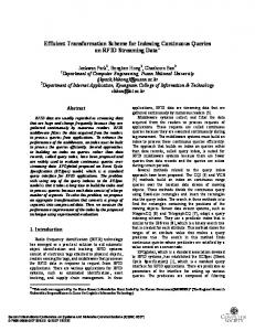
the islanding must be quickly detected and the PV System must be immediately disconnected from the power grid [5]. After disconnection, in certain scenarios the embedded generator can maintain supply to local loads or even to a small part of a network depending on its capacity and network topology [1]. In order to reduce the cost and simplify the installation of PV systems, the inverter should include effective and reliable anti-islanding procedures [6]. As the PV arrays become more popular, reliable islanding detection is becoming increasingly important. New solutions are needed as the limitations of the existing methods may eventually pose a barrier to further integration of DER [1]. Antiislanding protection involves the use of relays or controls to prevent the existence of an unintentional island [3]. The inverter must be able to detect an island, and take appropriated measure in order to protect persons and equipment [6]. IEEE standard 1547-2003 [4] requires that the DER cease to energize an unintentional island on the area EPS. If the local generator protection is unable to detect an islanding condition, a transfer trip should be installed from the upstream protective device to the generator [3]. Rate of change of frequency (ROCOF) has become the most commonly used method of islanding protection. This is a passive method based on the local monitoring of the generator voltage waveform [1]. Standard protective relays like under/over frequency protection (UFP/OFP) shield consumer’s equipment and also serve as passive AI detection methods resident in the PV inverter [7, 8]. These protection methods are low cost options for islanding detection. They may not be actually physical relays but procedures implemented in the inverter's software. All grid-connected PV inverters are required to have OFP/UFP methods to disconnect the power if the frequency of the voltage at the PCC between the customer and the utility grid is outside the prescribed limits [7]. The active AI methods are not widely utilized at this moment, due to power quality concerns [1]. The international standard IEEE 1547 [4] defines the overfrequency (OF) and under-frequency (UF) thresholds for disconnection of the DER and, in particular PV systems from the electrical network. For the European interconnected power grid (50Hz), the limits are 49.3 and 50.5Hz. According to Romanian power grid requirements for PV Systems the UF and OF trip thresholds are 49.5 and 50.5Hz [9]. Reference [10] presents a study on various islanding scenarios of a PV System. The simulation results with detection time of different AI methods are depicted in Fig. 1.
Fig. 2. Detailed Simulink model of the 100kW Grid-Connected PV System.
Fig. 1. Performance of different AI methods for a 100kW Grid-Connected PV System.
This paper presents a novel islanding prevention scheme of Grid-Connected PV Systems in Matlab/ Simulink based on monitoring the dc-link voltage of the PV inverter. A 100kW PV System equipped with islanding protection like frequency relays, a ROCOF relay, and respectively the proposed dc-link voltage relay are simulated under the conditions of islanding and the detection time for all these AI techniques are compared. The study shows under which conditions our proposed dc-link voltage AI relay is the most efficient. The presented AI detection technique consists in monitoring the dc-link voltage, which raises significantly during transient grid faults, as shown in [10]. The raise detection can be implemented in the Voltage Source Converter (VSC) control of the PV inverter that monitors the dc-link voltage. In [10] it has been determined that the optimal ROCOF threshold which should be exceeded under the conditions of islanding is 12Hz/s. Using this threshold limit, the ROCOF relay and the frequency relays are implemented in Simulink according to the requirements of international standards. The novel dc-link voltage islanding detection method proposed in this paper is simulated as well using Simulink. The time for islanding detection of the dclink voltage relay is compared with the detection time offered by ROCOF and frequency relays. The paper has the following structure. The first section presents the general description of islanding of PV Solar Power Systems. The Grid-Connected PV System and its islanding prevention scheme are described in the second section. The third section gives the theoretical simulation results of islanding conditions that are detected by AI relays. Finally, the conclusions of this study are presented. II.
The 100kW PV Array is connected to a 20kV power grid (Fig. 3) with the main frequency of 50Hz through a 100kVA 260V/20kV three-phase coupling transformer. The 5kHz dcdc step-up converter increases the dc voltage from PV maximum natural voltage of 272V to 500V, and the 2000Hz three-phase three-level VSC converts from 500Vdc to 260Vac while keeping unity power factor. The Maximum Power Point Tracking (MPPT) controller is implemented in the step-up converter, using a StateFlow implementation of incremental conductance algorithms, as described in [13]. The step-up converter controls the MPPT independently and the VSC implements dc-link voltage control for the utility grid connection [14]. The dc-link voltage is set at 500 V by the three-phase VSC.
Fig. 3. The 20kV utility grid model in Simulink environment.
B. The Simulink Implementations of Anti-Islanding Methods The Simulink block diagram of the AI protection relays on the 20kV bus are depicted in Fig. 4. The trip signals of these AI relays are disconnected from the three-phase circuit breaker CB1 of Fig. 2 on the 20kV distribution feeder at the PCC of the PV System in order to activate all relays and compare the detection times of these AI techniques. During simulation, the relays are activated only once.
THE GRID-CONNECTED PV SYSTEM AND ITS ISLANDING PREVENTION SCHEME
A. The Simulink Model of the Grid-Connected PV System The Simulink model of the 100kW Grid-Connected PV System is depicted in Fig. 2 [11]. The PV Array, formed by 330 SunPower modules [12] provides in standard test conditions (STC) a maximum power of 100.7kW and 273.5V.
Fig. 4. The Simulink model of AI relays protection bus 20kV.
The Simulink implementations of under/ over frequency relays, a ROCOF relay, and respectively the proposed dc-link voltage relay are presented in the following paragraphs. 1) The Frequency Relays The OF/UF relays monitors the frequency in the PV inverter and compare this value with some preset thresholds. The frequency relay model and its settings according to Romanian grid requirements [9] are depicted in Fig. 5.
Fig. 8. Simulink implementation of the dc-link voltage AI protection.
The dc-link voltage, Vdc_m is measured by the VSC control of the PV inverter as is presented in Fig. 9. The dc-link voltage Vdc is the output voltage of the dc-dc boost converter. The VSC controller set the reference dc-link voltage Vdc_ref at the nominal dc bus voltage Vnom_dc equal to 500V.
Fig. 5. Simulink implementation of the under/over frequency protection.
The frequency is estimated by means of the phase-locked loop (PLL) as depicted in the Fig. 6. The input is a vector containing the normalized three-phase signals of primary voltage (Va, Vb and Vc) and the output is the measured frequency (Hz) = ω / (2π).
Fig. 6. Frequency estimation.
2) The ROCOF Relay The Simulink implementation of the ROCOF relay is depicted in Fig. 7. The ROCOF relay from [10] monitors the frequency and the terminal voltage of the PV inverter. In this paper, the ROCOF protection monitors only the frequency in the PV inverter in order to calculate the ROCOF that is compared with the ROCOF threshold. The relay is activated when this condition is satisfied and the PV array is disconnected from the power grid. As in case of frequency relays the frequency for the ROCOF Relay is estimated by means of PLL. 3) The DC-Link Voltage Relay The dc-link voltage relay is implemented in Simulink as is shown in the Fig. 8. Its inputs are the dc-link voltage and the dc-link voltage threshold used for comparison. The operating principle of this AI method is very simple. The relay is activated when the dc-link voltage threshold is exceeded.
Fig. 7. Simulink model of the ROCOF relay.
Fig. 9. Measurement of the dc-link voltage.
The dc-link voltage threshold is chosen based on simulations at 10% variation of normal dc-link voltage Vnom_dc [15]. After several experiments, it was determined that increasing the threshold value of dc-link voltage, the detection time of the dc-link voltage relay increases and becomes larger than the detection time of the ROCOF relay. The optimal threshold of the dc-link voltage relay determined through simulations is also justified by the requirement to operate with a dc-link voltage as low as possible, in order to keep down the switching losses of the VSC [15]. III.
SIMULATION RESULTS OF ISLANDING CONDITIONS
The 100kW Grid-Connected PV Array from Fig. 2 is equipped with islanding protection methods like under/ over frequency relays, a ROCOF relay, and respectively the proposed dc-link voltage relay. This model is simulated using Simulink in various islanding scenarios. These scenarios are presented in the following subsections. The islanding conditions occur in the studied network from Fig. 3 when the three-phase circuit breaker CB2 is opened at time (t) = 0.1 seconds (s). The circuit breaker CB2 disconnects the utility grid from the rest of the network during 150ms. The dc-link voltages obtained for these islanding scenarios of Grid-Connected PV System are depicted in Fig. 10. It should be noted that dc-link voltage is not limited by the dc voltage protection of PV inverter. A. Scenario 1: Local Load Greater than Local Generation The values of local connected feeder loads for this scenario are shown in the utility grid model from Fig. 3. Different configurations of the connected feeder loads have different effect on dc-link voltage as shown in Fig. 11. The frequency variations and their ROCOF or df/dt, during island conditions for the same configurations of connected feeder loads from Fig. 11 are depicted in Fig. 12 and Fig. 13, respectively. As can be observed, for defaults loads and for the resistive loads these two quantities are quite close. For
capacitive reactive loads, the PV inverter loses control of the frequency. Fig. 14 presents together the frequency and ROCOF during island condition of PV system with default loads of utility grid from Fig. 3. From Fig. 14 it can be observed the effect of frequency on the islanding of PV system. During islanding condition, the frequency decreases in a very short time. Rapid change in frequency implies a certain variation of ROCOF. The islanding conditions are detected when a ROCOF threshold of 12Hz/s is exceeded. The minus sign indicates the frequency decrease.
Fig. 13. The rate of change of frequency (ROCOF) during island conditions of scenario 1 in different configuration of the connected feeder loads.
Fig. 10. The dc-link voltages in various islanding scenarios of PV System. Fig. 14. The Frequency and its rate of change of frequency (ROCOF) during island condition with default loads from Fig. 3.
The status and detection times (s) of the AI protection methods in case of this scenario are presented in Fig. 15. Each AI relay has two displays, one that shows the status of the relay (0 for inactivated and 1 for trip status) and another one indicating the trip time of the relay (time at which islanding conditions are detected). B. Scenario 2: Local Load Matches with Local Generation
Fig. 11. DC-Link Voltage during island conditions of scenario 1 in different configurations of the connected feeder loads.
Fig. 16 depicts the simulation results of dc-link voltage for scenario 2. A direct comparison between frequency and dclink voltage in case of active power is depicted in Fig. 17. It is clearly observed that the dc-link voltage variation can be much easier detected than variations of frequency, because it has a larger slope and range when islanding conditions occur.
Fig. 12. Frequency variations during island conditions of scenario 1 in different configuration of the connected feeder loads.
Fig. 15. AI Relay status and trip time (ms) in case of local connected load greater than local generation.
TABLE I DETECTION TIME OF ANTI-ISLANDING METHODS Detection Time (s) of Anti-Islanding Relays
Scenarios Local load greater than local generation Local load matches with local generation Local load less than local generation
Fig. 16. DC-Link Voltage during island conditions of scenario 2.
Fig. 17. DC-Link Voltage and frequency variation in case of resistive loads.
C. Scenario 3: Local Load Less than Local Generation The dc-link voltage variations in different cases of this scenario are depicted in Fig. 18. Considering the network configuration and its connected load, the results of scenarios in which the connected feeder load is equal or less than PV generation were very close (Fig. 16 and Fig. 18). The detection times of the AI methods analyzed in this paper for studied scenarios discussed above are given in Table I. The performance of proposed dc-link voltage relay is emphasized by comparing the detection time for all the studied relays.
Fig. 18. DC-Link Voltage during island conditions of scenario 3.
UF
OF
ROCOF
DC-Link Voltage
0.0536
–
0.0149
0.0135
–
0.0632
0.0280
0.0212
–
0.0623
0.0276
0.0222
As can be noted from Table I, the AI technique using dclink voltage relay has the fastest detection time. During islanding condition, the dc-link voltage decrease with the increase of the connected load. A small variation of inductive power does not influence much the detection time of the AI relays. The frequency relays have the limits of preset thresholds imposed by grid codes, leading to late detection of island conditions of PV systems. The detection times of islanding conditions of Grid-Connected PV System for the ROCOF relay presented in [10] are comparable with the detection times of frequency relays. The ROCOF relay implemented that in this paper has best detection times than when this AI relay is realized as in [10]. Fig. 19 depicts graphically the simulation results of AI methods discussed in this paper. It can be observed that the dc-link voltage relay offers the best detection time in all scenarios. It can also be seen that the dc-link voltage, the ROCOF, and the frequency relays are triggered in the same order in all scenarios. IV.
CONCLUSIONS
This paper presents a novel islanding prevention technique of Grid-Connected PV Systems based on monitoring the dclink voltage of PV inverter. The detection time of the islanding conditions for the frequency relays, the ROCOF relay, and respectively the proposed dc-link voltage relay are compared. This study shows under which conditions our proposed dc-link voltage AI method is the most efficient.
Fig. 19. Performance of the AI protection techniques analyzed in this paper for a 100kW Grid-Connected PV System.
REFERENCES [1] [2] [3] [4] [5] [6] [7] [8]
CIGRE, “The Impact of Renewable Energy Sources and Distributed Generation on Substation Protection and Automation,” Working Group B5.34, August 2010. IEEE Recommended Practice for Utility Interface of Photovoltaic (PV) Systems, IEEE standard 929, 2000. IEEE Standard 1547.2-2008, IEEE Application Guide for IEEE Standard 1547™, IEEE Standard for Interconnecting Distributed Resources with Electric Power Systems. IEEE Standard for Interconnecting Distributed Resources with Electric Power System, IEEE standard 1547, 2003. R. Teodorescu, M. Liserre and P. Rodríguez, Grid Converters for Photovoltaic and Wind Power Systems. John Wiley & Sons, Ltd., 2011. IEA PVPS, “Utility aspects of grid connected photovoltaic power systems,” Report IEA PVPS T5-01:1998, 1998. IEA PVPS, “Evaluation of islanding detection methods for photovoltaic utility-interactive power systems,” Task V, Report IEA-PVPS T5-09: 2002, March 2002. Ye Zhihong, A. Kolwalkar, Y. Zhang, Du Pengwei, R. Walling, “Evaluation of anti-islanding schemes based on nondetection zone concept,” Power Electronics Specialist Conference, 2003. PESC '03. 2003 IEEE 34th Annual, vol.4, pp.1735-1741, 2003
[9] [10]
[11]
[12] [13]
[14] [15]
The National Authority for the Regulation in the Energy Sector, „Technical conditions for connection to electrical networks of public interest of photovoltaic power plants – Romanian technical rule”, 2013. I. V. Banu, M. Istrate, D. Machidon and R. Pantelimon, “A study on anti-islanding detection algorithms for grid-tied photovoltaic systems,” 14th International Conference on Optimization of Electrical and Electronic Equipment, OPTIM 2014, in press. P. Giroux, G. Sybille, Hydro-Quebec Research Institute (IREQ), and C. Osorio, S. Chandrachood, The Mathworks, “100-kW Grid-Connected PV Array demo detailed model (PVarray_Grid_IncCondReg_det.mdl),” MathWorks File Exchange, 2012. https://sam.nrel.gov/ - NREL System Advisor Model. I. V. Banu and M. Istrate, “Modeling of maximum power point tracking algorithm for photovoltaic systems,” Electrical and Power Engineering (EPE), 2012 International Conference and Exposition on, 2012, pp. 953-957. K.N. Reddy and V. Agarwal, “Utility-Interactive Hybrid Distributed Generation Scheme With Compensation Feature,” Energy Conversion, IEEE Transactions on, vol.22, no.3, pp. 666-673, 2007. M. Liserre, F. Blaabjerg and A. Dell’Aquila, ”Step-by-step design procedure for a grid-connected three-phase PWM voltage source converter,” International Journal of Electronics, vol. 91, no. 8, pp. 445460, 2004.