Sep 21, 2016 - (IBM Thinkpad L421) without any special optimization. Its CPU clock speed is 2.3GHz and the memory capacity is 3GB. The software is written ...
Accepted Manuscript Iterative Optimization for Frame-by-frame Object Pose Tracking Shuang Ye, Chuancai Liu, Zhiwu Li, Abdulrahman Al-Ahmari PII: DOI: Reference:
S1047-3203(17)30017-2 http://dx.doi.org/10.1016/j.jvcir.2017.01.017 YJVCI 1937
To appear in:
J. Vis. Commun. Image R.
Received Date: Accepted Date:
21 September 2016 13 January 2017
Please cite this article as: S. Ye, C. Liu, Z. Li, A. Al-Ahmari, Iterative Optimization for Frame-by-frame Object Pose Tracking, J. Vis. Commun. Image R. (2017), doi: http://dx.doi.org/10.1016/j.jvcir.2017.01.017
This is a PDF file of an unedited manuscript that has been accepted for publication. As a service to our customers we are providing this early version of the manuscript. The manuscript will undergo copyediting, typesetting, and review of the resulting proof before it is published in its final form. Please note that during the production process errors may be discovered which could affect the content, and all legal disclaimers that apply to the journal pertain.
Iterative Optimization for Frame-by-frame Object Pose Tracking Shuang Yea,b , Chuancai Liua , Zhiwu Lic,d , Abdulrahman Al-Ahmarie,f a School
of Computer Science and Engineering, Nanjing University of Science and Technology, Nanjing 210094, China b School of Computer Science and Technology, Huaqiao University, Xiamen 361021, China c Institute of Systems Engineering, Macau University of Science and Technology, Taipa, Macau d School of Electro-Mechanical Engineering, Xidian University, Xi’an 710071, China e Advanced Manufacturing Institute, King Saud University, Riyadh 11421, Saudi Arabia f Industrial Engineering Department, College of Engineering, King Saud University, Saudi Arabia
Abstract Joint object tracking and pose estimation is an important issue in Augmented Reality (AR), interactive systems, and robotic systems. Many studies are based on object detection methods that only focus on the reliability of the features. Other methods combine object detection with frame-by-frame tracking using the temporal redundancy in the video. However, in some mixed methods, the interval between consecutive detection frames is usually too short to take the full advantage of the frame-by-frame tracking, or there is no appropriate switching mechanism between detection and tracking. In this paper, an iterative optimization tracking method is proposed to alleviate the deviations of the tracking points and prolong the interval, and thus speed up the pose estimation process. Moreover, an adaptive detection interval algorithm is developed, which can make the switch between detection and frame-by-frame tracking automatically according to the quality of frames so as to improve the accuracy in a tough tracking environment. Experimental results on the benchmark dataset manifest that the proposed algorithms, as an independent part, can be combined with some inter-frame tracking methods for optimization. Keywords: object detection, frame-by-frame tracking, pose estimation, iterative optimization, probabilistic voting
Preprint submitted to Journal of LATEX Templates
December 9, 2016
1. Introduction It is important to track objects and estimate their poses efficiently and robustly in many vision-based applications, such as Augmented Reality (AR), interactive systems, and robotic systems. Many general methods track the object 5
pose in each input frame independently by detection methods. These independent detection methods are robust but inefficient and not suitable for real-time applications. So far, some studies focus on frame-by-frame tracking methods. Compared with independent detection techniques, the frame-by-frame tracking methods exploit the temporal redundancy in the video to find the matching
10
points without the time-consuming computation for descriptors. Thus, as much as possible to prolong the frame-by-frame tracking process is helpful for real-time efficiency. Nonetheless, the tracking deviations will inevitably occur especially after complex motions. These deviations will be accumulated with continuous tracking. To avoid their influence to the results, the tracking points with a
15
large deviation should be discarded during the tracking process. On the one hand, the reduced number of points will accelerate the speed of matching, but on the other hand, some “valid” points are generally removed by mistake while some “invalid” points are still retained, which eventually leads to an estimation failure. The frame-by-frame tracking process should be interrupted when the
20
result fails, and the tracking points should be relocated by a detection method. However, it is usually difficult to determine whether the results have failed accurately. To overcome the problems, we propose a framework for pose tracking of a rigid object combining with the advantages of detection and frame-by-frame
25
tracking. This paper makes the following four contributions. First, we adjust the positions of the tracking points with a large deviation by an iteration adjustment, and make them close to the actual ones. This method improves the reliability of the tracking points and prolongs the detection interval, denoted by ∆ (i.e., the number of frames between consecutive detection frames). Second, 2
30
we propose a probabilistic model to determine whether a tracking point should be discarded or retained, in this way, those tracking points that fail to be adjusted will be removed effectively. Third, we propose a deviation score model to determine the time to stop the frame-by-frame tracking process and relocate the tracking points by a detection method. Finally, the proposed framework
35
is an independent part that can be combined with some inter-frame tracking algorithms for optimization. Experimental studies are presented to test the performance of the proposed methods in terms of speed and accuracy. The rest of the paper is organized as follows. In Section 2, related work on the detection and tracking strategies in pose estimation is reviewed. In Section 3,
40
the proposed methods are elaborated upon. Section 4 provides experiments to evaluate the developed approaches in speed and accuracy. Finally, the paper is concluded in Section 5.
2. Review of Related Work Detection Methods There are considerable studies focusing on object pose 45
or viewpoint tracking. Many of them are based on detection methods that execute object pose recognition by comparing the incoming frame with labeled images in a database. To deal with variations of an object, a database should be built in advance and have huge variations in possible viewpoints and scales. The methods in [1, 2, 3] are applied to reduce the comparison times and enhance
50
the matching speed. Even so, it is impossible to accommodate all the variations. Thus, robust feature descriptors such as SIFT (Scale-Invariant Feature Transform) [4], SURF (Speeded Up Robust Features) [5] and other SIFT-based methods [6, 7] are essential to improve the reliability of the system. Nonetheless, in most cases, the more stable the features are, the more time their detection
55
and extraction will spend. In order to improve the computational efficiency and apply the system on mobile devices, some lightweight features such as corners descriptors and binary features become popular[8, 9, 10]. Besides, The studies in [11, 12, 13, 14] use images combining RGB, depth information and other cues
3
in detection. However, in many situations these cues are not always available 60
or even unreliable [10]. In addition to the algorithms, some systems [15, 10] exploit GPU (Graphic Processing Unit) or parallel implementation to anticipate real-time performance. Detection methods perform simultaneous recognition and tracking, however, detecting robust descriptors for each frame of the video is not necessary and difficult to be accomplished at interactive frame rates [16].
65
Moreover, the detection methods usually fail when there is a significant change against the pattern frame in a database. To deal with the problem, the authors in [17] sample a group of easy instances to model the appearance of an object from the initial set of frames rather than from a database, and train an initial SVM (Support Vector Machine) detector. Then the model is used to detect the
70
harder instances of the object in the following frames. The detection results, in turn, update the detector. Nevertheless, the method is essentially based on detection and does not make full use of the temporal correlation in a video sequence. Mixed Methods Recently, some studies in [18, 19, 16, 8, 20, 21, 14] try
75
to combine detection methods with frame-by-frame tracking techniques. An detection method performs object recognition and estimates its pose in order to initialize tracking, and then algorithms are developed to exploit the correlation between video frames to track feature points at locations where they are most likely to occur in each frame. Since it is not necessary to compute descriptors
80
for the input frame while tracking, these mixed methods are more efficient at run-time. Many of them use the optical flow tracker over subsequent frames. The work offered by Horn and Schunck [22] reduces the optical flow estimation to a minimization problem of a function with a global smoothness assumption on the velocity field. This dense method calculates optical flow for each pixel in
85
the image, and is of high computational cost. To improve the speed efficiency, the method developed by Lucas-Kanade [23] computes optical flow for a sparse feature set with the assumption that all the neighboring pixels have similar motion. The local methods obtain sparse optical flow which is not accurate enough in some cases in real-world videos, such as scale variation, occlusion, 4
90
motion discontinuities and illumination changes. Thus, there have been some improvement methods. To deal with the scale variation problem, The study in [24] provides an implementation of the sparse iterative Lucas-Kanade method with pyramids. The ability of optical flow’s application in large varying illuminations is improved in [25, 26]. Several researches combine machine learning
95
techniques with optical flow to handle a large displacement task. Gaussian mixture models are applied to study statistics of optical flow in [27, 28]. The work in [29] trains a set of flow fields and estimates coefficients of a linear combination of these “basis flows” to predict optical flow. In addition, neural networks are also constructed for visual tracking or pose estimation problems [30, 31, 32].
100
However, most methods based on machine learning are not able to meet the real-time requirements in a real world application. Other motion estimations based on block matching are broadly applied in video coding and compression [33, 34, 35, 20, 21], and can be combined with the new parallel frameworks [36, 37, 38, 39] to further accelerate the system.
105
Makar, et al. [20, 21] offer a displacement model based on block matching for motion estimation. However, in this strategy of tracking, many points with large deviations are still kept in the tracking points and some of those near the real locations are discarded by mistake. The two cases above deteriorate especially when the video sequence has a complex motion. As a result, a short detection
110
interval should be set to reset the reliable keypoint set. To further prolong the detection interval, Makar et al. report a similarity transform model, an upgrade version of the displacement model. In the similarity transform model, the orientation and the scale are also concerned in the brute-force search in spite of the location. This model can improve the matching performance and prolong
115
the detection interval, however, it suffers from high computational overhead and is not suitable to meet the real-time requirements.
5
3. Proposed Methods For convenience, in this paper, the keypoints detected by the detection method are called detecting points and the matching points obtained by the 120
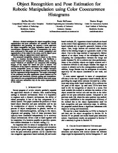
frame-by-frame tracking method are called tracking points. Tracking points can be categorized into two classes: valid and invalid ones. The valid points are those close to the locations where they should be and reliable for a pose estimation, and invalid ones are those points that deviate from the actual locations and lead to a wrong pose result. As shown in Figure 1, the 1st frame
125
is processed by a detection method and the points shown in the frame are the detecting ones. The other frames are processed by a tracking method and the points in these frames are the tracking ones. Except for the 1st frame, there are two kinds of points in the rest frames. The larger green points are valid, and the smaller red points are invalid. The pose result obtained by the valid points is
130
shown in the right side of the frame. In the 2nd and 3th frames, a small amount of invalid points begin to appear. In the continuous tracking process, the invalid points increase and deviate from their correct positions slowly. As shown in the 20th frame, in spite of some deviated points, the pose result remains effective with plenty of valid points. However, when tracking the 40th frame, due to the
135
less valid points, a deviation begins to appear in the pose result. When the number of valid points drops sharply for a jitter in the frame, there will be a large deviation in the result, as illustrated in the 55th frame. It is important to identify valid points and discard invalid points as accurately as possible, such that the detection interval is prolonged and the time ef-
140
ficiency of the system is improved. An overview of the proposed mixed tracking framework is shown in Figure 2. There are two processes in this mixed method: a detection process using SURF algorithm and a frame-by-frame tracking process. By default, the first frame in a video sequence is processed by a detection method. The subsequent frames then select one of the two methods based on
145
the pose result of the previous frame. The innovation parts of the proposed framework are marked with dotted line frames in Figure 2. The first part is a
6
�VW�)UDPH
��WK�)UDPH
�QG�)UDPH
��WK�)UDPH
�WK�)UDPH
��WK�)UDPH
�D
�E
Figure 1: Valid and invalid points in some frames of a video sequence example.
frame-by-frame tracking method named iterative optimization tracking that will reduce the deviations of the tracking points by iteratively adjusting the locations of the tracking points and discard those with a great difference by a 150
probabilistic voting model. The iterative optimization tracking can prolong the detection interval and make the pose estimation faster and more efficient. The second part is an adaptive detection interval scheme, when switching between the detection method and the frame-by-frame tracking is based on the quality evaluation of the pose result. The scheme exploits the advantages of the two
155
methods, and effectively improves the accuracy of the system. In what follows, we mainly describe the two innovations in detail. 3.1. Iterative Optimization Tracking If the valid and invalid points cannot be separated effectively, some invalid points will be treated as the valid ones and left for the pose estimation, while
160
some valid points are excluded by mistake. The high proportion of invalid points will speed up the failure in the pose estimation and cause the method to adopt a 7
D
e
t
e
c
t
i
o
n
p
r
o
c
e
s
s
A
d
a
p
t
i
v
i
Q
u
i
e
m
r
a
g
y
D
e
e
t
S
e
c
U
t
b
R
e
n
d
t
e
e
r
t
v
e
a
c
t
i
o
n
l
y
F
M
l E
a
u
a
t
e
v
s
e
E
a
t
c
g
h
t
i
m
a
o
o
d
t
d e
t
e
c
t
i
n
o
f
e
e
a
t
s
e
u
o
b
s
j
c
t
p
e
o
l u
a
i
t
y
q C
a
i
p
t
m
u
a
r
g
e
D
e
e
t
S
e
c
U
t
b
R
y
F
p
F
r
a
m
e
C
b
y
C
f
r
a
m
e
t
r
a
c
k
i
n
g
p
r
o
c
e
s
o
o
r
s
I
t
e
r
a
t
I
a
t
i
e
d
v
r
j
e
a
u
o
t
s
t
i
v
p
t
i
m
i
z
a
t
e
m
i
P
e
n
o
r
n
o
t
t
b
v
a
o
r
b
t
a
i
i
l
n
c
i
t
k
i
n
g
y
g
P
o
e
d
e
e
P
e
s
I
r
i
c
t
t
d
o
r
o
r
e
D
h
t
r
a
t
i
v
l
y
i
c
a
r
t
h
l E
a
u
a
t
e
Œȑ
v
e
s
d
s
e
d
s
s
C
e
E
a
p
t
u
r
i
n
i
t
i
a
l
l
o
c
a
t
i
oo
n
a
j
u
t
t
h
i
n
v
a
l
i
p
o
i
n
t
t
i
m
a
t
t
l i
m
a
g
e
t
o
h
ee
t
r r
a
c
k
i
n
r
a
c
k
i
n
g
l
g
c
f
a
t
i
n
o
s
t
o
o
h
e
b
y
p
r
b
f
a
b
i
i
t
o
y
b
j
e
o
c
t
p
s
e
o
l u
a
i
t
y
q
p
i
o
n
t
s
t
r
a
c
k
i
n
g
p
i
n
t
s
t
o
v
i i
n
g
o
g
o
o
d
a
n
d
dthres min(Dneigh(i) ) ≤ dthres , T Hc > dthres min(Dneigh(i) ) > dthres .
(3)
Hc where dthres is the threshold of the transfer errors, and Dneigh (i) is the set of c the transfer errors of the neighbor points based on the homography Hc . If dH i 250
is smaller than dthres , the match mi = (viP re , viT ) is thought of as being reliable Hc and receives all votes. Otherwise, it obtains votes according to Dneigh (i).
(2). p(H = Hc |v P re = viP re , M ) describes the probability of the homography Hc acquired from the correspondence V P re and V T . It is evaluated based on the average of all the transfer errors of the points, i.e.,
p(H = Hc |v P re = viP re , M ) = exp(−
P|V P re |
c dH i i=1 P re |V |
).
(4)
(3). p(v P re = viP re |M ) expresses a conditional prior for determining viP re to
255
be a valid point. Its value comes from the product of the first two probabilities of the previous frame, and we set the value of the first frame 1 for initialization. Note that the tracking solution viT after iteration in Gf −1 is treated as viP re in Gf . Algorithm 3 Discard of invalid points by probabilistic voting Input: The points to be tracked V P re in the previous frame, the probabilistic votes of previous frame P P re , the tracking points V T , the transfer errors DH , and the flags to identify the validity of the tracking points if V alids. Output: The tracking results V T , and the probabilistic votes P . begin { P = ∅; if V alids = ∅; P re ∈ V P re do for all vi pi is computed via Eq. (2); P = P ∪ {pi }; if pi < pthres then if V alidi =false; else if V alidi =true; endif if V alids = if V alids ∪ {if V alidi }; endfor Find the new set of V T by if V alids; } end
260
The process to discard the invalid points by a probabilistic voting model is formally described in Algorithm 3. Complexity The basic operations in Algorithm 1 involve two parts: (1) Iterative adjustment. In Algorithm 2, the main time consumption at each iteration is the location adjustment for every tracking point. Using the 13
265
approximate nearest neighbor search, its complexity is O(K × n), where K is the maximum number of the neighbors and n is the number of the tracking points. With the frame-by-frame tracking going on, the number of tracking points decreases and the time efficiency will be greatly improved. Furthermore, each iterative adjustment makes a percentage of the inliers that pass RANSAC
270
(Random Sample Consensus) rises continually. Since the inliers are the subset of the initial points obtained by an inter-frame tracking method, the iterative procedure should converge. The iteration terminates when the total distance between the tracking points and the projection points has no change. Since most of the frames are of normal quality generally and the individual with poor
275
quality will apply the detection method adaptively (the adaptive algorithms will be introduced in Section 3.2), more than 90% of the performance is usually achieved in early four iterations in our experiments. Thus, we only need to set a threshold of the gap between the distances of two successive iterations for termination. As a result, the complexity of Algorithm 2 is O(T × K × n),
280
where T is the maximum iteration times, and T and K are constants and much smaller than n. (2) Probabilistic voting. In Algorithm 3, the operations are mainly associated with the number n of the tracking points. Thus the complexity of the process is O(n).
285
From the above, the Algorithm 1 has the nearly linear time complexity with the number of the tracking points. Thus the proposed operations do not degrade the speed performance, and can be negligible for the overall speed improvement benefit from the longer detection interval. 3.2. Adaptive Detection Interval
290
Note that the detection result, as an initialization, is significant for the following tracking. Besides, in the frame-by-frame tracking process, the accuracy of the tracking result in the previous frame is crucial for the current frame. Therefore, it is necessary to evaluate both the detection result and the tracking result, such that we can automatically switch the tracking mode between the 14
295
detection method and the frame-by-frame method back and forth for the next frame according to the quality of the current frame. We develop an algorithm to evaluate the pose result, and the evaluation module is shown as adaptive detection interval in Figure 2. In the detection method, the number of matches will be much less than that
300
of features when the object is with severe occlusions or perspective changes. In addition, the number of features extracted by detection will drop dramatically when the quality of a frame deteriorates. Therefore, two score measures, S1 = |Mf |/|Vf | and S2 = |Vf |/|Vf0 |, are designed to evaluate the reliability of the detection result, where |Vf | and |Mf | are the numbers of features and
305
the matched features in the current frame, respectively. |Vf0 | is the number of features in the reference frame that can be chosen from the first frame or the previous frame with a reliable detection result. The results are classified into two categories by the values of S1 and S2 to guarantee the pose result delivered to the frame-by-frame tracking process.
310
In the tracking process, we switch to the detection method whenever the tracking result deteriorates. Serious deterioration of a frame always causes more deviations of the tracking points. For this reason, we design a deviation score model under the homography H to measure the degree of the deviations, i.e.,
score
H
=
P|V P re |
kviD − viH k , |V P re |
1
(5)
where viD is the i-th element of V D , viH is the i-th element of V H , and |V P re | 315
is the number of the keypoints in Gf −1 . It employs V D instead of V T , since the judgment is done at the first iteration. Besides, to avoid the accumulation of the deviations, a threshold ∆max is defined for the maximum length of the detection interval. Whether or not to continue tracking is determined by scoreH and the number of consecutive tracking frames.
320
The process of the evaluation algorithm is described in Algorithm 4. Figure 5 shows some frame sequences that apply the evaluation algorithm. In Figure 5(a), when the number of consecutive frames reaches ∆max , the tracking process
15
Algorithm 4 Adaptive evaluation method Input: The result of the pose estimation result, and the execution times of the continuous tracking counter. Output: The flag set of the state transition f lagset that includes the frame flag and the method flag for the next step. begin { (detection results evaluation) if result is a detection result then switch (result) { case good detection f : f lagset = (nextf rame, tracking); break; case poor detection f : f lagset = (nextf rame, detection); } (tracking results evaluation) else switch (result) { case good tracking f : if counter < delta max then f lagset = (nextf rame, tracking); else f lagset = (nextf rame, detection); endif break; case poor tracking f : f lagset = (nextf rame, detection); } endif } end
terminates and a detection frame is inserted in the 31th frame. In Figure 5(b), the result of a frame-by-frame tracking deteriorates in the 47th frame and we 325
terminate the tracking process and switch to detect the next frame. In Figure 5(c), the detection operation continues until a good result is acquired so as to guarantee the pose delivered to a frame-by-frame tracking.
4. Experimental Results Our experiments are designed to test whether the proposed algorithms can 330
improve the traditional inter-frame motion estimation methods in pose tracking of rigid objects. Two kinds of inter-frame motion estimation are chosen. One is the Lucas-Kanade Optical Flow in OpenCV, and the other is Makar’s displacement model which is a kind of block-matching motion estimation algorithm. These two original algorithms are compared with the improved algorithms KLT-
335
IOT and Makar-IOT in speed and accuracy. Our method is embedded in the Lucas-Kanade Optical Flow method and Makar’s displacement model, called KLT-IOT and Makar-IOT, respectively. The computing time in the following experiments involves feature detection, feature extraction, feature matching and
16
��WK�)UDPH
7UDFNLQJ
��WK�)UDPH
��WK�)UDPH
7UDFNLQJ
'HWHFWLRQ
��WK�)UDPH
7UDFNLQJ
�D ��WK�)UDPH
7UDFNLQJ
��WK�)UDPH
��WK�)UDPH
7UDFNLQJ
'HWHFWLRQ
��WK�)UDPH
7UDFNLQJ
�E ��WK�)UDPH 'HWHFWLRQ
��WK�)UDPH
��WK�)UDPH
'HWHFWLRQ
'HWHFWLRQ
��WK�)UDPH 7UDFNLQJ
�F Figure 5: The switch between a detection method and a frame-by-frame method in a adaptive evaluation algorithm.
17
pose estimation. In the detection part of these algorithms, SURF is used to ex340
tract features, and the corresponding points are found through ratio test and RANSAC. The patch size in Makar’s displacement model is 8×8 , and SADterm is 450. The experiments are based on the Stanford Streaming Mobile Augmented Reality Dataset [20]. The dataset includes 23 videos that are divided into four
345
categories: Books, CD covers, DVD covers and Objects. Each video contains 100 consecutive frames, and each frame is recorded at 30 fps with resolution 640 × 480. The corresponding ground-truth localization information of each frame is provided in advance, where a bounding quadrilateral around the object of interest is manually defined. In the experiments, four videos are chosen, each
350
from a different category. These videos are OpenCV , Barrywhite, T itanic and P olish. In order to evaluate the performance of the proposed methods under different conditions, salt and pepper noise, occlusion and illumination changes are added on the basis of the original video respectively, and thus each video class includes four videos under original quality, noise, occlusion and
355
illumination changes. In addition, our experiments run on a standard laptop (IBM Thinkpad L421) without any special optimization. Its CPU clock speed is 2.3GHz and the memory capacity is 3GB. The software is written in C++ Program built on Windows 7 with V S2010. 4.1. Speed
360
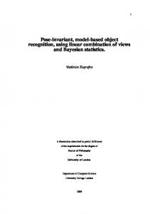
As shown in Table 1, we compare Makar-IOT, KLT-IOT against Makar’s displacement model and KLT in time efficiency under different conditions, including normal image quality, noise, occlusion and illumination changes. In Table 1, from the contrast of Makar’s displacement model and MakarIOT, we can see that the proposed algorithm in this paper can speed up the
365
block-matching motion estimation process, due to its longer detection interval ∆ (the number of frames between consecutive detection frames) than Makar’s method. Taking OpenCV as an example, Figure 6 shows the relation between the accuracy and the detection interval ∆ in these two methods. The pose 18
Table 1: Comparison of Makar’s displacement model, Makar-IOT, KLT and KLT-IOT in average run-time per frame (ms, millisecond) on four video classes under conditions of normal image quality, noise, occlusion and illumination changes. (a). Under normal image quality in four video classes. Method
OpenCV
Barrywhite
Titanic
Polish
Makar’s displacement model
74
61
146
108
Makar-IOT
56
42
83
71
KLT
16
15
18
19
42
38
KLT-IOT 46 39 (b). Under noise in four video classes. Method
OpenCV
Barrywhite
Titanic
Polish
Makar’s displacement model
68
55
160
111
Makar-IOT
45
45
88
74
KLT
16
19
16
16
38
42
KLT-IOT 40 39 (c). Under occlusion in four video classes. Method
OpenCV
Barrywhite
Titanic
Polish
Makar’s displacement model
68
55
149
175
Makar-IOT
51
45
79
82
KLT
17
16
16
16
KLT-IOT 44 44 40 (d). Under illumination changes in four video classes.
41
Method
OpenCV
Barrywhite
Titanic
Polish
Makar’s displacement model
192
173
160
153
Makar-IOT
159
156
109
127
KLT
38
17
18
22
KLT-IOT
83
64
58
72
19
of an object is represented by a quadrilateral. The average error of the four 370
quadrilateral angles is used to evaluate the accuracy of the result. The errors of a displacement model aggravate obviously with the increase of ∆ especially under poor conditions, while the Makar-IOT has less changes in errors. It clearly shows that the accuracy of a displacement model with ∆ = 10 is lower than that of the Makar-IOT with ∆ = 30, which means that the developed
375
method can have longer ∆ without loosing accuracy. For the sake of obtaining reasonable solutions to be compared, we set ∆ = 5 for a displacement model, and ∆ = 30 for the proposed method in the experiments. Thanks to a longer Delta, our method reduces the frequency of applying the detection method and takes better advantage of the frame-by-frame tracking than the Makar’s
380
method, and thus reduces the time of the block-matching motion estimation process effectively. 0DNDU�,27�2SHQ&9
��
Ƹ � Ƹ ��
�� �� �� � QRUPDO�TXDOLW\
QRLVH
RFFOXVLRQ
LOOXPLQDWLRQ FKDQJHV
'LIIHUHQW�TXDOLW\�YLGHRV
$YHUDJH�HUURU�RI�IRXU�DQJOHV LQ�SL[HOV
$YHUDJH�HUURU�RI�IRXU�DQJOHV LQ�SL[HOV
0DNDU V�GLVSODFHPHQW�PRGHO�2SHQ&9 ��
�� �� ��
Ƹ �� Ƹ �� Ƹ ��
�� �� � QRUPDO�TXDOLW\
QRLVH
RFFOXVLRQ
LOOXPLQDWLRQ FKDQJHV
'LIIHUHQW�TXDOLW\�YLGHRV
�E
�D
Figure 6: Relation between the accuracy and the detection interval ∆ in two methods: Makar’s displacement model and the Makar-IOT under different video qualities of OpenCV sequences.
In addition, it is noted that when the video is of poor quality such as T itanic, or under poor conditions such as illumination changes, more tracking points are needed to ensure a correct result. Experiments show that the block-matching 385
method in motion estimation is more sensitive to the increase of the tracking points. The more points needed, the faster the speed decreases in the Makar’s displacement model. In this case, the speed improvement of our method is more obvious. 20
In Table 1, from the contrast of KLT and KLT-IOT, KLT-IOT runs a little 390
slower than KLT which is the fastest algorithm in the table. The reason is that KLT switches to the detection method only when the number of the tracking points is reduced to a certain degree, which makes it have the longest detection interval. In contrast, KLT-IOT adjusts the positions of the tracking points after the KLT method, and switches between the frame-by-frame tracking and
395
the detection according to the results, which makes it cost a little more time. Nevertheless, KLT-IOT is still fast and meets most timing requirements in the real-world. 4.2. Accuracy The accuracy of the four algorithms is compared based on the average dis-
400
tances between the correct quadrilateral angles calculated in advance and the experimental ones. The results are shown in Table 2. By comparing Makar’s displacement model and Makar-IOT, since the MakarIOT has longer detection interval, the average errors of frames in the Makar-IOT are slightly more than Makar’s displacement model. However, the gap is small
405
enough to be acceptable. It is worth mentioning that in the video sequences with poor quality, such as T itanic with noise, P olish and examples with illumination changes, the Makar-IOT performs better. The reason is that a frame with a poor result in a detection method may have a good result by the frameby-frame tracking. Since there might be a great difference between the pattern
410
frame and the current frame of poor image quality, the number of keypoints or matches obtained will be inadequate to construct a reliable estimation result in the detection method. In contrast, the frame-by-frame tracking exploits the correlations of the consecutive frames and looks for a more reliable match point around the keypoint in the previous frame, and obtains a better pose according
415
to the previous result. Especially when the frame is in the front of the detection interval, the result acquired is more reliable due to tiny accumulated errors. From the comparison of KLT and KLT-IOT, KLT-IOT is better than KLT in accuracy, especially under the condition of illumination changes. KLT applies 21
Table 2: Comparison of Makar’s displacement model, Makar-IOT, KLT and KLT-IOT in average error distance of the pose quadrilateral angles on four video classes under conditions of normal image quality, noise, occlusion and illumination changes. (a). Under normal image quality in four video classes. Method
OpenCV
Barrywhite
Titanic
Polish
Makar’s displacement model
3
5
8
6
Makar-IOT
4
5
10
4
KLT
5
9
6
5
4
5
KLT-IOT 2 6 (b). Under noise in four video classes. Method
OpenCV
Barrywhite
Titanic
Polish
Makar’s displacement model
6
7
27
4
Makar-IOT
6
9
11
5
KLT
9
7
7
6
4
4
KLT-IOT 3 5 (c). Under occlusion in four video classes. Method
OpenCV
Barrywhite
Titanic
Polish
Makar’s displacement model
5
7
9
7
Makar-IOT
7
8
10
5
KLT
7
16
8
7
KLT-IOT 4 6 4 (d). Under illumination changes in four video classes.
5
Method
OpenCV
Barrywhite
Titanic
Polish
Makar’s displacement model
17
15
11
16
Makar-IOT
8
6
13
9
KLT
22
18
20
25
KLT-IOT
6
7
10
8
22
the number of the tracking points to represent the quality of the results, which 420
is too simply and unreasonable. Our method applies a deviation score model instead, and has more accurate results. A deviation score of a frame is computed as the distance of V T and V H in the frame-by-frame tracking (the score in the detection method is set to 0 so as to distinguish the detection method from the frame-by-frame tracking method).
425
A score can be used to effectively decide whether the frame satisfies the quality requirement. To evaluate the effectiveness of the deviation score model, we compare the scores with the errors of pose results obtained by a detection method. The errors effectively show the quality differences between the frames in a sequence. Figure 7 illustrates the comparisons under normal image qual-
430
ity in four video classes, where the scores are normalized for comparison. In OpenCV and T itanic examples, there are several high peaks in the curves of errors with detection, which means that the frames in these positions become fuzzy obviously. The curves of scores in the Makar-IOT and KLT-IOT methods are in agreement with the curves of errors in the detection method. Benefit
435
from the score model, the proposed method is able to switch to a detection method when the frame-by-frame tracking fails on these frames. Conversely, in Barrywhite and P olish examples, the curves of errors obtained by detection are relatively flat, and the values are under 20, which means that there are no significant differences in quality between frames. Accordingly, the scores are under
440
0.4 with uniform value distribution. In this case, the frame-by-frame tracking process will be continued without interruption until the number of consecutive tracking frames reaches the previously defined ∆ value that we set. The above results show that a frame can be captured by its deviation score when its quality changes sharply, and thus confirm that the score model can be used as a
445
criterion when switching from a frame-by-frame tracking to a detection.
23
2SHQ&9
2SHQ&9
$YHUDJH�HUURU�RI IRXU�DQJOHV�LQ SL[HOV
�
6FRUH
��� ��� ��� ��� � �
��� ��� ��� �� �
� �� �� �� �� �� �� �� �� �� �� �� �� �� �� �� �� �� �� )UDPH�QXPEHU 0DNDU�,27
./7�,27
�
�
'HWHFWLRQ
�D
%DUU\ZKLWH
%DUU\ZKLWH
$YHUDJH�HUURU�RI IRXU�DQJOHV�LQ SL[HOV
�
6FRUH
��� ��� ��� ���
�� �� �� �� �� � �
�
� �
�
��
��
��
��
��
��
��
��
��
�� �� �� �� �� �� �� �� �� �� �� �� �� �� �� �� �� �� )UDPH�QXPEHU
��
��
��
��
��
��
��
��
�� �� �� �� �� �� �� �� �� �� �� �� �� �� �� �� �� �� )UDPH�QXPEHU
��
'HWHFWLRQ
)UDPH�QXPEHU
�E 0DNDU�,27
./7�,27
7LWDQLF
7LWDQLF
$YHUDJH�HUURU�RI IRXU�DQJOHV�LQ SL[HOV
�
6FRUH
��� ��� ��� ��� � �
��� ��� ��� �� � �
� �� �� �� �� �� �� �� �� �� �� �� �� �� �� �� �� �� �� )UDPH�QXPEHU
0DNDU�,27
./7�,27
'HWHFWLRQ
3ROLVK
3ROLVK
$YHUDJH�HUURU�RI IRXU�DQJOHV�LQ SL[HOV
6FRUH
��� ��� ��� ��� �
�� �� �� �� �� � �
� �� �� �� �� �� �� �� �� �� �� �� �� �� �� �� �� �� �� )UDPH�QXPEHU 0DNDU�,27
�� �� �� �� �� �� �� �� �� �� �� �� �� �� �� �� �� �� )UDPH�QXPEHU
�F
�
�
�
� �� �� �� �� �� �� �� �� �� �� �� �� �� �� �� �� �� �� )UDPH�QXPEHU 'HWHFWLRQ
./7�,27 �G
Figure 7: Relation of the deviation scores in the proposed approaches and the errors of frames obtained by the detection method under normal image quality in four video classes.
24
5. Conclusion This paper proposes a real-time and reliable framework for the rigid object tracking and pose estimation. Since the proportion of valid points is an important factor to prolong the detection interval, we offer an iterative optimization 450
tracking method, in which, the locations of deviated points are iteratively adjusted and those invalid points with a great difference from the previous frame are discarded by a probabilistic voting model. Moreover, to evaluate the results of pose estimation, an adaptive detection interval is proposed, which can automatically switch the tracking mode between the detection method and the
455
frame-by-frame tracking method according to the quality of a frame. The developed algorithm can be combined with some inter-frame tracking schemes as an independent part, which improves the trade-off between the speed and accuracy of the system. The experimental results manifest the effectiveness of the proposed method. For the future work, we intend to improve the computational
460
efficiency by using binary features instead of floating-point features to shorten the detection and extraction time, and apply some Heuristic methods of learning during tracking to handle more complex real-world problems like greatly affine changes, significant clusters and outliers in the mobile environment.
References 465
[1] M. Aly, M. Munich, P. Perona, Bag of words for large scale object recognition, computational vision lab, Caltech, Pasadena, CA, USA, 2011. [2] D. Thachasongtham, T. Yoshida, F. de Sorbier, H. Saito, 3d object pose estimation using viewpoint generative learning, in: Image Analysis, Springer, 2013, pp. 512–521.
470
[3] A. Bosch, A. Zisserman, X. Munoz, Image classification using random forests and ferns, in: Computer Vision (ICCV), 2007 IEEE 11th International Conference on, IEEE, 2007, pp. 1–8.
25
[4] D. G. Lowe, Distinctive image features from scale-invariant keypoints, International journal of computer vision 60 (2) (2004) 91–110. 475
[5] H. Bay, A. Ess, T. Tuytelaars, L. Van Gool, Speeded-up robust features (surf), Computer vision and image understanding 110 (3) (2008) 346–359. [6] Y. Ke, R. Sukthankar, Pca-sift: A more distinctive representation for local image descriptors, in: Computer Vision and Pattern Recognition (CVPR), 2004 IEEE Computer Society Conference on, Vol. 2, IEEE, 2004, pp. II–
480
506. [7] K. Mikolajczyk, C. Schmid, A performance evaluation of local descriptors, IEEE Transactions on Pattern Analysis & Machine Intelligence 27 (10) (2005) 1615–1630. URL http://lear.inrialpes.fr/pubs/2005/MS05
485
[8] G. Takacs, V. Chandrasekhar, S. Tsai, D. Chen, R. Grzeszczuk, B. Girod, Unified real-time tracking and recognition with rotation-invariant fast features, in: Computer Vision and Pattern Recognition (CVPR), 2010 IEEE Conference on, IEEE, 2010, pp. 934–941. [9] S. Hinterstoisser, S. Benhimane, N. Navab, P. Fua, V. Lepetit, Online
490
learning of patch perspective rectification for efficient object detection, in: Computer Vision and Pattern Recognition (CVPR), 2008 IEEE Conference on, IEEE, 2008, pp. 1–8. [10] C. Zach, A. Penate-Sanchez, M.-T. Pham, A dynamic programming approach for fast and robust object pose recognition from range images, in:
495
Computer Vision and Pattern Recognition (CVPR), 2015 IEEE Conference on, IEEE, 2015, pp. 196–203. [11] A. Tejani, D. Tang, R. Kouskouridas, T.-K. Kim, Latent-class hough forests for 3d object detection and pose estimation, in: Computer Vision–ECCV 2014, Springer, 2014, pp. 462–477.
26
500
[12] E. Brachmann, A. Krull, F. Michel, S. Gumhold, J. Shotton, C. Rother, Learning 6d object pose estimation using 3d object coordinates, in: Computer Vision–ECCV 2014, Springer, 2014, pp. 536–551. [13] K. Pauwels, L. Rubio, J. Diaz, E. Ros, Real-time model-based rigid object pose estimation and tracking combining dense and sparse visual cues, in:
505
Computer Vision and Pattern Recognition (CVPR), 2013 IEEE Conference on, IEEE, 2013, pp. 2347–2354. [14] K. Pauwels, L. Rubio, E. Ros, Real-time model-based articulated object pose detection and tracking with variable rigidity constraints, in: Computer Vision and Pattern Recognition (CVPR), 2014 IEEE Conference on, IEEE,
510
2014, pp. 3994–4001. [15] K. A. Acharya, R. V. Babu, S. S. Vadhiyar, A real-time implementation of sift using gpu, Journal of Real-Time Image Processing (2014) 1–11. [16] D.-N. Ta, W.-C. Chen, N. Gelfand, K. Pulli, Surftrac: Efficient tracking and continuous object recognition using local feature descriptors, in: Computer
515
Vision and Pattern Recognition (CVPR), 2009 IEEE Conference on, IEEE, 2009, pp. 2937–2944. [17] F. Xiao, Y. J. Lee, Track and segment: An iterative unsupervised approach for video object proposals, in: Computer Vision and Pattern Recognition (CVPR), 2016 IEEE Conference on, Vol. 5, IEEE, 2016, pp. 9.
520
[18] J. Mooser, S. You, U. Neumann, Real-time object tracking for augmented reality combining graph cuts and optical flow, in: Proceedings of the 2007 6th IEEE and ACM International Symposium on Mixed and Augmented Reality, IEEE Computer Society, 2007, pp. 1–8. [19] J. Mooser, Q. Wang, S. You, U. Neumann, Fast simultaneous tracking and
525
recognition using incremental keypoint matching, in: Int’l Symp. on 3D Data Processing, Visualization and Transmission, 2008.
27
[20] M. Makar, S. S. Tsai, V. Chandrasekhar, D. Chen, B. Girod, Interframe coding of canonical patches for mobile augmented reality, in: Multimedia (ISM), 2012 IEEE International Symposium on, IEEE, 2012, pp. 50–57. 530
[21] M. Makar, S. S. Tsai, V. Chandrasekhar, D. Chen, B. Girod, Interframe coding of canonical patches for low bit-rate mobile augmented reality, International Journal of Semantic Computing 7 (01) (2013) 5–24. [22] B. K. P. Horn, B. G. Schunck, Determining optical flow, Artificial Intelligence 17 (1981) 185–203.
535
[23] B. D. Lucas, T. Kanade, et al., An iterative image registration technique with an application to stereo vision, in: IJCAI, Vol. 81, 1981, pp. 674–679. [24] J.-Y. Bouguet, Pyramidal implementation of the affine lucas kanade feature tracker description of the algorithm, Intel Corporation 5 (1-10) (2001) 4. [25] T. Muller, C. Rabe, J. Rannacher, U. Franke, R. Mester, Illumination-
540
robust dense optical flow using census signatures, in: Joint Pattern Recognition Symposium, Springer Berlin Heidelberg, 2011, pp. 236–245. [26] S. Ali, C. Daul, E. Galbrun, Illumination invariant optical flow using neighborhood descriptors, Computer Vision and Image Understanding 145 (2016) 95–110.
545
[27] D. T. Rosenbaum, D. Zoran, Y. Weiss, Learning the local statistics of optical flow, in: Advances in Neural Information Processing Systems, 2013, pp. 2373–2381. [28] D. Sun, S. Roth, J. P. Lewis, M. J. Black, Learning optical flow, in: Computer Vision–ECCV 2008, Springer, 2008, pp. 83–97.
550
[29] M. J. Black, Y. Yacoob, A. D. Jepson, Learning parameterized models of image motion, in: Computer Vision and Pattern Recognition (CVPR), 1997 IEEE Conference on, IEEE, 1997, pp. 561–567.
28
[30] H. Nam, B. Han, Learning multi-domain convolutional neural networks for visual tracking, arXiv preprint arXiv:1510.07945, 2015. 555
[31] R. Tao, E. Gavves, A. W. Smeulders, Siamese instance search for tracking, arXiv preprint arXiv:1605.05863, 2016. [32] A. Dosovitskiy, P. Fischery, E. Ilg, P. Hausser, C. Hazirbas, V. Golkov, P. V. Der Smagt, D. Cremers, T. Brox, Flownet: Learning optical flow with convolutional networks, arXiv preprint arXiv:1504.06852, 2015.
560
[33] A. Zheng, Y. Yuan, S. P. Jaiswal, O. C. Au, Motion estimation via hierarchical block matching and graph cut, in: Image Processing (ICIP), 2015 IEEE International Conference on, IEEE, 2015, pp. 4371–4375. [34] M. Pal, An optimized block matching algorithm for motion estimation using logical image, in: Computing, Communication & Automation (ICCCA),
565
2015 International Conference on, IEEE, 2015, pp. 1138–1142. [35] Y. M. Chi, T. D. Tran, R. Etienne-Cummings, Optical flow approximation of sub-pixel accurate block matching for video coding, in: Speech and Signal Processing (ICASSP), 2007 IEEE International Conference on Acoustics, Vol. 1, IEEE, 2007, pp. I–1017.
570
[36] C. Yan, Y. Zhang, J. Xu, F. Dai, J. Zhang, Q. Dai, F. Wu, Efficient parallel framework for hevc motion estimation on many-core processors, IEEE Transactions on Circuits and Systems for Video Technology 24 (12) (2014) 2077–2089. [37] C. Yan, Y. Zhang, F. Dai, X. Wang, L. Li, Q. Dai, Parallel deblocking filter
575
for hevc on many-core processor, Electronics Letters 50 (5) (2014) 367–368. [38] C. Yan, Y. Zhang, F. Dai, J. Zhang, L. Li, Q. Dai, Efficient parallel hevc intra-prediction on many-core processor, Electronics Letters 50 (11) (2014) 805–806.
29
[39] C. Yan, Y. Zhang, F. Dai, L. Li, Highly parallel framework for hevc mo580
tion estimation on many-core platform, in: Data Compression Conference (DCC), 2013, IEEE, 2013, pp. 63–72. [40] M. Cho, K. M. Lee, Progressive graph matching: Making a move of graphs via probabilistic voting, in: Computer Vision and Pattern Recognition (CVPR), 2012 IEEE Conference on, IEEE, 2012, pp. 398–405.
585
[41] H.-Y. Chen, Y.-Y. Lin, B.-Y. Chen, Robust feature matching with alternate hough and inverted hough transforms, in: Computer Vision and Pattern Recognition (CVPR), 2013 IEEE Conference on, IEEE, 2013, pp. 2762– 2769.
30
Iterative Optimization for Frame-by-frame Object Pose Tracking Highlights:
An iterative optimization tracking method is proposed to adjust the locations of deviated tracking points for longer detection interval. A probabilistic voting model is provided to determine whether a tracking point should be discarded or retained for more accurate pose estimation results. A deviation score model is proposed to determine the time to stop the frame-by-frame tracking process and relocate the tracking points by a detection method. The proposed framework is an independent part that can be combined with some inter-frame tracking algorithms for optimization. Experimental results manifest that the proposed framework can improve the trade-off between the speed and accuracy of the systems.