from single-images and of the pose estimation techniques. The application of ... developed in the context of the Marine Autonomous Robotics ... nition based on sonar array cameras and multi-frequency ... perception special attention must be paid to algorithmic ... segmentation results [18] since it better represents the human.
Object Detection and Pose Estimation Algorithms for Underwater Manipulation Fabjan Kallasi1 and Fabio Oleari1 and Marco Bottioni1 and Dario Lodi Rizzini1 and Stefano Caselli1 Abstract— In this paper, we describe object detection algorithms designed for underwater environments, where the quality of acquired images is affected by the peculiar light propagation. We propose an object detection method operating as a pipeline in which each phase works at a different level of abstraction. After a preprocessing phase, the input image is segmented into clusters according to the extracted features and each cluster is classified by exploiting the specific object properties. Finally, object pose estimation is performed by comparing the object model and the 3D point cloud obtained from stereo processing applied to the region found in the previous step. The algorithms have been tested on a dataset acquired using an embedded prototype stereo vision system consisting of commodity sensors. In spite of the poor quality of the stereo reconstruction, the dataset has allowed the evaluation of the object detection algorithms in underwater environment from single-images and of the pose estimation techniques. The application of the proposed object detection methods in object manipulation tasks has been also evaluated with experiments in a laboratory setup. Index Terms— Underwater imaging, Image segmentation, Stereo vision, Object detection.
I. I NTRODUCTION In recent years, the interest of the scientific community for underwater computer vision has increased taking advantage from the evolution in sensor technology and image processing algorithms. The main challenges of underwater perception are due to the higher device costs, the complex setup, and the distortion in signals and light propagation introduced by the water medium. In particular, light propagation in underwater environments suffers from phenomena such as absorption and scattering which strongly affect visual perception. This paper describes algorithms for object detection and pose estimation in underwater environments with stereo-vision perception. The algorithms have been developed in the context of the Marine Autonomous Robotics for InterventionS project (MARIS, Italian National Project). The MARIS project aims at developing a coordinated multiAUV (Autonomous Underwater Vehicle) system able to execute generic intervention, search-and-rescue and scientific tasks in underwater environments [4]. The proposed suite of algorithms is designed to operate in four steps. The first two steps aim at detecting the target object in single images through image enhancement 1 Authors are with RIMLab - Robotics and Intelligent Machines Laboratory, Dipartimento di Ingegneria dell’Informazione, University of Parma, Italy, {kallasi, oleari, bottioni, dlr,
caselli}@ce.unipr.it This work has been carried out in the frame of the MARIS project (PRIN, Italian National Project, contract n. 2010-FBLHRJ-007).
and feature-based segmentation. The resulting image segmentation produces a Region of Interest (ROI) that may represent or at least contain an object. Several approaches for ROI generation have been investigated adopting different assumptions on the target object. The third step uses the stereo image pair, combined with the generated ROI, to obtain a point-cloud representing the target in the scene w.r.t. the stereo vision frame. The final phase performs a geometric alignment between a model of the target object and the obtained point-cloud to estimate the object pose. Several algorithms, including bio-inspired approaches, have been exploited for object pose estimation. Evaluation of the algorithms has been based on a dataset generated with a low-cost embedded stereo vision system developed as initial prototype of the MARIS vision system [15]. The paper is organized as follows. Section II reviews the state of the art in object detection for underwater environments. Section III describes the image processing pipeline. Section IV reports the results on object detection and pose estimation in underwater environments and the results of object localization in a laboratory setup. Section V provides some final remarks and observations. II. R ELATED W ORK Computer vision is a major perception modality in robotics. In underwater environments, however, vision is not as widely used due to the problems arising with light transmission in water. Instead, sonar sensing is largely used as robust perception modality for localization and scene reconstruction in underwater environment. In [19] Yu et al. describe a 3D sonar imaging system used for object recognition based on sonar array cameras and multi-frequency acoustic signals emissions. An extensive survey on ultrasonic underwater technologies and artificial vision is presented in [10]. Underwater laser scanners guarantee accurate acquisition [8]; however, they are very expensive and are also affected by problems with light transmission in water. Computer vision provides information at lower cost and with higher acquisition rate compared to acoustic perception. Artificial vision applications in underwater environments include detection and tracking of submerged artifacts [13], seabed mapping with image mosaicing [14], and underwater SLAM [6]. Kim et al. [11] present a vision-based object detection method based on template matching and tracking for underwater robots using artificial objects. Garcia et al. [7] compare popular feature descriptors extracted from underwater images with high turbidity. Stereo vision systems have been only recently introduced in underwater
applications due to the difficulty of calibration and the computational performance required by stereo processing. To improve homologous point matching performance, QueirozNeto et al. [17] introduce a stereo matching system specific for underwater environments. Disparity of stereo images can be exploited to generate 3D models, as shown in [2], [3]. Leone et al. [12] present a 3D reconstruction method for an asynchronous stereo vision system. III. A LGORITHMS Vision-based object detection may be addressed by different techniques according to the input data: through image processing of an image acquired by a single camera or through more complex shape matching algorithms based on stereo processing. The algorithm pipeline for underwater object detection proposed in this paper consists of several phases (fig. 1), each operating at decreasing level of abstraction and under different assumptions. The initial step aims at detecting salient regions w.r.t. the background representing candidate objects, possibly with no prior knowledge about the object. The final pose estimation, instead, requires a detailed geometric description of the target object. Furthermore, the first two phases operate on a single image to detect the object, whereas the two final phases process stereo images to obtain the object pose. In our evaluation, the target to be detected has cylindrical shape and can be represented by a geometric parametric model. This assumption is exploited only in the later phases of the pipeline.
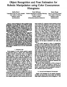
Fig. 2. An underwater image before (left) and after (right) the application of contrast mask and CLAHE.
perception special attention must be paid to algorithmic solutions improving image quality. The first phase of the algorithmic pipeline in Figure 1 is designed to compensate the color distortion due to the light propagation in water through image enhancement. No information about the object is used in this phase since the processing is applied to the whole image. Popular techniques for image enhancement are based on color restoration [1]. The approach adopted in this paper focuses on strengthening contrast to recover the blurry underwater images. A contrast mask method is first applied to the component L of CIELAB color space of the input image. In particular, the component Lin,i of each pixel i is extracted, a median filter is applied to the L-channel of the image to obtain a new blurred value Lblur,i , and the new value is computed as Lout,i = 1.5 Lin,i − 0.5 Lblur,i . The effect of the contrast mask is a sharpened image with increased contrast. Next, in order to re-distribute luminance, a contrast-limited adaptive histogram equalization (CLAHE) [16] is performed. The combined application of contrast mask and CLAHE compensates the light attenuation and removes some of the artifacts in the image. Figure 2 shows an example of the effect of pre-processing for an underwater image. In our experiments, the image enhanced by CLAHE alone is not discernible from the one obtained after applying both filters. Hence, the contrast mask may not be required, thereby reducing processing time. B. Mono-Camera Processing
Fig. 1.
Algorithm pipeline for object detection and pose estimation.
A. Image Pre-Processing Underwater object detection requires the vision system to cope with the difficult underwater light conditions. In particular, light attenuation produces blurred images with limited contrast, and light back-scattering results into artifacts in acquired images. Object detection becomes even more difficult in presence of suspended particles or with an irregular and variable background. Hence, for underwater
Processing of individual images is performed on the image stream produced by one of the cameras and aims at detecting the region of the image that contains the target object. This phase provides several advantages. First, identification of a ROI restricts the search region of the target object in later processing stages and therefore prevents detection errors in later, more expensive steps. Second, since object recognition on a 3D point cloud is computationally expensive, monocamera processing helps in decreasing the requested overall computation time. Third, based on the amount of prior knowledge, in some cases the object can be accurately detected in a single image, although the estimation of its pose remains rather difficult. This phase of the algorithm pipeline, therefore, operates to detect a ROI that may represent or at least contain an object. The ROI may be searched according to different
criteria based on a specific feature of the object to be found. We have developed three approaches that exploit different assumptions on the properties of the target. The HSV (Hue Saturation Value) color space is used to improve the color segmentation results [18] since it better represents the human color perception. In particular, to quantize the total color level a color reduction is performed on the H channel of the input image. The method described in this paper uses 16 levels of quantized color. The first segmentation method is based on the assumption that the unknown object never occupies more than a given portion of image pixels and has a uniform color. The input image is partitioned into subsets of (possibly not connected) pixels with the same hue level according to the value of reduced channel H. The rough level quantization is not affected by the patterns generated by light back-scattering. The region corresponding to a given hue level is estimated as the convex hull of the pixels. Only regions whose area is less than 50% of the image are selected as part of the ROIarea . This heuristic rule rests on the hypothesis that the object is observed from a distance such that only the background occupies a large portion of the image. ROI estimation only exploits the relative color uniformity of a texture-less object, but it does not identify a specific object. This approach tends to overestimate the area that potentially contains the object. The second approach exploits the information on the target color. When the object color is known, a more specific color mask (ROIcolor ) can be applied to detect the object with an accurate estimation of object contour. Hence, the ROIcolor is obtained composing the regions where color is close (up to a threshold) to the target color. The third method is based on target shape. Detection of object shape requires an accurate image segmentation that cannot be achieved through color. Indeed, a feature vector can be associated to each pixel in order to better partition the image. A vector of two features, the value of channel H and the gradient response to Sobel, is used to cluster with a K-means algorithm [5] and to label the corresponding pixels. The feature vector can be expanded to include other features in the future. Each pixel is labeled according to the Euclidean metric in the feature space. The goal of the clustering algorithm is to label each pixel as part of either an object or the background according to its feature vector. Thus, the result of this step is to partition the image into connected regions, each with a uniform label. The method can potentially distinguish more than one object from the background if the two features are salient w.r.t. the background. In our application, the ROIshape is obtained by matching each cluster-region to a projected cylinder. In particular, since the cluster-region representing the target shape is unknown, external contours for each cluster are obtained. Each closed contour represents a cluster-region, and shape matching between the contours and the target shape allows identification of the target region. Since this work is focused on the detection of cylindrical object, parallel lines effectively approximate the contour of a projected cylindrical shape.
Under this assumption, the target region is recognized by detecting the two longest parallel segments in the shape. These segments are obtained using the Hough Transform of each contours. The longest parallel lines are computed with a cumulative histogram of the line angle w.r.t. the image origin. One of the two cluster-regions is classified as the target object if the pixel number is close to the area of the rotated rectangle generated with the parallel line angle. In contrast to the other two approaches (ROIarea and ROIcolor ), this method is able to detect whether the target object belongs to the image before performing pose estimation. An example of ROI generated by the second phase is shown in figure 3.
Fig. 3.
Mask generation example.
In general, object pose estimation cannot be performed on a single image and requires 3D perception. However, if the object shape is known, as in our case, pose estimation is possible also with a monocular camera. In particular, a cylinder is defined once the cylinder radius cr and its axis, a line with equation c(t) = cp +cd t, are given. The contour of a cylinder in the image plane is delimited by two lines with equations liT u = 0 with i = 1, 2, where u = [ux , uy , 1]T is the pixel coordinate vector and l1 , l2 are the coefficients. Let l0 be the parameters of the line representing the projection of the cylinder axis in the image. The two lines with parameters l1 and l2 are the projections on the image plane of the two planes, which are tangent to the cylinder and contain the camera origin. The line with parameter l0 is the projection of the plane passing through the cylinder axis and the camera origin. The equations of these three planes in the 3D space are given by liT (Kp) = (K T li )T p = nTi p = 0
(1)
where K is the camera matrix obtained from the intrinsic calibration, ni = K T li the normal vectors of the planes corresponding to the lines li with i = 0, 1, 2 (in the following, the normalized normals n ˆ i = ni /kni k are used), and p a generic point in camera reference frame coordinates. The direction of the cylinder axis is given by direction vector cd = n ˆ1 × n ˆ 2 . If the cylinder radius cr is known, then the distance of the cylinder axis from the camera center is d=
sin
cr 1 acos (|ˆ n1 2
� ·n ˆ 2 |)
(2)
The projection of the camera origin on the cylinder axis is equal to cp = d(cd × n ˆ 0 ) (if cp,z < 0, then substitute cp ← −cp ). These geometric constraints allow estimation of the object pose in space using only a single image. The accuracy of such estimation depends on the image resolution
and on the extraction of the two lines. It can be used as an initial estimation or as a validation criterion of the object pose computed on the 3D point cloud generated from stereo vision. C. Stereo-Camera Processing The generated ROI is used as a filtering mask in the third phase to generate a lighter point-cloud that represents the 3D scene limited to the object. This filtering permits to estimate the pose of the object, with no need for further detection, in the final phase. The benefit of restricting the region size where stereo processing is performed is limited when the disparity image is computed using incremental block-matching SAD (sum of absolute differences) algorithm. Since the SAD of a block is computed using the SAD values of adjacent blocks, the advantage of computing the disparity image only on the ROI is reduced. Indeed, estimation of point clouds limited to the ROI saves about 15% of the time for each frame. D. Pose estimation The final phase of the pipeline uses the geometric information of the target object to estimate the pose w.r.t. the stereo vision frame. The importance of a ROI is more apparent in object recognition, since this step requires computationally expensive operations on point clouds. In particular, the ROI can be used to select the point cloud C where to search objects. In our investigation the objects to be recognized have a cylindrical shape and can be represented by a parametric model. In particular, we represent cylinders using 7 parameters: the three coordinates of a cylinder axis point cp = [cp,x , cp,y , cp,z ]T , the axis direction vector cd = [cd,x , cd,y , cd,z ]T , and the radius cr . The model matching algorithm simultaneously searches for a subset of the point cloud that better fits a cylindrical shape and computes the value of the cylinder parameters c = [cTp , cTd , cr ]T . For pose estimation three algorithms have been applied: • PSO: Particle Swarm Optimization. Bio-inspired global optimization algorithm based on the movement of individuals swarms. • DE: Differential Evolution. Bio-inspired global optimization algorithm based on the evolution of a set of individuals. • RANSAC: RANdom SAmple Consensus. Model fitting algorithm. The pose estimation is obtained through geometric alignment of the model of the searched object and the point cloud obtained from stereo processing. These algorithms require a fitness function that measures the consensus of a subset of the point cloud C over a candidate model c. A natural fitness function is the percentage of points pi ∈ C such that their distance to the cylinder c is less than a given threshold dthr . The more obvious measure of the displacement between a point pi and a cylinder c is the Euclidean distance kcp × (cp − pi )k − r dE (pi , c) = kld k
(3)
However, the Euclidean distance may not take into account some orientation inconsistencies. If the normal vector ni on
Fig. 4. An example of pose estimation by matching the raw point cloud (orange) and a cylinder model (blue).
point pi can be estimated, the angular displacement between the normal and the projection vector of the point pi on the cylinder c (called proj(pi , c) henceafter) provides dN (pi , ni , c)
=
αi
=
proj(pi , c)
=
min(αi , π − αi ) � � ni · proj(pi , c) arcos kni k kproj(pi , c)k � � pi · cd − cp · cd pi − c p − cd kcd k2
(4)
The chosen distance function is a weighted sum of two distances d(pi , ni , c) = w · dE (pi , c) + (1 − w) · dN (pi , ni , c)
(5)
Figure 4 shows an example where the cylinder pose is approximately recovered from the point cloud. It should be observed that the cylinder model parameters and the point-tomodel distance are the only parts of the algorithm depending on the specific object shape. IV. E XPERIMENTAL E VALUATION A. Underwater Image Processing An underwater dataset adopted for the experimental evaluation of the algorithm suite has been acquired using a stereo vision system consisting of non-synchronized C270 Logictech webcams in a sealed waterproof transparent canister [15]. The image dataset has been acquired at the Lake of Garda (Italy) in two distinct experimental sessions, each comprising multiple ambient situations and different objects (Fig. 5). The dataset includes images with several submerged cylindrical objects at depth ranges from 1.8m to 3m. In both sessions the average depth of the camera was about 40cm below water surface. The image pre-processing algorithms discussed in section III-A significantly influence underwater object detection performance. In order to assess the effectiveness of the preprocessing algorithms, the ROIcolor and the ROIarea have been computed on a set of 304 sample images. Results have been computed on both the raw and the pre-processed images. The average percentage of ROIcolor and ROIarea pixels over the whole image and the ratio between the two quantities are reported in Table I. The region found by the ROIcolor only slightly depends upon the quality of the input image (since it exploits the information about the color of the object), whereas the computed ROIarea is more affected by the image quality. The ROIarea in the pre-processed image
Frame number TP TN FP FN Precision Recall Accuracy 1-FPRate F-Measure
Gray target 304 522 417 63 37 91.9% 98.8% 92.0% 64.0% 95.2%
Orange target 443 248 153 29 13 89.5% 95.0% 90.5% 84.1% 92.2%
Total 965 665 216 66 18 91.0% 97.4% 91.3% 76.6% 94.1%
TABLE II S HAPE BASED SEGMENTATION PERFORMANCE . Fig. 5.
Images of the experimental sessions.
Fig. 6. Example of ROI (left) and CMask (right) computed on the same input frame.
is on average only one third of the ROIarea computed in the raw image. Thus, assuming that the ROIcolor reasonably approximates the ground truth, the ROIarea provides an adequate estimate of the object for underwater detection as long as appropriate pre-processing is performed. Figure 6 shows an example of ROIarea and ROIcolor computed on the same input frame. The complete mono-camera processing is performed on average, on a current platform, in 74.82 ms, with a standard deviation of 3.20 ms. Pre-processing no yes
Frames 304 304
ROIcolor 9.32% 9.07%
ROIarea 33.18% 11.98%
ROIarea ROIcolor
3.72 1.31
in these experiments. Mono-camera images have been used to estimate the pose of a cylindrical pipe, as discussed in section III-B. The algorithm computes all the parameters of the cylinder axis that allow localization of the target object. However, during experiments at the Garda lake, the embedded system swung rather fast attached to the floating support, due to the continuous waves and close to surface operations (see Figure 5). In such experiments no groundtruth is usually available, therefore a parameter invariant to camera motion is required to assess the precision of the proposed method. The object lies on the lake floor and the camera depth remains approximately constant. Thus, the distance between the camera center and the cylinder axis in equation (2) approximately meets this pre-requisite. Table III illustrates the average distance and the standard deviation of the axis computed in a sequence of 302 frames. The standard deviation of 17 cm is due to both the estimation error of the algorithm and the slight variation of distance caused by waves. Num. Frames 302
Avg. Distance [mm] 1441
Std.Dev. Distance [mm] 169
TABLE III M ONO - CAMERA ESTIMATED DISTANCE .
TABLE I ROIarea AND ROIcolor COMPUTATION W. R . T. IMAGE PRE - PROCESSING .
The third mono-processing method presented in section III-A is somewhat different than the area/color based segmentation. This algorithm, besides the subset pixel representing the target object, also detects whether the image contains the target. An evaluation of the effectiveness of the shape-based ROI generation has performed on a set of 965 frames including two kinds of color for the cylindrical object (orange and gray) and images with or without the target object. Table II illustrates the performance of shape based segmentation. The values of precision, recall and accuracy are above 90% for this method. The execution time of segmentation and recognition algorithms is on average 149.6 ms with a standard deviation of 11.3 ms (Intel R Core i7-3770 CPU 3.40GHz, 8 GB RAM). We expect to improve this performance by using a customized clustering algorithm instead of the generic general purpose implementation used
A second set of experiments has aimed at assessing the object detection and pose estimation performance on the point cloud acquired in the stereo camera configuration. Unfortunately, the point clouds obtained from the underwater dataset turned out to be rather sparse and noisy. As mentioned above, in water the embedded system was attached to a floating support, and the camera baseline swang due to waves. Since the webcams are not synchronized by a hardware trigger, the computed disparity image turned out to be noisy and inaccurate. Thus, an alternative dataset of images has been acquired in air to obtain an evaluation of the full stereo-processing pipeline. In this alternative setting, the target cylindrical pipes were placed in a dry river bed among sand and stones, and the embedded acquisition box was manually moved. Figure 7 summarizes the object recognition results for RANSAC, PSO, and DE recognition algorithms. The three algorithms obtain comparatively similar but unsatisfactory recognition results. As could be
eye-in-hand camera provides a perceptual feedback, since the stereo camera may be occluded by the manipulator itself.
Object Recognition Performance 100
RANSAC PSO DE
percentage
80
Mean St.Dev.
60
TABLE IV M EAN VALUE AND STANDARD DEVIATION OF EYE - IN - HAND CAMERA POSE W. R . T. THE ROBOT WRIST FRAME ( ORIENTATION AS QUATERNION ).
40
20
0
re su
ea m
F-
cy ra
u cc
A
l
l ca
Re
n sio
i ec
Pr
Fig. 7.
x (mm) y (mm) z (mm) qx × 103 qy × 103 qz × 103 10.46 -47.95 194.08 18.89 1.36 -0.39 0.22 1.61 3.44 0.52 0.66 1.33
Object recognition results on the point cloud.
Stereo Cameras
Eye-in-hand Camera
Target Object
Fig. 8. The laboratory protototype used to experiment object detection and approaching. The axes of the target object cˆx , cˆy and cˆz , the stereo camera optical axis sˆz and the axes of the desired viewpoint frame for the eye-in-hand vˆx , vˆy and vˆz are also shown.
expected, RANSAC is at least one order of magnitude faster than the alternative algorithms. Additional investigation is required to obtain reliable 3D perception in complex underwater or outdoor scenes. Although methods for asynchronous stereo vision processing [12] could be used, we will include synchronized camera acquisition in our next stereo vision system prototype. B. Application Scenario The proposed algorithms have been designed to operate with a specific underwater perception and manipulation system, which consists of a manipulator, a stereo camera, and an eye-in-hand camera placed in the hand of the manipulator [4]. In the main application scenario, the target object is detected by processing an image acquired by one of the two cameras and its pose is estimated from the point cloud obtained from stereo vision processing. Then, the robot approaches the detected object and grasps it using the gripper in the end-effector of the manipulator. During this operation
The execution of this task is an important test-bed for the proposed object detection algorithms and for the analysis of occlusions. Unfortunately, a complete underwater system will not be available until the final phases of the MARIS UAV construction. We have therefore decided to develop a laboratory prototype to study visibility conditions and the issues arising in the cooperation between sensing and actuation, although without the specific features of the underwater environment. Figure 8 illustrates the system developed at RIMLab, which consists of a Comau Smart Six manipulator equipped with a Schunk PG70 gripper, a Logitec C270 camera pair for stereo processing and another eye-inhand Logitec C270. Since an item is detected w.r.t. sensor reference frames, the estimation of the relative sensor poses is required to correctly operate with objects. The calibration of the eye-in-hand camera is performed using the method described in [9], which compares the relative motion of the manipulator wrist frame and the corresponding motion of the camera frame. The sensor egomotion is estimated using a known checkerboard marker. Table IV illustrates the mean value and standard deviation of the camera pose parameters computed on 20 trials. The orientation parameters are expressed in unitary quaternion form. Although the groundtruth is not available, these results show that the estimated values are rather stable. The eye-in-hand pose w.r.t. to the robot base frame is computed using the manipulator state data. The pose of the stereo camera has been estimated using a checkerboard marker used as a common reference with the eye-in-hand camera. Mean St.Dev.
∆θ (deg) 2.09 1.71
TABLE V M EAN VALUE AND STANDARD DEVIATION OF CYLINDER OBJECT AXIS W. R . T. THE EYE - IN - HAND CAMERA .
The described setup has been used to test the accuracy of target object pose estimation. Of course, the observation conditions of the laboratory are rather different from underwater environment, but such results represents a bound on the achievable accuracy of the proposed detection and localization algorithms. If the object pose provided by the stereo camera is accurate enough, then a viewpoint focused on the target object can be computed for the eye-in-hand camera. The main hypothesis is that the manipulator can
on a dataset obtained in outdoor, in-air conditions. Several approaches have been investigated for object pose recovery from the 3D point cloud and for further classification of objects. The accuracy of object pose estimation has been assessed in a laboratory setup that simulates an application scenario. Although the laboratory operating conditions are rather different from underwater environment, object localization is sufficiently accurate for the execution of grasping tasks. Fig. 9. Target cylindrical object observed from the eye-in-hand camera. The alignment angular error ∆θ is the angle between the cylinder axis (dashed blue line) and image axis (dashed black line).
move in a relatively free space without risking collisions. In particular, we assume that the manipulator can approach the object from the direction of stereo camera optical axis sˆz . Let cˆx , cˆy and cˆz be the axes of cylindrical target object frame computed by the stereo image w.r.t. the robot base frame. The cˆz axis corresponds to the symmetry axis of cylinder. The axes of eye-in-hand camera desired viewpoint are computed as vˆx = vˆy × vˆz vˆy = m ˆz vˆz = sˆz −
sˆz · cˆz kˆ sz kkˆ cz k
The eye-in-hand camera optical axis vˆz is computed through the orthonormalization of stereo camera direction sˆz on cylinder axis cˆz . The choice of vˆy aligns image plane with the symmetry axis of the cylindrical object. Thus, the angle ∆θ between cylinder axis and image axis can be used as a measure of the accuracy of object pose estimation. Figure 9 illustrates the image observed from the eye-in-hand camera and the corresponding alignment angular error. Table V illustrates the mean value and standard deviation of ∆θ on 15 trials. The orientation error is on average about 2◦ and is rather negligible in the execution of grasping tasks. V. C ONCLUSIONS This paper has presented an algorithm suite, consisting of several steps, for underwater object detection and recognition, and its experimental evaluation in real underwater environment. Suitable preprocessing and image enhancement algorithms have proven effective in improving underwater images, thereby enabling detection of regions of interest as well as detection and localization of known objects in sequential image streams gathered from a single camera. Three techniques for the detection of the ROI containing the target object have been compared. The shape-based detection algorithm is able to correctly detect objects in a single image with precision and accuracy both above 90%. The 3D point clouds obtained from stereo processing of multiple underwater camera streams have not allowed reliable object detection and localization due to the very noisy dataset. The stereo processing pipeline has been eventually evaluated
R EFERENCES [1] C. Ancuti, C.O. Ancuti, T. Haber, and P. Bekaert. Enhancing underwater images and videos by fusion. In IEEE Conference on Computer Vision and Pattern Recognition (CVPR), pages 81–88, 2012. [2] V. Brandou, A-G Allais, M. Perrier, E. Malis, P. Rives, J. Sarrazin, and P-M Sarradin. 3D reconstruction of natural underwater scenes using the stereovision system iris. In OCEANS 2007 - Europe, pages 1–6, 2007. [3] R. Campos, R. Garcia, and T. Nicosevici. Surface reconstruction methods for the recovery of 3D models from underwater interest areas. In OCEANS, 2011 IEEE - Spain, pages 1–10, 2011. [4] G. Casalino, M. Caccia, A. Caiti, G. Antonelli, G. Indiveri, C. Melchiorri, and S. Caselli. Maris: a national project on marine robotics for interventions. 22nd Mediterranean Conference on Control and Automation, 2014. [5] R.O. Duda, P. E Hart, and D.G. Stork. Pattern classification. John Wiley & Sons, 2012. [6] R. Eustice, H. Singh, J. Leonard, M. Walter, and R. Ballard. Visually navigating the rms titanic with slam information filters. In Proceedings of Robotics: Science and Systems, Cambridge, USA, June 2005. [7] R. Garcia and N. Gracias. Detection of interest points in turbid underwater images. In IEEE OCEANS, pages 1–9, 2011. [8] Alan Gordon. Use of laser scanning system on mobile underwater platforms. In Proc. Sym. on Autonomous Underwater Vehicle Technology (AUV), pages 202–205, 1992. [9] R. Horaud and F. Dornaika. Hand-eye calibration. 14(3):195–210, 1995. [10] P. Jonsson, I. Sillitoe, B. Dushaw, J. Nystuen, and J. Heltne. Observing using sound and light: a short review of underwater acoustic and videobased methods. Ocean Science Discussions, 6(1):819–870, 2009. [11] Donghoon Kim, Donghwa Lee, Hyun Myung, and Hyun-Tak Choi. Object detection and tracking for autonomous underwater robots using weighted template matching. In OCEANS, 2012 - Yeosu, pages 1–5, 2012. [12] A. Leone, G. Diraco, and C. Distante. Stereoscopic system for 3d seabed mosaic reconstruction. In Proc. of the IEEE Int. Conf. on Image Processing (ICIP), pages 541–544, 2007. [13] M. Narimani, S. Nazem, and M. Loueipour. Robotics vision-based system for an underwater pipeline and cable tracker. In OCEANS 2009 - EUROPE, pages 1–6, 2009. [14] Tudor Nicosevici, Nuno Gracias, Shahriar Negahdaripour, and Rafael Garcia. Efficient three-dimensional scene modeling and mosaicing. Journal of Field Robotics, 26(10), 2009. [15] F. Oleari, F. Kallasi, D. Lodi Rizzini, J. Aleotti, and S. Caselli. Performance evaluation of a low-cost stereo vision system for underwater object detection. World Congress of the International Federation of Automatic Control, 2014. [16] S. M. Pizer, E. P. Amburn, J. D. Austin, R. Cromartie, A. Geselowitz, T. Greer, B. T. H. Romeny, and J. B. Zimmerman. Adaptive histogram equalization and its variations. Computer Vision, Graphics, Image Processing, 39(3):355–368, September 1987. [17] J.P. Queiroz-Neto, R. Carceroni, W. Barros, and M. Campos. Underwater stereo. In Computer Graphics and Image Processing, 2004. Proceedings. 17th Brazilian Symposium on, pages 170–177, 2004. [18] S. Sural, G. Qian, and S. Pramanik. Segmentation and histogram generation using the HSV color space for image retrieval. In International Conference on Image Processing., volume 2, pages II–589–II– 592 vol.2, 2002. [19] Son-Cheol Yu, Tae-Won Kim, A. Asada, S. Weatherwax, B. Collins, and Junku Yuh. Development of high-resolution acoustic camera based real-time object recognition system by using autonomous underwater vehicles. In OCEANS 2006, pages 1–6, 2006.