was introduced by the IST BroadWay project, IST-2001-32686). The off-loading is possible using CANA but certain changes in the standard HiperLAN/2 protocol ...
INTERNATIONAL WORKSHOP ON WIRELESS AD-HOC NETWORKS (IWWAN) 2004
1
Layered Architecture and Modules of CANA Supporting Dual Mode HiperLAN/2 Konstantinos Oikonomou1, Konstantinos Ntagkounakis1, Athanasios Vaios2, Nikolaos Zinelis2, Ioannis Stavrakakis2 1
2
INTRACOM S.A, Emerging Technologies & Markets Department, Athens, Greece Email:{okon, knta}@intracom.gr
University of Athens, Department of Informatics & Telecommunications, Athens, Greece Email:{avaios, grad0654, ioannis}@di.uoa.gr
AP
Abstract—The Centralized Ad-hoc Network Architecture (CANA) is an efficient way to support dual mode systems, [1]. A dual mode of operation has been introduced in the traditional 5 GHz HiperLAN/2 to allow data off-loading by using resources of an ad-hoc network created at 60 GHz (the dual mode concept was introduced by the IST BroadWay project, IST-2001-32686). The off-loading is possible using CANA but certain changes in the standard HiperLAN/2 protocol stack are required and certain algorithms need to be incorporated. In this paper, the new enhanced protocol stack of HiperLAN/2 that supports CANA is presented as well as key algorithms that need to be developed and whose performance is crucial for the efficient utilization of the system resources. These algorithms can also be implemented for any other WLAN in order to support a second mode of operation. Simulations shed light into the trade-offs induced by the dual mode of operation and the way the network resources may efficiently be utilized under certain conditions. Index Terms—Layered Architecture, CANA, Ad-Hoc, Dual Mode, HiperLAN/2
M
I. INTRODUCTION
ODERN multimedia network applications require increased data rates, especially in case of high traffic needs and number of users (i.e. hotspots). Existing WLAN technologies like IEEE 802.11, [2], or HiperLAN/2, [3], provide a fair coverage range but suffer from data rate limitations (i.e. wireless medium) and cannot satisfy the needs of hotspot areas. To increase capacity, the Centralized Ad-hoc Network Architecture (CANA) has been introduced, [1]. CANA incorporates ad-hoc characteristics in the standard HiperLAN/2 operation and allows for the support of high data rates in highly dense areas based on a dual mode of operation (i.e. the standard mode at 5 GHz and the ad-hoc mode at 60 GHz), [4]. The main reason for using the 60 GHz mode of operation is that at least 3 GHz of spectrum are available form 59 GHz to 62 GHz. Channels with 80 MHz of bandwidth can be used to support data rates up to 160 Mbps at the physical layer, [4].
CH
CH CH FN
CH CH
CH
FN
CH
FN
AP
Access Point
5 GHz Range
CH
Cluster Head
60 GHz Range
FN
Forwarding Node
5 GHz Data Flow
Mobile Terminal
60 GHz Data Flow
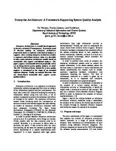
Fig. 1: A snapshot of CANA
CANA’s primary aim is to offload the 5 GHz band by using resources from the 60 GHz band. A specific set of MTs that are closely located and want to exchange data, create an adhoc network in the form of a cluster of MTs that operate in the 60 GHz mode of operation for a certain number of frames. An MT can use now both the 5 GHz and the 60 GHz mode of operation; the former is similar to the standard, [3], while the latter introduces three different roles: a) Clusterhead (CH); b) Forwarding Node (FN); c) MT in the 60 GHz mode of operation, [1]. The CH creates the frame at 60 GHz and its role is in general similar to the role of the AP for the 5 GHz mode of operation. The role of the FN is to forward data packets among adjacent clusters while the role of the MT at 60 GHz is similar to the role of the MT at 5 GHz. A snapshot of a network that employs CANA is shown in Fig. 1. Certain algorithms should be incorporated to support CANA. The Neighborhood Discovery (ND) algorithm, [5], is required in order to identify the neighborhood of each MT, the Neighborhood Discovery Initiator (NDI) that decides when it is necessary to start a new ND phase and the Broadway Routing (BWR) that decides on cluster creation and the routing
INTERNATIONAL WORKSHOP ON WIRELESS AD-HOC NETWORKS (IWWAN) 2004 information. It is evident that in order to implement the corresponded algorithms and realize CANA, certain changes in the standard protocol stack of HiperLAN/2 should take place resulting to a new layered architecture, [1]. The purpose of this paper is to present the layered architecture in Section II and analyze in detail the key algorithms and show important performance issues and trade-offs in Section III. Simulation results are presented in Section IV and the conclusions are drawn in Section V. II. LAYERED ARCHITECTURE
Access Point Cluster Specific Information
MH
prtpr messages
CH_R_table
Ethernet
CH_C_table
CANA-SSCS NDI
Next ND Phase
MAC_ID_table
FN_table
BWR
C_table MTi_table
BWRR_table
ND_table
MFL
NDP
RN FL_table
CANA-DLC ND
AP_table
ND messages
Control Plane
Mobile Terminal NCE
Cluster Specific Information
MH
prtpr messages
Ethernet
CH_R_table CH_C_table
CANA-SSCS Next ND Phase
CANA-DLC
The first step towards CANA realization is to enhance the existing HiperLAN/2 protocol stack, [3], by introducing certain new modules and algorithms to be included for the fine system operation. The particular layers that need to be enhanced are the Data Link Control (DLC) layer, which will be referred to as CANA-DLC, and the Service Specific Convergence Sublayer (SSCS), which will be referred to as CANA-SSCS. Additionally, a new entity (represented as a layer) is added for the efficient peer-to-peer (prtpr) communication between nodes considering that Ethernet is the upper layer. This entity is called the Node Communication Entity (NCE) and it can be seen in Fig. 2. NCE
2
User Plane
Fig. 2: HiperLAN/2 Enhanced Layered Architecture for CANA support and Information Flow (AP case).
Fig. 2 depicts the enhanced protocol stack for the AP case. The MT case is a simplified version of it as it may be seen in Fig. 3. NCE’s role is to exchange control information between the AP and the MTs through prtpr messages. This information is forwarded through the User Plane, [6]. The corresponding module is named Message Handler (MH) and is located in NCE (Control Plane). The modules in the figures are represented as ellipses, the tables that contain information are represented as rectangulars and the depicted arrows correspond to the information flow between modules. Messages between different devices are represented with large arrows (prtpr messages and ND messages).
ND
MTi_table
Control Plane
ND messages
User Plane
Fig. 3: HiperLAN/2 Enhanced Layered Architecture for CANA support and Information Flow (MT case).
The modules and their input/output are the following: 1) Neighborhood Discovery (ND): discovers the connectivity between nodes at 60 GHz, output: AP_table (MTi_table for each of the MTs); 2) Monitor Flows (MFL): monitoring of the resources for a data session, input: MAC_ID_table, output: FL_table; 3) Resource Needs (RN): estimation of the resources for a data session, input: FL_table, output: BWRR_table; 4) Neighborhood Discovery Processing (NDP): merging of ND information, input: AP_table plus MTi_tables, output: ND_table; 5) Neighborhood Discovery Initiator (NDI): decides on the next ND phase, input ND_table, output: Next ND Phase; 6) BroadWay Routing (BWR): cluster and routing information, input: ND_table and BWRR_table, output: C_table, FN_table; 7) Message Handler (MH): responsible to send/receive information to the MTs, input: C_table and FN_table, output: CH_C_table, CH_R_table, Cluster Specific Information and prtpr messages. All the aforementioned modules are required for the system operation but three of them, (ND, NDI and BWR), are of special interest since the behavior of the corresponding implemented algorithms greatly affects the system performance. For example, the ND should provide an accurate view of the ad-hoc network topology at 60 GHz and it should not last too many frames in order not to waste network resources. Frequent ND phases, when are not needed, do allow for a successful off-loading and it is NDI’s responsibility to avoid this. Finally, BWR has to efficiently create the clusters, distribute the CHs and the FNs roles, and decide on cluster lifetime. III. ALGORITHMS FOR CANA SUPPORT A detailed description of the three most crucial algorithms (ND, NDI and BWR) is presented in this section focusing on these particular parts of the algorithms that affect the system performance. A. ND The ND process provides information about the ad-hoc topology to the AP by discovering the directly reachable
INTERNATIONAL WORKSHOP ON WIRELESS AD-HOC NETWORKS (IWWAN) 2004 neighbors (i.e. one-hop away) of all MTs inside the cell and measuring the quality of the corresponding links. Every MT and the AP participate in a ND phase by exchanging hello messages and maintain neighborhood information in the form of a list containing the neighbors and the status of the corresponding links [5]. This information is sent to the AP, which is responsible for the path selection. The AP decides a ND phase should be performed. It may be done periodically or be event-driven based on several criteria such as: the available bandwidth at the centralized frequency, the density of users inside the cell, the number of new users in the system, the detected link breakages at the ad-hoc frequency and the elapsed time since the last ND phase. The AP sends a broadcast message to inform all MTs inside its coverage area, indicating the frequency channel that is used for the ND phase, the time instant at which this procedure is initiated and potentially the transmission schedule of the hello messages. The MTs and the AP exchange hello messages based on their MAC IDs, in order to determine their one-hop away neighbors and construct their link state tables. After receiving its neighbors’ hello messages, each MT can determine the state of each one-hop away link by estimating the signal-tonoise ratio provided by the physical layer. Depending on the estimated link state, different transmission rates (and communication levels) may be achieved. At the end, the MTs forward the collected information (MTi_table) to the AP. B. NDI For the NDI case it is assumed that the decision regarding when a new ND phase should start is taken immediately after the current ND phase and the “Next ND Phase” message seen in Fig. 2 and Fig. 3 is sent immediately after. Suppose that a ND phase has just been completed and f old is the number of frames since the previous ND phase. The objective is to identify the number of frames f new after which a new ND phase should take place. Let the ND_table, which was calculated during the last ND phase, be denoted by NDnew , whereas the ND_table, which was calculated during
the previous ND phase, be denoted as NDold . Let ∆{X } be that matrix operation that derives the number of non-zero elements of table X . It is clear that f new is influenced by f old and
∆{NDnew − NDold }. If ∆{NDnew − NDold } is rather small
(below a certain threshold threshold A ) then the number of frames until the new ND phase may be increased. If ∆{NDnew − NDold } is rather high (above a certain threshold
threshold A ≥ threshold B ) then the number of frames until the new ND phase may be reduced. For those values of ∆{NDnew − NDold } that are between the two thresholds the number of frames until the next ND phase may remain the
3
same.
If ∆{ND new − NDold } ≤ threshold A then
f new = f old + drift .
If threshold A < ∆{ND new − ND old } ≤ threshold B then
f new = f old .
If ∆{ND new − ND old } > threshold B then
f new = f old − drift .
Fig. 4: The NDI Algorithm.
The algorithm presented in Fig. 4 describes the basic structure of the NDI algorithm. Parameter drift is a positive natural number. It is clear that a large number of changes in the topology requires frequent ND phases whereas few changes require less frequent executions of ND. It is obvious that for appropriate values of the thresholds and the parameter drift , this algorithm is able to avoid hazardous situations (i.e. frequent ND phases when mobility is small or rare ND phases when mobility is high). C. BWR The BWR algorithm is responsible to identify the traffic needs, assert link availability and create routes for the reliable exchange of traffic through the 60 GHz channels. The BWR is considered as the heart of a system employing CANA and it is critical for the overall system performance improvement. Successful off-loading can significantly increase the total capacity of the system; however, there is always a corresponding cost concerning the switching of several MTs to the 60 GHz band to create a cluster. During the cluster lifetime, the switched MTs may lack access to several MTs (i.e. those still operating at 5 GHz and those in isolated clusters) or the core network, which may result in receiving/transmitting delayed data and have a major impact on certain delay-sensitive applications. Another factor that affects the performance of BWR is the confidence in the operation of the 60 GHz links given their high dependency on MT mobility. If a broken link situation occurs in the path from the source to the destination (i.e. during cluster operation) the off-loading operation is cancelled and data remain in the source or the CH in order to be forwarded later through HiperLAN/2 standard operation; delay is again introduced. It is reasonable to assume that the ND algorithm provides accurate information for the ad-hoc network topology when it is completed. However, as time passes, the probability that the topology has changed due to mobility increases. To minimize the probability of a BWR decision failure due to mobility, the BWR is executed immediately after a ND phase. The basic steps of the BWR operation are presented in the flow chart seen in Fig. 5. When initiated, the BWR accesses the FL_table (see Fig. 2) to identify a pair of MTs that exchange a significant amount of data worthy to be served
INTERNATIONAL WORKSHOP ON WIRELESS AD-HOC NETWORKS (IWWAN) 2004 through a 60 GHz link in order to off-load the 5 GHz mode of operation. BWR starts the first loop by identifying and processing the pair with the highest traffic demands as it appears in the FL_table, continues with the next pair and stops when all source-destination combinations are processed. START
Select a pair of MTs with heavy traffic exchange.
x-hop link neighbors at 60Ghz ? x < threshold
NO
NO
YES
Do the source, destination, or intermediate-hops have traffic obligations to other MTs ?
YES
Do the MTs satisfy the requirements to participate in the cluster ?
NO YES • Distribute CH, FN Roles and notify the Participating MTs • Update AP’s Routing Tables (notify for the absence of the MTs)
NO
End of pairs YES STOP
Fig. 5: The BWR Algorithm.
The next step is to access the ND_table to identify if there is a path between the source and the destination in the 60 GHz network topology. As the number of hops increases, the path becomes more vulnerable to mobility changes and this is the reason why the BWR only considers paths up to a certain number of hops. If no route can be found, the BWR proceeds to the next pair. In case a path is available, the BWR is trying to identify whether there exist any other traffic flows between both the source and the destination MTs and other MTs operating at the 5 GHz mode. If any of them has traffic flows to other MTs, then these flows should be interrupted when they switch to a 60 GHz channel. In this case, the BWR asserts the possibility that those MTs can be incorporated in the 60 GHz cluster as well (in a similar BWR process). If this is not possible, the BWR resumes and proceeds to another candidate pair. If there are no traffic flows to other MTs, the BWR creates the clusters and distributes the CH, FN and CN roles to the participant MTs. Each cluster’s lifetime is selected, in this case, to be long. However, it should always be smaller than the interval until the next ND process ( f new ). When the cluster is created, the participant MTs are notified and provided all relevant information through prtpr messages, while the AP notifies its MAC functions not to allocate resources at 5 GHz for the participant MTs during the
4
cluster’s lifetime. For the case of the AP’s 60 GHz cluster, the AP updates its routing information. If there are data flows with small traffic requirements to other MTs, another strategy is to create a cluster with very short lifetime that will be periodically activated until the next ND phase. In this manner, off-loading may occur in data sessions, while traffic flows to HiperLAN/2 associated MTs can be preserved. According to the BWR operation described above, two are the key parameters that affect the CANA performance. The first is mobility, which may result in broken link situations during the 60 GHz mode of operation. One way to reduce the significance of mobility is to select shorter cluster lifetimes; however, in this case the off-loading gains will be exploited for a shorter time. A more complex approach is to monitor the topology changes, through the ND phase, and use this information to optimize the BWR decision process. When mobility is high, the BWR can be applied with more strict criteria. Such a criterion would be to restrict the length of the 60 GHz paths to single-hop paths only. The second parameter corresponds to the traffic conditions. If the nature of the data traffic is highly bursty, then the BWR may decide on cluster creation based on high traffic demands and during the cluster operation the traffic demands may become smaller (for example an application that stops running). In this case, the traffic burstyness (if known) can be used as a criterion to select a shorter cluster lifetime. Another important issue arises when the data flow from a particular MT changes destinations frequently. If this is the case, a cluster may be erroneously created based on a particular data flow, which may not exist during the cluster operation. To deal with traffic issues, periodic cluster activations, as described above, are required to be adopted to the particular environment. Alternatively, the MTs that experience traffic burstyness or flow changes may be excluded from the BWR process if their behavior is hazardous for the system performance. IV. SIMULATION RESULTS The ND process constitutes the main control overhead for CANA since it requires that the system remains inactive until it is completed and for this reason it should be carefully executed. On the other hand, this process needs to be repeated frequently as it provides useful information for the establishment of ad hoc paths. Clearly, there is a trade-off here that needs to be considered carefully. To address all the above issues taking into consideration the potential spatial reuse and higher capacity induced by multihop paths, a cell of 100mX100m with 50 moving MTs has been modelled in ns-2, [7]. Simulations were run for 300 seconds. The results were averaged over 5 runs for each scenario. Estimations of the length of the required hello messages and link state tables were also made. Four different levels ℓ of short-range communication have been defined and
INTERNATIONAL WORKSHOP ON WIRELESS AD-HOC NETWORKS (IWWAN) 2004
Speed: 3m/sec 6m
8m
12m
15m
Level: 6m 7,0% 6,0% ND Overhead
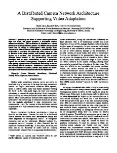
considered inside a cell based on the physical distance (in meters) between the MTs; ℓ Є {6, 8, 12, 15}. Two MTs that are d meters apart can establish a level ℓ communication as long as 0.8ℓ ≤ d ≤ 1.2ℓ. A sequence of n MTs each of which is away from the preceding MT by some distance in (0.8ℓ, 1.2ℓ) is said to form a level ℓ path of length (n-1) hops. In Fig. 6 and Fig. 7, the dependence of the overhead of the ND process on the number of hops that constitute a path, the number of MTs inside the cell, the different communication levels and mobility, is shown. Pause time of 0 seconds has been considered to illustrate more dynamic environments induced by the propagation characteristics of 60 GHz. The ND process overhead is defined as the fraction of time during which the ND process is performed (including the required switching time to the frequency channel of the ND process, [1]). The number of MTs inside a cell affects the ND process overhead since it affects its duration. We assume that the ND process is periodically performed with such a period that more than 90% of the possible paths do not break between two consecutive ND phases for the specific speed and communication level. Note that the ND phase determines the one-hop neighborhood of a MT but the BWR uses multihop paths and their “lifetime” is crucial (their lifetime decreases as the mobility and the link error rate increase).
5
1m/sec
5,0% 4,0%
3m/sec
3,0% 2,0% 1,0% 0,0%
10m/sec
5m/sec 15m/sec 20m/sec 25
50
75
100
125
150
175
200
Number of MTs in a cell
Fig. 7: ND overhead of four-hop paths of level 6m versus the number of MTs inside a cell (for different MT speeds)
V. CONCLUSIONS In this paper the layered architecture that supports CANA is presented and the focus is primarily on those modules (and the corresponding implemented algorithms) whose performance is essential not only for CANA support but also for the efficient utilization of the network resources. Three key algorithms have been presented in detail and the corresponding key issues have been identified and explained. The performance of CANA is strongly affected by the credibility of the information provided by the Neighborhood Discovery process. Simulations have shown that the overhead of such process depends on the lifetime of the shorter-range, multihop paths employed, which, at the same time, provide the means for off-loading the 5 GHz band.
ND Overhead
2,5% 2,0%
ACKNOWLEDGMENT
1,5% 1,0% 0,5% 0,0% 1
2
3
4
Number of hops
Fig. 6: ND overhead versus the number of hops constituting a path (200 users)
In general, if the BWR requires large paths then frequent ND phases are required and more overheads have to be paid in order to maintain 90% of the paths existing. Although the lifetime of multi-hop paths is low, a large amount of information can be sent over them, since the 60 GHz frequency band can support very high bit rates. To establish these high transmission rate paths, CANA needs to update the ND information. The periodicity of the ND process is adjusted (so is the induced overhead) according to the supported communication level (transmission rate) and mobility. In hotspots, where traffic needs are high and the number of users is increased, there is always the need for extra capacity. It is shown that even in the worst case, the ND overhead to support short-range paths that provide high bit rates does not exceed 7%. Consequently, the BWR algorithm decides between the off-loading capability of shorter-range, multi-hop paths and the increased induced ND overhead based on the traffic needs. In addition, the effect of the different roles employed at the MTs when operating at 60 GHz should be taken into account to make efficient routing decisions.
The BroadWay project (IST-2001-32686) is partly funded by the Commission of the European Community. The partners involved in the project are the Motorola Labs France, TNO-FEL Netherlands, Intracom and the National & Kapodistrian University of Athens, Greece, IMST, IRK and Dresden University of Technology, Germany and FARRAN, Ireland. REFERENCES [1]
[2] [3] [4]
[5]
[6]
[7]
Konstantinos Oikonomou, Athanasios Vaios, Sebastien Simoens, Pietro Pellati, Ioannis Stavrakakis, "A Centralized Ad-Hoc Network Architecture (CANA) Based on Enhanced HiperLAN/2", 14th IEEE International Symposium on Personal, Indoor and Mobile Radio Communications, PIMRC 2003, Beijing, China, September 7-10, 2003. "IEEE Standard for Wireless LAN-Medium Access Control and Physical Layer Specification", P802.11, Nov. 1997. M. Johnson, "Hiperlan/2 – The Broadband Radio Transmission Technology Operating in the 5 GHz Frequency Band", Available via the H/2 Global Forum, http://www.hiperlan2.com. M. de Courville, S. Zeisberg, Markus Muck, J. Schönthier, "BROADWAY – the Way to Broadband Access at 60 GHz", IST Mobile & Wireless Telecommunications Summit, Thessaloniki, Greece, June 2002. Athanasios Vaios, Konstantinos Oikonomou, Ioannis Stavrakakis, "A Centralized Routing Scheme Supporting Ad Hoc Networking in Dual Mode HIPERLAN/2", IST Mobile & Communications Summit 2003, Aveiro-Portugal, June 15-18, 2003. Konstantinos Oikonomou, Ioannis Tenidis and Ioannis Stavrakakis, "A Mechanism to Enable Differentiated Services QoS in HIPERPLAN/2", 8th IEEE International Conference on Telecommunications, Bucharest, Romania, June 2001. The Network Simulator ns-2, http://www.isi.edu/nsnam/ns/.