Sep 7, 2017 - document to the TMDL/WLA coordinators for distribution to the. States to use in conducting wasteload allocations. An earlier draft of Parts 3 and ...
United States Environmental Protection Agency
Office Of Water (WH-585)
EPA-823-R-92-005 August 1992 -
&EPA
Technical Guidance Manual For Performing Waste Load C&EE28 Allocations Book 111: Estuaries Part4’ Critical Review Of Coastal Embayment And Estuarine Waste Load Allocation Modeling
RecycledlRecyclable Printed on paperthat contains at least 50% recycled fiber
TECHNICAL GUIDANCE MANUAL FOR PERFORMING WASTE LOAD ALLOCATIONS
BOOK 111: ESTUARIES
PART 4:Critical Review of Coastal Embayment and Estuarine Waste Load Allocation Modeling
Project Officer Hiranmay Biswas, Ph.D. Edited By Robert B.Ambrose,Jr. P.E.' Prepared by Paul L. Freedman,P.E.2 David W.Dilks,Ph.D.* Bruce A. Monson'
1. Center for Exposure Assessment Modeling, Environmental Research Laboratory,US.EPA,Athens, G A 2. LTI, Limno-Tech,Inc.,Ann Arbor, MI
Prepared for
U.S.Environmental Protectjon Agency 401 M. Street,S.W. Washington,D.C.20460
Table of Contents Preface
. . . . . . . . . . . . . . . . . . . . . . . . . . . . . . . . . . . . . . . .
Acknowledgements
...................................
10. Great Lakes Embayment Seasonal Phytoplankton Model of Saginaw Bay
. . . .
10.1. Background . . . . . . . . . . . . . . . . . . . . . . . . . . . . . . . 10.2. Problem Setting . . . . . . . . . . . . . . . . . . . . . . . . . . . . . 10.3. Model Application . . . . . . . . . . . . . . . . . . . . . . . . . . . . 10.4. Post-Audit . . . . . . . . . . . . . . . . . . . . . . . . . . . . . . . . 10.5. References . . . . . . . . . . . . . . . . . . . . . . . . . . . . . . . . 1 1 . Potomac Estuary Water Quality Modeling
11.1. Background . . 1 1.2. Problem Setting
. . . . . . . . . . . . . . . . . . . .
v
vii 10-1 10-1 10-1 10-2 10-8 10-8 11-1
11-1 11-1 I 1.3. Dynamic Estuary Model (DEM)of Dissolved Oxygen . . . . . . . . . . 11-2 1 1.4. Potomac Eutrophication Model (PEM) . . . . . . . . . . . . . . . . . . 11-6 1 1.5. Finite Element Model . . . . . . . . . . . . . . . . . . . . . . . . . . . 1 1-13 1 1.6.References . . . . . . . . . . . . . . . . . . . . . . . . . . . . . . . . 1 1-1 8 . . . . . . . . . . . . . . . . . . . . . . . . . . . . . . . . . . . . . . . . . . . . . . . . . . . . . . . . . .
12.Manasquan Estuary Real Time Modeling
12.1. Background . . 12.2. Problem Setting
. . . . . . 12.3. Model Calibration . . 12.4. References . . . . . .
. . . .
13.Calcasieu River Estuary Modeling
. . . .
. . . . . . . . . . . . . . . . . . . . .
. . . . . . . . . . . . . . . . . . . . . . . .
12-1 12-1 12-2 12-11
. . . . . . . . . . . . . . . . . . . . . . . .
13-1
. . . .
. . . .
. . . .
. . . .
. . . .
. . . .
. . . .
. . . .
. . . .
. . . .
. . . .
. . . .
. . . .
. . . .
. . . .
. . . .
. . . .
. . . .
13.1. Background . . . 13.2. Problem Setting . 13.3. Model Application
13.4. 13.5.
. . . . . . . . . . . . . . . . . . . . . . . . . . . . . . . . . . . . . . . . . . . . . . . . . . . . . . . . . . . . . . . . . . . . . . . . . . . . . . . . . . . . Total Maximum Daily Loads . . . . . . . . . . . . . . . . . . . . . . . References . . . . . . . . . . . . . . . . . . . . . . . . . . . . . . . .
14.Expert Critique of Case Studies
12-1
. . . . . . . . . . . . . . . . . . . . . . . . . .
14.1. Robert V .Thomann.Ph.D. . . 14.2. Donald R.F. Harleman,Ph.D. 14.3 GeraldT. Orlob. Ph.D.,P.E. .
13-1 13-1 13-2 13-7 13-8 14-1
. . . . . . . . . . . . . . . . . . . . . . . . . . . . . . . . . . . . . . . . . . . .
14-1 14-10
. . . . . . . . . . . . . . . . . . . . . .
14-14
iii
Table of Contents Preface
........................................
Acknowledgements
. . . . . . . . . . . . . . . . . . . . . . . . . . . . . . . . . . .
10. Great Lakes Embayment Seasonal Phytoplankton Model of Saginaw Bay
. . . .
10.1. Background . . . . . . . . . . . . . . . . . . . . . . . . . . . . . . . 10.2. Problem Setting . . . . . . . . . . . . . . . . . . . . . . . . . . . . . 10.3. Model Application . . . . . . . . . . . . . . . . . . . . . . . . . . . . 10.4. Post-Audit . . . . . . . . . . . . . . . . . . . . . . . . . . . . . . . . 10.5. References . . . . . . . . . . . . . . . . . . . . . . . . . . . . . . . . 1 1 . Potomac Estuary Water Quality Modeling
. . . . . . . . . . . . . . . . . . . .
v vii
10-1
10-1 10-1 10-2 10-8 10-8
11-1
Background . . . . . . . . . . . . . . . . . . . . . . . . . . . . . . . 11-1 Problem Setting . . . . . . . . . . . . . . . . . . . . . . . . . . . . . 11-1 Dynamic Estuary Model (DEM)of Dissolved Oxygen . . . . . . . . . . 11-2 Potomac Eutrophication Model (PEM) . . . . . . . . . . . . . . . . . . 11-6 1 1.5. Finite Element Model . . . . . . . . . . . . . . . . . . . . . . . . . . . 1 1-13 1 1.6. References . . . . . . . . . . . . . . . . . . . . . . . . . . . . . . . . 1 1-18 11.1. 1 1.2. 1 1 .3. 1 1.4.
12.Manasquan Estuary Real Time Modeling
12.1. 12.2. 12.3. 12.4.
. . . . . . . . . . . . . . . . . . . . .
12-1
Background . . . . . . . . . . . . . . . . . . . . . . . . . . . . . . . 12-1 Problem Setting . . . . . . . . . . . . . . . . . . . . . . . . . . . . . 12-1 Model Calibration . . . . . . . . . . . . . . . . . . . . . . . . . . . . 12-2 References . . . . . . . . . . . . . . . . . . . . . . . . . . . . . . . . 12-11
13. Calcasieu River Estuary Modeling
. . . . . . . . . . . . . . . . . . . . . . . .
13.1. Background . . . . . . . . 13.2. Problem Setting . . . . . . 13.3. Model Application . . . . . 13.4. Total Maximum Daily Loads 13.5. References . . . . . . . . . 14. Expert Critique of Case Studies
13-1
. . . . . . . . . . . . . . . . . . . . . . . . . . . . . . . . . . . . . . . . . . . . . . . . . . . . . . . . . . . . . . . . . . . . .
13-1 13-1 13-2 13-7 13-8
. . . . . . . . . . . . . . . . . . . . . . . . . .
14-1
. . . . . . . . . . . . . . . . . . . . . . . . . . . . . . . . . . . . . . . . . . . . . .
14.1. Robert V .Thomann. Ph.D. . . 14.2. Donald R.F.Harlernan. Ph.D. 14.3 GeraldT.Orlob. Ph.D.,P.E. .
. . . . . . . . . . . . . . . . . . . . . . . . . . . . . . . . . . . . . . . . . . . . . . . . . . . . . . . . . . . . . . . . . .
iii
14-1 14-10 14-14
The document isthethird of a series of manuals providing information and guidance for the preparation of waste load allocations. The first documents provided general guidance for performing wasteload allocations (Book I), as well as guidance specifically directed toward streams and rivers (Book 1). This document provides technical information and guidance for the preparation of waste load allocations in estuaries.The document is divided into four parts:
range of representative geographic areas, freshwater bays and embayments, estuaries, and models. The studies were not selected because they were exemplary but rather because they represented applications of diverse approaches. Each of the studies has particular merits and deficiencies; the balance is different in each study. Perfect examples are not always the best teachers. By examing the strengths and weaknesses of each application the reader can appreciate howto best use the technical guidance and how to avoid misuse and c o m m o n problems.
Part 1 of this document provides technical information and policy guidance for the preparation of estuarine waste load allocations. It summarizes the important water quality problems, estuarine characterisitics and processes affecting those problems, and the simulation models available for addressing these problems. Part 2 provides a guide to monitoring and model calibration and testing, and a case study tutorial on simulation of waste load allocation problems in simplified estuarine systems.Part 3 summarizes initial dilution and mixing zone processes,available models, and their application in waste load allocation.
The examples are summarized with only limited commentary. The information for each is presented with sufficient detail to allow the reader to understand what was done and to highlight certain noteworthy aspects. Following the case examples,three experts critique the relative merits and deficiencies in each case study and provide their opinions on the proper approach to estuarine modeling. Adraft version of thisdocument received scientific peer review from the following modeling experts:
This part, “Part 4:Critical Review of Coastal Embayment and Estuarine Waste Load Allocation Modeling,” summarizes several historical case studies,with critical review by noted experts. The reader should refertothe preceding parts for information on model processes, available models, and guidance to monitoring and calibration.
Steven C.Chapra, University of Colorado-Boulder Donald R.F. Harleman, Massachusetts Institute of Technology
The technical guidance is comprehensiveand state-ofthe-art.Case studies of applications serve as the best teacher of the proper and improper use of this technical guidance. Similar models are often used in large freshwater coastal embayments and estuaries because there are s o m e similarities in their hydrodynamic transport processes.Therefore,included in this part are one freshwater embayment study and three estuarine studieswhere models were used for waste load allocation. These studies have been selected to provide a
Gerald T. Orlob, University of California-Davis Robert V. Thomann, Manhattan College Their comments have been incorporated into the final version.
Organization: “Technical Guidance Manual for Performing Waste Load Allocations. Book Ill: Estuaries”
2
3 4
-
uaries and Waste Load Allocation Models Application of Estuarine Waste Load Allocation Models Use of Mixing Zone Models in Estuarine Waste Load Allocation Modeling Critical Review ofCoastal Embayment and Estuarine Waste Load Allocation Modeling
V
R
UNITED STATES ENVIRONMENTAL PROTECllOPl AGENCY WASHINGTON,D.C. 20460
J U L 2 0 1992 OFFICE OF WATER
MEMORANDUM SUBJECT:
Final Technical Guidance Manual For Performing Wasteload and 4 Allocations: Book 111, E s t d d e s i Parts
,*
Q L y !5 ?----iW, I?
FROM:
Tudor T. Davies, Director Office of Science and Techndogy (WH-551)
TO :
Regional Water Management Division Directors Regional Environmental Services Division Directors Regional TMDL/WLA Coordinators
Attached, for national use, is the final version of the Technical Guidance Manuals for Performing Wasteload Allocations: Book 111, Estuaries, Parts 3 and 4. Parts 1 and 2 were finalized during FY 91 and have been in distribution ever since for national use. We are sending extra copies of Parts 3 and 4 of the guidance document to the TMDL/WLA coordinators for distribution to the States to use in conducting wasteload allocations.
An earlier draft of Parts 3 and 4 were reviewed by your staff and their comments were considered in finalizing this guidance. Major modifications to the earlier draft include: o
The discussion on mixing zone criteria in Part 3 (see page 7-3) is now consistent with the March 1991 version of the Technical Sumort Document for Water Oualitv-based Toxics Control.
0
The title of Part 4 has been modified from Critical Review of Estuarine Wasteload Allocation Modelinq to Critical Review of Coastal Embavment and Estuarine Wasteload Allocation Modelinq. This change was necessary because the Saginaw Bay example in Part 4 of this guidance does not meet the strict regulatory definition of an estuary,
If you have any questions or comments or desire additional information, please contact Russell S. Kinerson, Exposure Assessment Branch, Standards and Applied Science Division (WH-585), Telephone (202) 260-1330. Attachments
Frdd cn Recycled Paper
owledgements This document represents the efforts of several people and the integration of several documents. Site selection and national expert review were managed by Hiranmay Biswas, U.S. EPA Office of Science and Technology (formedy Monitoring and Data Support ivision). Chapter 12 on the Manasquan along with portions of Chapter 1 1 were excerpted from an earlier draft Technical Guidance Manual prepared by Richard Wagner, Jane Metcalfe, and Elizabeth Southerland of JRB Associates. Chapter 10 on Saginaw Bay was prepared by Bruce Monson,Chapter 1 1 by David Dilks, and Chapter 13 by Paul Freedman,all of Limno-Tech, !ne.Scott Hinz and Susan Johnson sf Limno-Tech are acknowledged for their work in editing this draft document. National expert peer review of this manual was provided by Robert V. Thomann, Manhattan College, Donald R.F. Harleman, Massachusetts Institute of Technology, and Steven C. Chapra, University of Colorado at Boulder. In addition, helpful internal review comments were received from Thomas Barnwell,U.S.EPA Athens Environmental Reasearch Laboratory; James Martin, Asci Corporation; Wick Brandes, U.S. EPA Office of ~ a s t e ~Enforcement ~ ~ @ ~ and Compliance; Steve Glomb, U.S.EPA Office of Wetlands, Oceans, and Watersheds; Dale Bryson, U.S.EPA Region V; Mimi Dannel, U.S.EPA Region VI; Aaron Setran, U.S.EPA falk,Texas Water Commission, i~ers~t~ of Southern Louisiana; tate of Hawaii. A significant part process was managed by Karen ffice of Science and Technology.
of ~ ~ was responsible ~ for ~ the of this document, and the final layout was done by Tad SBawecki,allso of Limns-Tech.
~
vii
~
e
c
~
IO.Great Lakes Embayment Seasonal Phytoplankton Model of Saginaw Bay 10.1.Background The Saginaw Bay is not an estuary. However, its hydrodynamic processesare similartothose observed in some shallow estuarieswith wind-drivencirculation. The SaginawBay phytoplankton model of Bierman and Dolan (1986a,b)is presented here to illustrate the application of a dynamic and kinetically complex box model to a Great Lakes embayment.This model was calibrated with two comprehensive data sets. Following significant reductions in loadings and changes in the Bay’s water quality, the model projections were tested and validated (post-audit)with another comprehensive data set.The model was developed as part of a long-termstudy of eutrophication in Saginaw Bay. It was designed as a management and research tool to estimate phytoplankton response to various phosphorus control strategies.The model was used exten-
sively by the USEPA and International Joint Commission to evaluate nutrient loading reductions for Saginaw Bay. The authors describe the model as “a deterministic, spatially segmented, multi-class phytoplankton model.” The phytoplankton comprise five functional groups: diatoms, greens, non-nitrogen-fixingbluegreens, nitrogen-fixing blue-greens,and ”others.” Nutrient uptake is considered for phosphorus, nitrogen,and silica. Herbivory,settling, and decomposition are mechanisms of phytoplankton depletion.
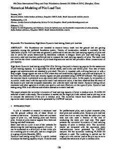
10.2.Problem Setting Located on the western shore ofLake Huron (Figure 10-1),the Saginaw Bay watershed is approximately 21,000km2(8108mi2).It is dominated by agriculture, forest,and four urban-industrialcenters:Bay City,Flint, Midland, and Saginaw. The 1980 population for the The area is drained area was slightly over 1,200,000. by the Bay’smajor tributary,the Saginaw River. The River accounts for 90 percent of the tributary inflow to the Bay. Saginaw Bay extends 90k m fromthe River’smouth to the Bay’sopening to Lake Huron. It is broad (42km), shallow (10 m average depth), and vertically wellmixed. The average hydraulic residence time is approximately four months. The Bay has been characterized as behaving like a simple estuary (Ayerset al,1956).Like estuaries,it is a nutrient-richarm of a larger nutrient-poorwater body, Lake Huron (Richardson,1974).Furthermore, water levels and flow directionsofthe Bay change.Unlike an estuary,the water level is influencedby wind patterns rather than tides.Northern gales can create a seiche in the Bay that raises the water level at the mouth of the Saginaw River by more than a meter (Fish and Wildlife Service,1956;cited by Richardson,1974).
r
0 0
.
SCALE .
20
10
,
3Orniles
IO 2.0 30 40 5 0 k m
Source: Bierman and D o h , 198
Figure 10-1. Saginaw Bay site m a p [Bierman and Dolan (1 986a). Reprinted from ASCE Journal of Environmental Engineering,Vol. 1 1 2,No. 2.p. 401 With permission]. I
The International Joint Commission identified Saginaw Bay as one of forty-twoGreat Lakes Areas of Concern needing remedialaction.Eutrophication ofthe Bay had caused taste, odor, and filter-clogging problems for municipal water supplies.Waste discharges and runoff have been major contributorsto water quality degradation. In the late 1970’s,phosphorus reduction programs were implemented at wastewater treatment plants and resulted in large reductions ofphosphorus loading to the Bay.From 1975to 1980the phosphorus loads were reduced over 65 percent.The model was
10-1
calibrated and verified when the phosphorus loadings were high (1974and 1975)and tested in a post-audit following the large reductions of phosphorus (1 980). LEG
10.3.Model Application Although this model’s development began in a more simple form,it is presented here in its most advanced form as a spatially segmented,temporally dynamic model. A more spatially simplified precursor model (Bierman and Dolan, 1980) provided some valuable conclusionsaboutthe biological and chemical processes in the waterbody. These findings were used to develop the kinetic structure and calibrate the more spatially detailed model. For example,the factors influencing phytoplankton dynamics in the model are temperature,light,nutrients,and zooplankton grazing. Temperature and light were generally more growthrate limitingthan nutrients.However,nutrient limitation became importantfor peak phytoplankton crops.In the spring and fall,the primary source of phosphorus was externalloading,which fed the dominant diatom crops. In mid-summer,the primary sourceof phosphoruswas recyclingwithin the water column and from sediments, which fed the summer blue-green crops. The multi-classphytoplankton model was developed to predict the response of the Saginaw Bay phytoplankton to various phosphorus control strategies.Of primary concern were the nuisance, bloom-forming blue-greensthat cause taste and odor problems. The emphasis in the model was on nutrient cycling since it is a limiting and controllable factor in phytoplankton growth. Several hypothetical scenarios and a postaudit are presented below following examination of the calibration and validation ofthe model.
103.1. Model Descriptibn The model developed for Saginaw Bay falls into a general class of models called “box models.” The approach involves dividing the water body into several cells (orboxes), each ofwhich isconsidered completely mixed (Figure 10-2).Transport of chemicals, biomass,and water between cell; occurs through advective transport and dispersion.
Saginaw River
Figure 10-2. Model segmentation of Saginaw Bay [Bierman and Dolan (1 986a). Reprinted from ASCE Journal of Environmental Engineering, Vol. I 1 2, No. 2.p. 402.With permission].
The model incorporates three nutrients - nitrogen, phosphorus,and silica - each with biologically available and unavailable components, and a biomass component.It includes five classes of algae and two classes of zooplankton. The interaction of the components are shown in Figure 10-3. The model is structured in a format to simulate a specified number of phytoplankton and zooplankton classes.The model developers chose to use multiple classes of phytoplankton and zooplankton to predict the desired decline in blue-greenalgae.Phytoplankton groups respond differentlyto zooplanktongrazing and have different nutrient requirements.Unlike the many eutrophication models that use chlorophyll a as a surrogate for phytoplankton, this model uses phytoplankton cell biomass.
A number of mechanisms are considered in this model, including: 0
The mass of pollutants,algae or other constituents in each cell changes in response to loadings,transport, mixing,settling,and reaction kinetics.A mass balance equation is written for each cell and the resulting differential equation solved simultaneouslythrough time for all cells by a numerical method. *
Internal nutrient pool kinetics for phosphorus, nitrogen,and silicon. A reaction-diffusion mechanism for carriermediated uptake of phosphorus and nitrogen that includes luxury uptake of nutrients.
Advective transport is defined as a flow based on system hydrodynamics (modeled of measured). Dispersion transports mass from areas of high concentration to areas of low concentration with no net flow of water.
10-2
i
--------_------
I
CARNIVOROUS ZOOPLANKTON
I
I
HERBIVOROUS ZOOPLANKTON
1
I ,
::
::
I 1
:;
I
Figure 10-3. Schematic diagram of principal model compartments and interaction pathways [Bierman and Dolan (1 986a). Reprinted fromASCE Journal of Environmental Engineering,Vol. 1 1 2,No. 2.p. 403. With permission].
Biological-chemical kinetics,included in sediment compartments for total concentrations of phosphorus,nitrogen,and silicon. Zooplankton'grazing. Saturation kinetics for water column nutrient mineralization. Saturation kinetics for phytoplankton decomposition. An advective-dispersivemodel for transport of chloride used to determine water exchange among the segments. Wind-dependent resuspension for sediment nutrients. The internal nutrient pool kinetics are a noteworthy aspect of the model because they treat cell growth as a two-step process: 1) uptake of nutrients and 2) biomass growth.The common approach is a one step use of the Monod (Michaelis-Menten)equation,where
cell growth is a direct function of external nutrient concentrations.The internal pool kinetics allow for accumulation of surplus internal nutrients when external nutrient concentration is high and use of internal storeswhen external nutrient concentrationis low.The recycling of nutrients isa function ofthe phytoplankton losses. This more realistic approach requires greater model complexity and additional model coefficients. Furthermore,it exacts a severe computational burden because all cell history must be tracked to follow exposure patterns. While phytoplankton growth is a function of nutrient kinetics, phytoplankton I oss mechanisms include respiration,decomposition,sinking,and zooplankton grazing.Respiration loss is a temperature-dependent, first-orderdecay term. Microbial decomposition is a temperature-dependent,second-order decay term proportional to total phytoplankton concentration and specific growth rate. Sinking loss is set at a constant velocity for each phytoplankton class. Zooplankton
10-3
grazing loss is a temperature-dependent,two-component loss mechanism. It was included for diatoms, greens, and ”other”phytoplankton, but not for bluegreens. The zooplankton response function included losses to higher-order predators. A constant “refuge concentration”is specified for both phytoplankton and zooplanktonbelow which there is no grazing or predation.
10.3.2. Model Inputs The complexity of the model required many parameters and boundary conditions. Model coefficientsaredefined inTable 10-1and values summarized in Table 10-2(a-c)to provide the reader a sense of the model complexity. Each phytoplankton group was characterized by a maximum growth rate, a temperature growth adjustment factor, and a saturation light intensity. Other phytoplankton coefficients included respiration rate, decomposition rate,sinking rate,and conversion rates of nutrient forms (fromunavailable to available). Zooplankton kinetic coefficients,taken from literature or data collected for this study,included assimilation efficiency,maximum ingestionrate,and phytoplankton preference factor. Growth and death rates were estimated or calibrated to field data. Coefficients were assigned for each of the two functional groups of zooplankton:fast ingesters and slow ingesters. Nutrient uptake and cell growth were treated in the model as separate processes,but have parallel sets of equations and coefficients.Nutrient kinetics for phosphorus and nitrogen depended on the variables of percent dry weight and minimum cell quotas for these nutrients.Minimum concentrationswere also assigned for external nutrients,which corresponded to the minimum levels to which the phytoplankton could deplete the environment. External and internal half-saturation levels were specified for both processes. The latter were set equal to the minimum cell quotas.Maximum phosphorus and nitrogen uptake rates were the same for all phytoplankton groups. Silica coefficients were specified only for diatoms. Another important assumption of the model was the partitioning of phosphorus into available and unavailable components. Dissolved ortho-phosphorus was considered to be available for immediate uptake by phytoplankton. Unavailable phosphorus w a s equivalent to total phosphorus minus dissolved orthophosphorus.For scenariosdiscussed below,available and unavailable phosphorus ratios were estimated for point and nonpoint sources.The effective ratio of available to total phosphorus far point sources at the Saginaw River mouth was assumed to be 34 percent.
It was also assumed that the ratio did not change with different treatment levels.
Environmental forcing functions varied for each year and included water temperature,incident solar radiation,pollutant and tributary loadings,boundary conditions,and water transport rates.They were determined independently of the model and supplied as input. Table 10-3is a summary of selected examples ofthese inputs designed to provide the reader a sense of the range of values. These environmental factors were supplied to the model as time series input. Water transport rates were obtained from a separate timevariable model of a conservative tracer, chloride [Richardson (1974)l.
10.3.3,Calibration/Verifkation The approach to calibration was to match general trends of the seasonal changes in the data and obtain model output within one standard deviation of the mean value of the observed data foreach cruise.When this was not achieved,model coefficients were adjusted to best approximatethe peak concentrations.A Student’st-test was used to compare mean values from field data and the model. The first test of the model was to visually compare the model calculations with the observed data for each of the model segments. Figure 10-4presents the phosphorus calculations.As seen here,the simulation of trends is reasonable,but variability in the data and model discrepancies do exist.This may be caused by short term variation not considered in the model or other factors.As an additional test,statistical analyses were performed. The results of the statistical analysis are presented in Table 10-4as percent of sampling cruises in which predicted and observed means were not significantly different at a 95 percent confidence level.Segments 1 and 3 had the lowest scores,but represent only35 and 5.0percent,respectively,ofthetotal volume of the Bay. Also these are shoreline segments most influenced by changes in wind and tributary loading. Because segments 1 and 3 represent a small percentage of the total area,they were not emphasized in the calibration. The model did a good job at matching total phosphorus despite large differences in total phosphorus concentrationsamong segments.The model was less effective in simulating the dissolved available phosphorus. Overall, the calibration resulted in approximately 86 percent of the model output being not significantly different than the field data forthe thirteen principal variables.
10-4
Table 10-1. Description of Model Coefficients [Bierman and Dolan (1 981)].
FACT
phytoplankton cell size in m g dry wtlcell
RLYS
phytoplankton decomposition rate in literlmg day
f(L)
phytoplankton light reduction factor (dimensionless)
RRESP
phytoplankton respiration rate in day”
phytoplankton temperature reduction factor (dimensionless)
RTOP, RTON, RTOS
rates of transformation from unavailable nutrient forms (phosphorus,nitrogen,silicon)to available forms in day
Ke
light extinction coefficient in meter-’
RZ
zooplankton specific growth rate in day”
KNCELL
intracellular half-saturationconstant for nitrogendependent growth in moles N/cell
RZMAX
zooplankton maximum ingestion rate in day-’
KPCELL
intracellular half-saturationconstant for phosphorusdependent growth in moles P/cell
RZPEX, RZNEX, RZSEX
nutrient (phosphorus,nitrogen,silicon) excretion by zooplankton to unavailable nutrient pool in moles/mg zooplankton-day
SPGR
phytoplankton specific growth rate in day -’
SSA
silicon composition of diatoms in moleslmg dry wt
T
temperature in C
CROP
total phytoplankton concentration in m g dry wt/L
KSCM
half-saturationconstant for silicon-dependent growth of diatoms in moles Si/L half-saturationconcentration of phytoplankton for grazing by zooplankton k in mg/L actual moles of phosphorus (nitrogen)per phytoplankton cell
PCA,NCA
intracellular available phosphorus (nitrogen) concentrations in moles/litercell volume
PCAMIN, NCAMIN
minimum intracellular concentrations,corresponding to PSAMIN and NSAMIN,respectively,for available phosphorus (nitrogen)in moles/liter cell volume
TOP,TON, concentration of unavailable nutrient forms (phosphorus,nitrogen,silicon) in moles/L TOS TOPSNK, TONSNK, TOSSNK
sinking rates of unavailable nutrient forms (phosphorus, nitrogen,silicon) in meters/day
v
inner bay volume in liters
WPCM, WNCM, WSCM
external loading rates of available nutrients (phosphorus, nitrogen,silicon) in moles/day
WTOP, WON, WTOS
external loading rates of unavailable nutrients (phosphorus,nitrogen,silicon) in moles/day
Z
zooplankton concentration in m g dry wt/L
ZASSIM
zooplankton assimilation efficiency (dimensionless)
ZEFFkl
ingestion efficiency of zooplankton k for phytoplankton l (dimensionless)
PCM,NCM
concentrations of available nutrients (phosphorus, SCM nitrogen,silicon) in water column in moles/L
PDETH
maximum predatory death rate for zooplankton in literlmg-day
PHOTO
photoperiod (dimensionless)
PKI,NKI
affinity coefficient for phosphorus (nitrogen)uptake mechanism in liters/mole
PO,NO
minimum cell quota of phosphorus (nitrogen)per phytoplankton cell in moles/cell
PSA,NSA
actual total phosphorus (nitrogen)in phytoplankton cells in moles/mg dry wt
ZDETH
specific zooplankton death rate in day.’
PSAMIN, NSAMIN
minimum quota of phosphorus (nitrogen)in phytoplankton cells in moles/mg dry wt
ZKDUM
effective half-saturationconcentration of total phytoplankton for grazing by zooplankton
PSATr
saturation concentration of zooplankton k above which predatory death rate remains constant,in mg/L
ZSAFE
refuge concentration of zooplankton below which predatory grazing does not occur,in mg/L
Q
water circulation rate in volume/day
NOTE:
The addition of the suffix “BD”to a variable refers to the boundary value of the variable.
RIPM,RlNM maximum phosphorus (nitrogen)uptake rate in day -’
RADINC
incident solar radiation in langleyslday
RADSAT
saturation light intensity for phytoplankton growth in langleys/day
RAGRZDi
rate at which phytoplankton I is ingested (grazed)by zooplankton in m g A/liter day
RAMAX
phytoplankton maximum growth rate at 20 C in day-’
10-5
Table 10-2. Summary of Selected Model Coefficients [Bierman and Dolan (1981)l.
a. Summary of Phytoplankton Coefficients Coef.
Units
Diatoms
Greens
Others
Blue-Greens (non-NZ)
Blue-Greens (N2.Fixing)
R1 P M PK1 PO
day-' liters/mole mole P/cell
0.500 0.518x1O6 0.724~10-'~ 0.250~10~ 0.724~10-' 0.125 0.100~10~ 0801x10~'' 0.208~1 O7 0.801~10' ' 0.334~10.~ 0.357X10⁻⁵ 1.6 0.05 0.004 0.450~1 O5 1 00 0.05
0.500 0.167x10⁷ 0.312 ~ 1 0 ' ~ 0.250~1 O6 0.312 ~ 1 0 ' ~ 0.125 0.100~1 o7 0.345~10'~ 0.208~1 O7 0.345~10"
0.500 0.158~ 1 O6 0.14 8 ~ 1 0 ' ~ 0.250~1 O6 0.148~1 Ol3 0.125 0.1oox1 o7 0.163~10-'~ 0.208~10' 0.163~10' '
0.500 0.200~ 107 0.566~10'~ 0.356~1 O6 0.566~ 1 014 0.125 0.100~10~ 0.438~10'~ 0.208~10' 0.438~10'~
0.500 0.518x1O6 0.488~10'~ 0.356~10~ 0.488~1 014 0.125 0.100~10~ 0.377~10'~ 0.208~1 O7 0.377~10-'~
1.4 0.05 0.004 0.194~ 1 0-6 100 0.05
1.2 0.05 0.004 0.918x 1 0-6 100 0.05
1 .o 0.05 0.012 0.246.1OS6 50 0.05
0.70 0.05 0.012 0.212x10⁴ 50 0.05
CONCP KPCELL RlNM
N KI NO CONCN KNCELL
SSA KSCM RAMAX ASlNK RLYS FACT FWDSAT RRESP
mole P/cell day-' liters/rnole mole N/Cell mole N/cell mole Si/mg mole Si/liter day-' meter/day literslmglday mg/cell langleys/day day-'
b. Summary of Zooplankton Coefficients
c. Summary of Coefficients for Unavailable Nutrients
Coef.
Unit
Faster lnaester
Slow lnaester
Coefficient
RZMAX Z4SSlM KZSATk
day-'
0.70 0.60 1 .o 0.20 0.05 0.50 0.01 1 .o
0.10 0.60 1 .o 0.20 0.01 0.10 0.01 1 .o
RTOP, RTON, day-' RTOS,TOPSNK, meters/day TONSNK
AZMIN BDETH PDETH
ZSAFE PsATk
mg/liter mg/liter day-' day-' mg/liter mg/liter
10.3.4 Projections In a report to the InternationalJoint Commission (Bierman and Dolan,1980)the model was applied to seven scenariosof phosphorus loadings.The scenariosconsisted of various combinations of advanced wastewatertreatmentand non-pointsource reduction.The results were presented as annual average total phosphorus concentration,total phytoplankton biomass, total blue-greenphytoplankton biomass,and taste and odor in the municipal water supply.Although the Bay was partitioned into five segments,only two contrasting segments (segments2 and 4)were analyzed.Segment 2 contained 73 percent of the total water volume of the inner Bay and was the most degraded portion of the Bay.Segment 4had the highest water quality in the Bay.These segments represented the two extremes in the Bay.
*
Units
Value 0.005 0.05
In the model simulations, peak total biomass concentrations did not change significantly with reductions in phosphorus loads; however,the blue-green phytoplankton responded in direct proportion to phosphorus reduction in segment 2 and in a lower proportion in segment4.TQiswas thefirst objective of nutrient control in the Bay. This simulation of algal species change is a unique aspect of this multi-class phytoplankton model. The model has the ability to distinguish nutrient limitation among different types of phytoplankton and hence allows changes in composition. In general,the model showed phytoplankton growth to be nitrogen-limited,but for a two month period (May and June)diatoms were silica-limited.This agreed with actual observations of nutrient depletion. In midAugust,the nitrogen-fixingblue-greenscapitalized on the depletion of nitrogen and proliferated.Their growth was then restricted by phosphorus limitation.
Later application of the model to 1980 data in a post-audit shows the blue-greensactually responded in a much greater proportion to phosphorus reduction.
10-6
SAGINAW BAY 1974 TOTAL PHOSPHORUS
I
SEGMENT2
i SEGMENT 4
1 iE.i.i
SEGMENT 3
SEGMENT 5
SO0 45
SAGlNAW BAY 1975
50
TOTAL PHOSPHORUS
25
SEGMENT
-
1
21
SEGMENT 4
I
SEGMENT 3)
-- *b