1956
IEEE TRANSACTIONS ON POWER ELECTRONICS, VOL. 22, NO. 5, SEPTEMBER 2007
Low Output Ripple DC–DC Converter Based on an Overlapping Dual Asymmetric Half-Bridge Topology Joe C. P. Liu, Member, IEEE, N. K. Poon, Member, IEEE, Bryan M. H. Pong, Senior Member, IEEE, and C. K. Tse, Fellow, IEEE
Abstract—A new converter topology is described for applications requiring very low output current ripple. The proposed converter consists of two asymmetric half-bridge converters whose output voltages overlap in a finite interval of time. This converter provides well regulated and smooth dc output without the need of an output filter. The output voltage is regulated by direct amplitude modulation. Unlike the standard interleaved converters, the proposed converter is robust to input voltage and operating duty cycle variations. Furthermore, equal current sharing is automatically achieved under all conditions, thus ensuring full utilisation of the output rectifiers for wide input and output ranges. The circuit achieves zero-voltage turnon for all primary switches and zero-current turnoff for the output rectifiers. An isolated dc–dc converter prototype with 5-V output voltage and 20-A output current has been built to verify the design. Index Terms—DC–DC converter, half-bridge converter, low output ripple, zero-current turnoff, zero-voltage turnon.
I. INTRODUCTION OW output current ripple is an important design criterion for dc–dc converters, especially for low-voltage applications. The removal of current ripple is traditionally achieved by output filtering. However, output filtering incurs significant loss which lowers the efficiency of the converter. Also, in practice, output filters take up considerable amount of space and limit the operating temperature. If high-capacity electrolytic capacitors are used, the converter may suffer a reduced life-time. Recently, parallel-connected dc–dc converters with interleaved operating cycles have been a popular design choice for achieving smooth dc output [1]–[4]. However, interleaving can satisfactorily reduce output current ripple only for a narrow range of operating points and the cancellation process is sensitive to input voltage and operating duty cycle variations. Alternatively, a two-stage converter has been proposed to provide low-ripple output [5]. However, the additional cascaded buck regulating stage in-
L
Manuscript received April 18, 2006; revised November 22, 2006. This paper was presented in part at the IEEE Applied Power Electronics Conference and Exposition, Miami, FL, 2003. Recommended for publication by Associate Editor P. Jain. J. C. P. Liu and N. K. Poon are with PowerELab Limited, Technology Innovation and Incubation Building, University of Hong Kong, Pokfulam, Hong Kong (e-mail:
[email protected];
[email protected]). B. M. H. Pong is with the Department of Electrical and Electronic Engineering, University of Hong Kong, Pokfulam, Hong Kong, China (e-mail:
[email protected]). C. K. Tse is with the Department of Electronic and Information Engineering, Hong Kong Polytechnic University, Kowloon, Hong Kong, China (e-mail:
[email protected]). Color versions of one or more of the figures in this paper are available online at http://ieeexplore.ieee.org. Digital Object Identifier 10.1109/TPEL.2007.904214
Fig. 1. Basic circuit topology of the proposed low-ripple output dc–dc converter.
evitably lowers the overall conversion efficiency. In this paper we propose a new converter topology which provides smooth dc output for wide ranges of input and load conditions, using very small output filters. The circuit, consisting of two overlapping asymmetric half-bridge converters, is easy to implement, insensitive to input voltage and operating duty cycle changes, and naturally achieves zero-voltage turnon of primary switches and zero-current turnoff of output rectifiers. The rest of the paper is organized as follows. We will introduce the basic topology in the next section, and describe the detailed operation in Section III. Experimental verification will be presented in Section V. II. OPERATING PRINCIPLE OF NEW LOW-RIPPLE DC–DC CONVERTER The proposed converter topology is conceptually shown in Fig. 1. It consists of two identical asymmetric half-bridge converters [6], [7] with their outputs connected in parallel. Referring and in converter A are driven asymmetrically to Fig. 1, with duty cycle always less than 0.5. The gate drive signals for is the switches are shown in Fig. 2(a). Note that a dead time and , as introduced to prevent cross conduction between well as to allow zero-voltage turnon of the two switches [8]–[11]. is on, capacitor is charged up by the magnetizing When is arranged current of . At the same time, the polarity of is off. Proper design of the magnetizing inductance such that of will enable to turn on at zero voltage after is off. will then discharge through the primary The energy stored in and , and be coupled to the secondary circuit winding of with forward biased. At this moment, the output voltage is equal to which is simply , where is the turns ratio of the output winding to the primary winding of . The operation of converter B is the same as that of converter A, with the gate drive signals for and in anti-phase to those , of and . The gate drive signals arrangement for
0885-8993/$25.00 © 2007 IEEE
LIU et al.: LOW OUTPUT RIPPLE DC–DC CONVERTER
1957
Fig. 3. Detailed circuit schematic of the proposed low-ripple output dc–dc converter including transformer magnetizing and leakage inductances and a very small output filter.
Fig. 2. Driving signals for the primary switches, transformer secondary voltages and output voltage, showing the key feature of overlapping intervals.
The gate drive signals for the switches, as described in and across the Section II, produce pulsating voltages and and their series primary windings of transformers and , as indicated in connected dc blocking capacitors Fig. 3. A. Current Commutation During Overlap Periods
and makes sure that the on-periods of and always when the duty cycle overlap for two intervals of duration is less than 0.5, as illustrated in Fig. 2. Here we assume that is much less than the switching period and thus can be ignored. The overlapping interval is the key feature of the proposed topology which ensures that there is always a dc voltage, equal or . If and are large enough, then to either the output voltage is a smooth and constant dc voltage whose magnitude is given by (1) (2) where is the duty cycle and is the turns ratio of transformers and . Note that the dynamic range of is from 0 to 0.5. It is worth noting that since the two converters are identical and symmetrically connected, the currents shared by the two output rectifiers are equal under all conditions, thus ensuring full utilization of the output rectifiers. III. CIRCUIT OPERATION In this section we describe the detailed operation of the proposed converter, taking into account the effects of the parasitic components such as the magnetizing and leakage inductances of the main transformers. We will show that with a proper choice of the primary series capacitors, the output rectifiers can be turned off at zero current. This greatly reduces the switching loss and reverse recovery loss of the output rectifiers. Fig. 3 shows the detailed circuit schematic of the proposed converter. It should be noted that an output filter consisting of and a capacitor has been included. However, an inductor filters which are required to filter unlike conventional output out the rectified square voltage pulse in order to provide smooth dc output, this output filter is simply required to remove unwanted high-frequency voltage ringings and the ripple voltage and . Thus, the size of this output filter can reflected from be much smaller than that of conventional output filters.
and , the Due to the presence of leakage inductances of output load current commutes from one converter to the other during each overlap period. The detailed waveforms with complete current commutation during the overlap period are shown in Fig. 4. Such commutation allows the output rectifiers to turn off at zero current. At , the output current starts to commutate from converter B to converter A and ends at , and likewise the output current starts to commutate from converter A to converter B at and ends at . The average current commutation rate depends on the and average voltage across the two leakage inductors . It is equal to the average voltage difference, , and reflected to the secondary sides during the between commutation periods. With is given by (3) The commutation ends when the output current is completely taken over by the other converter. The commutation time is given by (4) The condition that ensures complete current commutation is that should be less than the overlap period , i.e., (5) Thus, the condition for complete current commutation is given by (6) The essential parameter can be calculated by first finding and . The current waveforms the current flowing through and for capacitor and are shown in Fig. 4. It can be observed that the capacitor current is equal to the difference between the two current components, namely, the mag-
1958
IEEE TRANSACTIONS ON POWER ELECTRONICS, VOL. 22, NO. 5, SEPTEMBER 2007
Fig. 4. Detailed operating waveforms showing commutation between converters during overlap periods.
netizing current and the reflected output current of the corresponding transformers and converters. Suppose and . Referring to the capacitor current waveforms shown in Fig. 4, we can readily show that
(7) where is the peak-to-peak value of the magnetizing current. Solving (3), (6), and (7), we get (8) where
is small by design, the commutation time Usually, since can be approximated as (10) which provides important information on the characteristics can be considered as constant and inof . Specifically, dependent of the output current and input voltage when the magnetizing ripple current is insignificant compared to its dc component. B. Output Ripple Current Analysis At any time other than the commutation period, only one converter is supplying current to the load. Referring to Fig. 4, from to , the dc blocking capacitor is discharged by the reflected output current and at the same time charged by the magnetizing current of . To estimate the rate of change of the capacitor voltage, we assume that the output peak-to-peak ripple is small compared to the output current . Thus, current 2, i.e., the magnetizing current is approximately equal to (11)
Since (6) has to be satisfied in order to ensure complete current commutation, the blocking capacitance should satisfy (9)
and the leakage The voltage drop across the output inductor inductance is imply the reflected voltage of minus the output voltage . Since the output voltage is regulated, the is given by output inductor current (12)
LIU et al.: LOW OUTPUT RIPPLE DC–DC CONVERTER
1959
B. Utilization of Power Transformers
Fig. 5. Conventional topologies for comparison. (a) Interleaved dual forward topology. (b) Interleaved dual half-bridge topology.
and work as both a flyback The main transformers and a forward transformer. Referring to Converter A in Fig. 3, is turned on, energy is transferred when the high-side switch from the input to the magnetizing inductance of transformer , and also to the dc blocking capacitor . Energy transfer to the output takes place when is turned on. Thus, works as a flyis on, the energy back transformer. At the same time when stored in is transfered to the magnetizing inductance as well also works as a forward-type as to the output. In this sense, transformer, as it transfers energy directly to the output from when is turned on. A likewise operation can be found in Converter B and transformer . Moreover, the flyback operation of the main transformers simplifies the output circuit configuration, as compared to the conventional dual forward topology. Only one rectifier is needed for each converter at the output in our proposed topology. C. Device Stresses and Main Losses
Since is equal to the average voltage across during the conduction interval, we can solve (12) to get the output current from which we have (13) Thus, we see that the ripple current is proportional to the output current and is insensitive to variation of the input voltage. Also, the ripple current amplitude can be reduced by increasing the inductance of the output filtering inductor and maximizing the capacitance of the dc blocking capacitor in accordance with (9) in order to maintain the zero-current turnoff condition for the output rectifier. IV. COMPARISON WITH CONVENTIONAL TOPOLOGIES Low-ripple dc–dc converters have been widely discussed in the literature. Two topologies from directly interleaving two dc–dc converters are particularly popular, i.e., the interleaved dual forward topology and the interleaved dual half-bridge topology for low power and medium-high power applications, respectively, as shown in Fig. 5. Both topologies require an additional second-stage filter. Comparing our proposed topology with these conventional ones, we can make several observations, as described below. A. Power Component Counts First of all, the power component count in the proposed topology is less. Our proposed topology has nine power components, including four primary-side MOSFETs, two isolation transformers, two output rectifiers, and one small output filter choke. The interleaved dual forward topology has 10 power components, including two primary-side MOSFETs, two isolation transformers, four output rectifiers, and two small output filter chokes. The interleaved dual half-bridge topology has 12 power components, including four primary-side MOSFETs, two isolation transformers, four output rectifiers, and two small output filter chokes.
To compare the stresses on the devices, we consider the voltage on the primary switches and the mean squared values of the primary and secondary switch currents. For the interleaved dual forward topology, the voltage stress 1-D and hence can be very high on the primary switch is at large duty cycles. It is readily shown that the mean squared , where is the average input primary switch current is current and 0.5 normally. The mean squared currents for and , where the two secondary switches are is the output current. For the interleaved dual half-bridge topology, the voltage stress is equal to , which is a reasonable figure. The mean squared current of each of the primary switches is , where 0.5. Moreover, the mean squared current of each of the two secondary switches is 0.25 1-2D . For the proposed topology, the voltage stress is same as that of the interleaved dual half-bridge topology, which is lower than that of the interleaved dual forward topology. It can be readily shown that the mean squared currents in the primary switches are and 1-D . Thus, we see that the current stress in one of the primary switches can be lower than that in the conventional interleaved topologies since . Moreover, the mean squared current in each of the secondary switches is 2 3 . 2 To probe further into the current stresses in the secondary switches, we may compare the conduction losses in the interleaved dual half-bridge topology and the proposed topology. For a fair comparison we assume that the sizes of the devices used in both topologies are identical. Suppose is the on-resistance of each of the rectifiers (typically synchronous rectifiers) used in the interleaved dual half-bridge topology. Then, the on-resistance of each of the rectifiers used in the proposed topology will 2. Therefore, the total conduction loss in the rectifiers for be the interleaved dual half-bridge topology is Rectifier Loss (14)
1960
IEEE TRANSACTIONS ON POWER ELECTRONICS, VOL. 22, NO. 5, SEPTEMBER 2007
lower switches. The dead time for ensuring zero-voltage turnon operation is implemented by an RC delay circuit. Furthermore, a current-mode control scheme is employed to control the magand . netizing current of the two transformers by sensing This control effectively balances the output currents from the two converters as the magnetizing current is proportional to the output current. A. Selection of Components and First of all, from (2), the transformer turns ratio for should satisfy 2 , where is the minimum input voltage and is about 36 V in this case. Thus, 0.278. In our circuit, we set 0.347. To prevent transformer core saturation, the magnetizing inat primary side, the number of turns at primary ductance and effective core area should satisfy side (16)
Fig. 6. (a) Control circuit schematic and (b) photo of the converter.
and that of the proposed topology is Rectifier Loss
(15)
Clearly, the two topologies have the same loss for 0.5 0. Also, the rectifier loss in the interleaved dual halfand bridge topology decreases with , whereas that in the proposed topology is independent of . However, when low output ripple is required, must be kept very close to 0.5. Finally, the proposed topology provides ZVS in the primary switches and ZCS in the output rectifiers, whereas the two conventional interleaved topologies do not. The loss due to transformer leakage in the proposed topology is recovered, whereas that in the two conventional interleaved topologies is dissipated. This further reduces the overall loss in the proposed topology. V. EXPERIMENTAL VERIFICATION A dc–dc converter using the afore-described topology has been built and tested. The input range is 36 to 72 V, the output voltage is 5 V, and the output current is 20 A (i.e., 100 W output power). To improve the efficiency, we have employed active diode technology for realizing the output rectifiers and [12], [13]. The control circuit of the prototype is realized by a push-pull PWM controller UCC3808A, as shown in Fig. 6. Each output of the push-pull controller is divided into two asymmetric signals by logic inverter gates to drive the upper and
where is the flux density of the core, is the peak is the saturation flux primary magnetizing current, and density. In our circuit, the cores used are RM10 and the core material is 3C96 from Ferroxcube. The magnetizing inducand are 75 H and the measured output tances is 101 nH (including connection leakage inductance wiring to the output synchronous rectifiers and ). The is 14, and the effective area number of primary turns is 96.6 mm . The calculated peak primary magnetizing is 4.323 A, corresponding to maximum input current voltage. The calculated core flux density is 0.257 T, which is 0.43 T for this material. well below . The maximum reverse voltage of the output rectifiers is At maximum input voltage (72 V) and 0.347, the required minimum reverse breakdown voltage of the rectifiers is 24.98 V. and In our circuit, we choose MOSFET HUF76145P3 for , which has a reverse breakdown voltage of 30 V and on-resistance of 4.5 m . The switching frequency is set to 100 kHz and the output voltage is regulated at 5 V. To ensure zero-current turnoff of and should be less than 1.151 F at the output rectifiers, 36 V dc input. For practical purposes, 1 F metallized capacitors are employed. The inductance and capacitance of the output filter are 900 nH and 100 F (ceramic capacitor), resmall spectively. B. Results , the gate Fig. 7 shows the measured waveforms of and , the current of and of drive signals of at minimum and maximum inputs as well as light and full load conditions. The output inductor current waveforms are parabolic that matches with (12). The waveform of clearly shows that it falls to zero before turns off in all cases. and , are compared with the The measured parameters, calculated values, as shown in Table I. The results show that the derived equations provide good estimation of the commutation time and output ripple current amplitude. It can also be observed that the measured output ripple current is insensitive to input voltage variations, which is consistent with (13).
LIU et al.: LOW OUTPUT RIPPLE DC–DC CONVERTER
Fig. 7. Measured waveforms of V
;V
;I
;I
1961
, and gate drive signals of S and S for different input and output conditions.
TABLE I SUMMARY OF COMPARISON OF MEASURED AND CALCULATED RESULTS
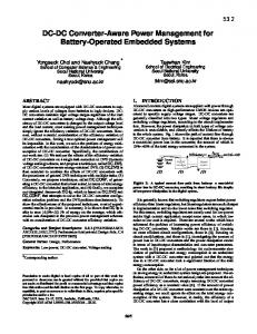
The conversion efficiencies of the prototype measured at the nominal input of 48 V dc are 93.12%, 93.056% and 90.33% at output current of 5, 10, and 20 A, respectively. The output ripple waveform (with noise) is shown in Fig. 8. With a small filter, the measured peak-to-peak output voltage ripple is 6.6 mV. Taking into account the high frequency voltage spike, the measured peak-to-peak ripple is 28.4 mV. Finally, Fig. 9 shows the zerovoltage turnon waveform of with the drain voltage fallen to zero before the gate drive signal takes on. VI. CONCLUSION A new dc–dc converter using a dual asymmetric half-bridge topology has been proposed for achieving very low output ripple
1962
IEEE TRANSACTIONS ON POWER ELECTRONICS, VOL. 22, NO. 5, SEPTEMBER 2007
Fig. 8. Measured output ripple voltage for V scale: 20 mV/div.
= 48 V and I = 20 A. Vertical
[3] P. L. Wong, P. Xu, P. Yang, and F. C. Lee, “Performance improvements of interleaving VRMs with coupling inductors,” IEEE Trans. Power Electron., vol. 16, no. 4, pp. 499–507, Jul. 2000. [4] P. Xu, Y. C. Ren, M. Ye, and F. C. Lee, “A family of novel interleaved dc–dc converters for low-voltage high-current voltage regulator module applications,” in Proc. IEEE Power Electron. Spec. Conf., 2001, pp. 1507–1511. [5] M. Takagi, K. Shimizu, and T. Zaitsu, “Ultra HIGH efficiency of 95% for dc–dc converter—Considering theoretical limitation of efficiency,” in Proc. IEEE Appl. Power Electron. Conf. Expo, 2002, pp. 735–741. [6] P. Imbertson and N. Mohan, “New PWM converter circuits combining zero switching loss with low conduction loss,” in Proc. Int. Telecommun. Energy Conf., 1990, pp. 179–185. [7] N. K. Poon and M. H. Pong, “A novel ZVS direct coupling converter (DCC),” in Proc. IEEE Power Electron. Spec. Conf., 1996, pp. 94–99. [8] M. L. Heldwein, A. Ferrari de Souza, and I. Barbi, “A primary side clamping circuit applied to the ZVS-PWM asymmetrical half-bridge converter,” in Proc. IEEE Power Electron. Spec. Conf., 2000, pp. 199–204. [9] R. Miftakhutdinov, A. Nemchinov, V. Meleshin, and S. Fraidlin, “Modified asymmetrical ZVS half-bridge dc–dc converter,” in Proc. IEEE Appl. Power Electron. Conf. Expo, 1999, pp. 567–574. [10] K. Rustom, W. Wu, W. Qiu, and I. Batarseh, “Asymmetric half bridge soft-switching PFC converter with direct energy transfer,” in Proc. IEEE Power Electron. Spec. Conf., 2002, pp. 676–681. [11] T. M. Chen and C. L. Chen, “Characterization of asymmetrical half bridge flyback converter,” in Proc. IEEE Power Electron. Spec. Conf., 2002, pp. 921–926. [12] N. K. Poon, C. P. Liu, M. H. Pong, and X. Xie, “Current Driven Synchronous Rectifier With Energy Recovery,” U.S. 6 134 131, 2000. [13] J. C. P. Liu, X. Xie, N. K. Poon, and B. M. H. Pong, “Practical solutions to the design of current-driven synchronous rectifier with energy recovery from current sensing,” in Proc. IEEE Appl. Power Electron. Conf. Expo, 2002, pp. 878–884. [14] F. N. K. Poon, C. P. Liu, and M. H. Pong, “Method and System for Providing a dc Voltage With Low Ripple by Overlaying Plurality of Ac Signals,” U.S. patent 6 697 266, 2002.
Fig. 9. Verification of zero-voltage switching of S .
voltage. The proposed converter requires a very small output filter that improves the conversion efficiency. High efficiency is maintained as a result of zero-current turnoff of the output rectifiers especially when synchronous rectifiers are used. The symmetric structure of the proposed converter also guarantees equal current sharing of the two rectifiers, thereby maximizing their utilization. Experimental results show that the output ripple current is reduced 9 times in the worst case when compared with a two-phase isolated interleaved converter, and about 13.12 times when compared with a single-ended forward converter operating with the same output filter and at the same switching frequency. The measured results are consistent with the analytical equations. The low output-ripple converter topology described in this paper has been granted a U.S. patent [14]. ACKNOWLEDGMENT The authors wish to thank the reviewer for prompting them to compare the proposed topology with conventional topologies, which has led to the inclusion of Section IV in this paper. REFERENCES [1] C. Chang, “Current ripple bounds in interleaved dc–dc power converters,” in Proc. Int. Conf. Power Electron. Drives, 1995, pp. 738–743. [2] F. V. P. Robinson, “The interleaved operation of power amplifiers,” in Proc. Int. Conf. Power Electron. Var. Speed Drives, 1998, pp. 606–611.
Joe C. P. Liu (M’99) was born in Hong Kong in 1970. He received the B.Sc. degree in electrical and electronic engineering from the University of Hong Kong, Hong Kong, in 1993 and is currently pursuing the Ph.D. degree at the Hong Kong Polytechnic University, Hong Kong. From 1993 to 1999, he held several industrial positions in switching power supply design. In 1999, he joined the Power Electronics Laboratory of the University of Hong Kong, Hong Kong, as a Principal Research Engineer. Presently he is a Principal Research Engineer with Powerelab Limited, Hong Kong. His research interest includes switching converter topologies, synchronous rectifiers, soft switching, and EMI modeling.
N. K. Poon (M’95) received the B.Eng. (with honors) degree in electronic engineering from the City University of Hong Kong, Kong Kong, in 1995, and the Ph.D. degree from the Hong Kong Polytechnic University, Hong Kong, in 2003. After graduation he has worked with Artesyn Technologies (Asia Pacific) Limited and the Power Electronics Laboratory of the University of Hong Kong, Hong Kong. He is presently with Powerelab Limited in Hong Kong, where he leads a research team working in computer-aided design, soft switching techniques, EMI modeling, PFC topologies, synchronous rectification, converter modeling, PWM inverters and fast transient regulators.
LIU et al.: LOW OUTPUT RIPPLE DC–DC CONVERTER
Bryan M. H. Pong (M’84–SM’96) was born in Hong Kong. He received the B.Sc. degree in electronic and electrical engineering from the University of Birmingham, U.K., in 1983 and the Ph.D. degree in power electronics from Cambridge University, Cambridge, U.K., in 1987. After graduation he became a Senior Design Engineer and then a Chief Design Engineer at National Semiconductor Hong Kong, where he was involved in electronic product design. Afterwards, he joined ASTEC International, Hong Kong, first as a Principal Engineer and then a Division Engineering Manager. He is now an Associate Professor with the University of Hong Kong, Hong Kong, where he is in charge of the Power Electronics Laboratory and leads a team to carry out research in switching power supplies. He co-holds a number of U.S. patents. His research interests include synchronous rectification, EMI issues, power factor correction, magnetic component design, soft switching and digital control.
1963
Chi K. Tse (M’90–SM’97–F’06) received the B.Eng. degree (with first class honors) in electrical engineering and the Ph.D. degree from the University of Melbourne, Australia, in 1987 and 1991, respectively. He is presently Chair Professor and Head of the Department of Electronic and Information Engineering, Hong Kong Polytechnic University, Hong Kong, and his research interests include power electronics and nonlinear systems. He is a Honorary Professor of Wuhan University, China, and Guest Professor of Southwest China Normal University, China. He is the author of Linear Circuit Analysis (London, U.K.: Addison-Wesley 1998) and Complex Behavior of Switching Power Converters (Boca Raton, FL: CRC Press, 2003), co-author of Chaos-Based Digital Communication Systems (Heidelberg, Germany: Springer-Verlag, 2003) and Chaotic Signal Reconstruction with Applications to Chaos-Based Communications (Beijing, China: TUP, 2005), and co-holder of a U.S. patent and two pending patents. He serves as an Associate Editor for the International Journal of Systems Science and as Guest Editor of a few other journals. Dr. Tse received the L.R. East Prize by the Institution of Engineers, Australia in 1987, the IEEE TRANSACTIONS ON POWER ELECTRONICS Prize Paper Award in 2001, the International Journal of Circuit Theory and Applications Best Paper Award in 2003, the the President’s Award (twice) for Achievement in Research, the Faculty’s Best Researcher Award, the Research Grant Achievement Award, and a few other teaching awards while with the Hong Kong Polytechnic University. From 1999 to 2001, he served as an Associate Editor for the IEEE TRANSACTIONS ON CIRCUITS AND SYSTEMS PART I—FUNDAMENTAL THEORY AND APPLICATIONS, and since 1999 he has been an Associate Editor for the IEEE TRANSACTIONS ON POWER ELECTRONICS. In 2005, he served as an IEEE Distinguished Lecturer.