By introducing backlash nonlinearities into the joints, we can simulate different degraded states and failure conditions. The backlashes may be due to loose ...
Machine Performance Degradation Monitoring Using Fuzzy CMAC H. Xu *, C. M. Kwan *, L. Haynes *, and J. D. Pryor ** * Intelligent Automation Inc., 2 Research Place, Suite 202, Rockville, MD 20850. ** United States Army, Space & Strategic Defense Command, P.O. Box 1500, Huntsville, AL 35807-3801.
Abstract Conventional approaches to failure detection use NN, Fuzzy or expert systems to detect failures (the machine is already down). We believe that if we can detect the machine performance degradation (early signs of failures), then we can prevent the occurrence of failures. Our idea is use a new type of NN, called Fuzzy CMAC. We put a smooth hyperbolic tangent (tanh) function at the output of the Fuzzy CMAC network with 1 denoting normal and -1 denoting the failure. The training of the network is performed by feeding known patterns of normal and failure conditions to it. When the network is applied to detect faults, if the output lies anywhere in between -1 and 1, it means the machine is in degraded state. If the output is close to 1, it means the system is close to normal but it is also on the verge of degrading. One major advantage of this method is its simplicity in implementation. A simple robot trajectory tracking example will be given to illustrate the idea.
Conventional structure to fault monitoring, detection, and diagnostics is shown in Fig. 1. It can be seen that only fault detection and diagnostics procedures are present but clearly there is no mechanism in the process to monitor the machine degradation. Also note that the whole approach is an after-the-fact method, i.e. fault already occurred. To prevent machine breakdown through proactive maintenance will not only reduce cost related to machined products but also minimizes cost related to damaged parts of machines. Observed symptoms (off-line)
Process
Sensing
Fault Diagnostics
Fire Strength A1
Fuzzy Rasoning Rules
S ai
u1
Associated Memory Cell Vector y
T-Norm
T-Norm
Weighted Sum T-Norm
An
u
z +
Input Space
B
1
Weight Adjustment
u2
S bi
B
n
e
T-Norm
Learning Rule W
i+1
= W i+
+
zd
β ( zd - z ) S / Σ S k
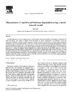
Fig. 2 Architecture of Fuzzy CMAC neural network. Our new approach is shown in Fig. 3
1. Introduction
Monnitoring on-line Fault Detection
Fuzzy Encodeing
Stop operation and repair
Fig. 1 Conventional structure of diagnostics. 2. Machine Degradation Monitoring Using Fuzzy CMAC Fuzzy CMAC (Cerebellar Model Arithmetic Computer) was developed by Intelligent Automation Incorporated (IAI) [1]. It synergistically combines the advantages of fuzzy logic and CMAC neural network and eliminates the some of the disadvantages of the two. IAI has successfully applied this network to active vibration control, finger print analysis, and chaotic time-series prediction. Fig. 2 illustrates the architecture of the Fuzzy CMAC. The Fuzzy CMAC inherits the preferred features of arbitrary function approximation, learning, and parallel processing from the original CMAC neural network [2], and the capability of acquiring and incorporating human knowledge into a system and the capability of processing information based on fuzzy inference rules from fuzzy logic. The combination of CMAC and fuzzy logic yields an advanced intelligent system architecture.
Off-line update of Fuzzy CMAC
1 Process
Sensing
Fuzzy CMAC for on-line machine degration monitoring, fault detection, and diagnostics
normal
degraded states Activate routine maintenance
degraded state failure
Stop operation and repair
-1 faults
Fig. 3 Fuzzy CMAC for machine diagnostics. One major difference between the Fuzzy CMAC approach and other approaches is that the Fuzzy CMAC performs machine degradation, fault detection and diagnostics at the same time. The reason that we can do this is by including a hyperbolic tangent function tanh at the end of each Fuzzy CMAC outputs. Since the tanh function takes values between -1 and 1, we can train the Fuzzy CMAC according to the following rules: an output of 1 implies normal operation, an output of -1 implies fault, and values between 1 and 1 implies the machine is in degraded states. We can arrange the outputs of the Fuzzy CMAC in such a way that each type of fault corresponds to one particular output of the Fuzzy CMAC. Hence if the output 1 of the Fuzzy CMAC is observed to have a value between -1 and 1, then we say fault number 1 is likely to occur soon since it is in the degraded state of fault number 1. Certain maintenance action should be taken to repair the causes of fault number 1. We can also perform off-line training of the Fuzzy CMAC on a regular basis. This may be necessary if the machine is sensitive to environmental conditions such as temperature, humidity, etc. These conditions may vary quite drastically in different seasons. Hence a periodic update of the Fuzzy CMAC will improve the performance of monitoring. 3. Simulation Study
Consider a two-link robot following a planar circular path. The robot equation is given by D(q )q�� + C (q , q� )q� = τ where ( m + m2 ) a12 + m2 a2 2 + 2m2 a1a 2 cos q2 D(q ) = 1 m2 a22 + m2 a1a2 cos q 2
m2 a22 + m2 a1a2 cos q2 , m2 a22
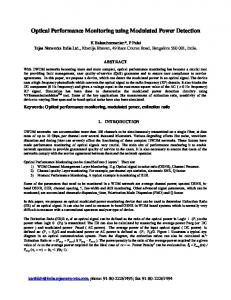
− m a a (2q� q� + q� 22 ) sin q� 2 C (q , q� ) = 2 1 2 1 22 , m2 a1a2 q�1 sin q2 m1 , m2 are masses of the links, a1 , a 2 are the link lengths, τ is the torque driving the robot. In the simulations, the following parameters are used: m1 = 8 , m2 = 5 , a1 = 0.8 , a 2 = 0.3 . By introducing backlash nonlinearities into the joints, we can simulate different degraded states and failure conditions. The backlashes may be due to loose screws in the joints. The faults are reflected in the form of tracking errors. The simulation data is generated by using the following SIMULINK model as shown in Fig. 4. The desired joint angles are generated from “Input 1” and “Input 2”. The robot trajectory is maintained on the circular path by using closed-loop feedback control. Although many complicated robust controllers could be used to control the robot, here we only use simple decoupled PID controllers because of its simplicity. The blocks “NL1” and “NL2” are saturation nonlinearities which simulate the torque limits of the two controllers. The joint angles are distorted by the backlash nonlinearities at the joints. We introduced four cases of backlash into the simulation; only one of the cases is the normal situation.
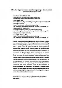
which can be considered as a pattern. For each case, we ran 200 different simulation runs by introducing random numbers into the backlash nonlinearities. A total of 800 patterns along the circular path in the clockwise direction, 200 for each case. We also generated 800 patterns in the counter clockwise direction. Half of these patterns were used to train the neural network. Another half were used for testing. We assigned one output to the network. In the monitoring process, we need to collect a lot of data points (70 elements in one pattern). Since the number of elements in one pattern vector (70) is beyond the capability of Fuzzy CMAC, we used a technique to extract the significant features from the input data vector. The technique is known as Principal Component Analysis (PCA) [3]. A brief review of the method is given in the Appendix. The inputs to the PCA are the pattern vectors (70 elements). The outputs of the PCA contains two significant components which are then fed into the Fuzzy CMAC for training. The feature space is shown in Fig. 5. There is only one output in the Fuzzy CMAC which indicates whether the robot tracking is normal (output = 1), degraded states (1 < output < 1) or abnormal (output = -1). Under normal operating conditions (small backlash), the output of the Fuzzy CMAC is 1. Cases 2, 3, and 4 correspond to failure conditions. If the backlash falls in the region between case 1 and cases 2, 3, and 4, then the output is between -1 and 1, indicating degraded states. Extensive tests showed the proposed methodology works extremely well.
Acknowledgment This research was supported by US Army Space & Strategic Defense Command under contract DASG60-95-C-0084
backlash at joint 1
BL1 [t,q1] desired angles [t,q2] Input2
Input1
+ Sum1 + Sum2
q1
PID NL1
PID 1
q2
PID NL2
PID 2
robot
References [1] Intelligent Automation Inc., “Fuzzy CMAC Neural Networks and Application to Flight Vehicle Control,” Phase I Technical Report to Ballistic Missile Defense Organization, Sept., 1994. [2] J.S. Albus, “A New Approach to Manipulator Control: The Cerebellar Model Articulation Controller (CMAC),” Journal of Dynamic System, Measurement, and Control, pp. 220-233, 1975. [3] S. Haykin, Neural Networks: A Comprehensive Foundation, Macmillan College Publishing Company, 1994.
BL2 backlash at joint 2
Fig. 4 Overall simulation scheme. There are four cases of backlash: Case 1: Normal behavior (minor nonlinearity) Both joints are introduced with a backlash between 0 to 6 degrees, i.e. random numbers are put into the backlash nonlinearities. Case 2: Significant backlash nonlinearity in joint 2 Joint 2 has a range of backlash between 0 to 6 degrees. Joint 1 has a range of backlash between 12 to 24 degrees. Case 3: Significant backlash nonlinearity in joint 1 Joint 1 has a range of backlash between 0 to 6 degrees. Joint 2 has a range of backlash between 12 to 24 degrees. Case 4: Significant nonlinearities in both joints Joints 1 and 2 both have a range of back lash between 12 to 24 degrees. We collected 35 measurements along the circular path to collect the deviations in x and y from the desired path. Therefore, there were 70 numbers (35 errors in x and 35 errors in y) in one simulation run. We put these 70 numbers into one single vector
2 1.5 1
Case 2 Normal, Case 1
0.5 Feature 2 0
Degraded states
-0.5 -1
Case 3
Case 4
-1.5 -2 -0.5
0
Feature 1
Fig. 5 Feature space of the patterns (outputs of PCA).
0.5