tor of our society: academic institutions, government agencies and a myriad of business enterprises. Commercial companies such as Google, Amazon, Akamai, ...
MDCSim: A Multi-tier Data Center Simulation Platform Seung-Hwan Lim, Bikash Sharma, Gunwoo Nam, Eun Kyoung Kim, and Chita R. Das Department of Computer Science and Engineering, The Pennsylvania State University University Park, PA 16802, USA Technical Report CSE 09-007 {seulim, bus145, gnam, ekkim, das}@cse.psu.edu
Abstract—Performance and power issues are becoming increasingly important in the design of large cluster based multitier data centers for supporting a multitude of services. Design and analysis of such large/complex distributed system often suffers from the lack of availability of an adequate physical infrastructure and the cost constraints especially in the academic community. With this motivation, this paper presents a comprehensive, flexible and scalable simulation platform for in-depth analysis of multi-tier data centers. Designed as a pluggable threelevel architecture, our simulator captures all the important design specifics of the underlying communication paradigm, kernel level scheduling artifacts, and the application level interactions among the tiers of a three-tier data center. The flexibility of the simulator is attributed to its ability in experimenting with different design alternatives in the three layers, and in analyzing both the performance and power consumption with realistic workloads. The scalability of the simulator is demonstrated with analyses of different data center configurations. In addition, we have designed a prototype three-tier data center on an IBA connected Linux cluster to validate the simulator. Using RUBiS benchmark workload, it is shown that the simulator is quite accurate in estimating the throughput, response time, and power consumption parameters. We then demonstrate the applicability of the simulator in conducting three different types of studies. First, we conduct a comparative analysis of the Infiniband Architecture (IBA) and 10 Gigabit Ethernet (10GigE) under different traffic conditions and with varying size clusters for understanding their relative merits in designing cluster-based servers. Second, measurement and characterization of power consumption across the servers of a three-tier data center is done. Third, we perform a configuration analysis of the Web server (WS), Application Server (AS), and Database Server (DB) for performance optimization. We believe that such a comprehensive simulation infrastructure is critical for providing guidelines in designing efficient and cost-effective multi-tier data centers.
I. I NTRODUCTION Design of high performance, power-efficient and dependable cluster based data centers has become an important issue, more so with the increasing use of data centers in almost every sector of our society: academic institutions, government agencies and a myriad of business enterprises. Commercial companies such as Google, Amazon, Akamai, AOL and Microsoft use thousands to millions of servers in a data center environment to handle high volume of traffic for providing customized (24x7) service. A recent report shows that financial firms spend around 1.8 billion dollars annually on data centers for their businesses [1]. However, it has been observed that data centers
contribute to a considerable portion of the overall delay for web-based services and this delay is likely to increase with more dynamic web contents. Poor response time has significant financial implications for many commercial applications. User dissatisfaction due to longer response times is a major concern as reported by a survey on the problems with WWW [2]. Further, the power consumption of data centers is also drawing much attention, leading to the concept of ”Green Data Centers”. As reported in [3], data centers in the U.S. consumed 61 billion kilowatt-hour of electricity in 2006 at the cost of $4.5 billion. This constitutes 1.5% of the total U.S. energy consumption for that year. It is estimated that data centers’ power consumption will increase by 4% to 8% annually and is expected to reach 100 billion kWh by 2011. Thus, future data center’s design must focus on three critical parameters: high performance, power/thermal-efficiency and reliability. In view of this, recent researches focus on the design of multi-tier cluster-based data centers, exploitation of high speed I/O interconnects and power management to meet the current demands of fast growing large data centers [4], [5], [6], [7]. Design of distributed web servers is primarily targeted at improving the throughput and reducing the response time [8], [9]. Also, with the increasing use of dynamic web contents, a multi-tier architecture provides a clean abstraction of different functionalities [10], [11]. Further, I/O interconnect technologies have a significant impact in supporting efficient inter/intra cluster communication in a multi-tier data center. In this context, researchers have attempted to examine the advantage of employing a user-level communication mechanism such as the InfiniBand Architecture (IBA) [12] in contrast to the traditional TCP/IP protocol in designing the underlying communication infrastructure to reduce the network overhead by minimizing the kernel involvement in message transfer [6]. Similarly, power management techniques and understanding power consumption in data centers have been attempted by a few researchers [7], [13]. There are three approaches for the analysis of a system, namely measurement, modeling and simulation. Measurement do provide an accurate methodology to analyze systems. However, many times, measuring large scale systems is not feasible, given the cost and time constraints. Modeling offers a simple representation of the construction and working of the
system of interest. However, the cost and overhead involved in the reconfiguration and experimenting with a model is substantially high [14]. Simulation fills in the above deficiencies by providing a flexible, operative working model of a system. A simulator can outline a more detail view of a system than modeling [14]. Simulation of a system is also an economically better option as compared to the real implementation of a system. Moreover, simulation saves the time spent on configuring test environments. Analysis of multi-tier data center has been done with respect to modeling and simulation in the past [6], [15]. However, the scope and scale of analysis is restricted to individual tier or with small size clusters. Further, in most of the studies on data centers, the size of system analyzed is limited because of practical difficulties encountered in testing large scale systems [16], [17]. Analysis done on small scale cannot always guarantee similar behavior or trend when the scalability is enhanced. Thus, there is a need to analyze system on a larger scale keeping in view the existing trend in data centers. Moreover, in spite of the growing popularity of multi-tier data centers, to the best of our knowledge, simulating a multi-tier data center including the functionalities of all the tiers together has not been attempted. Keeping in view the importance of growing data centers and the above limitations in the analysis of such concurrent and distributed systems, we propose a simulation platform for the design and analysis of large scale multi-tier data centers. Our simulation platform discussed above is comprehensive, flexible and scalable. The comprehensiveness comes from the fact that each salient feature of a multi-tier data center is implemented in detail and with much clarity. It is flexible as we can manipulate different features of the data center. For example, the number of tiers can be changed, the scheduling algorithms can be customized, the type of interconnection used can be altered and so also the communication mechanisms. Further, the layered architecture provides the ease in doing modification to any individual layer without affecting other layers. Simulation experiments are possible with large number of nodes across the cluster, making it scalable and apt to existing data centers’ trends. For the analysis of data center, we first designed and implemented a prototype three-tier data center on an IBA and 1GigE connected Linux cluster. The major components of this prototype included WS tier, AS tier and DB tier. The web traffic was generated by RUBiS [18] workload, which gets distributed using a simple round-robin web switch. Since the prototype was limited in terms of the number of cluster nodes, system configurations, and driving workloads, we designed the proposed simulation framework. The simulator was validated with RUBiS benchmark measurements on the above mentioned prototype data center. The average deviation of simulation results from real measurements was found to be around 10%. Using our simulator, we implemented three important applications. First, comparative analysis of IBA and 10GigE was performed under different cluster configurations and with vary-
ing load. Next, power measurement in multi-tier data center was done. Finally, a methodology for the determination of optimal cluster configurations in terms of performance (latency) through simulation experiments was discussed . Our experimental results for the comparative analysis between 10GigE and IBA show that 10GigE performs better than IBA under low traffic but as the number of clients increases, IBA outperforms 10GigE both with and without TCP Offload-Engine (TOE). From the power consumption comparison among IBA, 10GigE with/without TOE connected data centers with different cluster configurations and with increasing number of clients, it was observed that the power consumption increases with the increase in the traffic across the cluster. Also, the power usage was found to be varying for different cluster configurations even for the same total number of nodes. Further, simulations with different cluster configurations established the fact that increasing the number of nodes in a cluster does not always guarantee better performance. There are specific configurations (optimal distribution of nodes across each tier) that can achieve the desired level of performance. The rest of the paper is organized as follows. In Section II, we discuss the related works. The design of the simulation platform is described in Section III. Prototype design, system configuration and validation of simulator are discussed in Section IV. Our results and discussions are presented in Section V, followed by the concluding remarks and future directions in Section VI. II. R ELATED W ORK A few researchers have addressed the modeling of a multitier data center. Modeling or simulation of each individual tier separately in a multi-tier data center has been studied in [15], [19], [20], [21]. Modeling of a multi-tier data center has been done in few works [4], [5]. [4] models a multitier data center as a network of queues and Stewart et al. [5] models each service tier as a fine-grained component to capture practical implementations of each server. However, design of a simulation platform for the analysis of multi-tier data centers taking into account the effects of all tiers together has gone unaddressed in previous works. Balaji et al. [6] have shown the benefits of IBA in multitiered web services. However, the system analyzed in [6] is restricted in size and system capability in the sense that it does not include the Java 2 Enterprise Edition (J2EE) [22] based application servers, which have become the de facto standard for designing data centers. Our prototype data center includes J2EE specifications. Further, they conducted the comparison analysis with low traffic and small cluster sizes. In this paper, as part of an application of our simulator, we perform the evaluations and comparisons of IBA and 10GigE with/without TOE on a much larger scale and under high load conditions typical to the current data centers’ trends. Modeling of power consumption in computer systems has been done at various granularity levels, starting from large data center to individual components of a system either through real measurements, estimations from performance counters or 2
Front-end Tier/ Mid Tier/ Web Server Application Server
End Users (B2C)
Back-end Tier/ Database Server
DataGeneral
Web Server Application Server
Database Server Storage Server
Laptop
DataGeneral
Com mP rot
SD
BayN et wor ks
450- 12T S wich t
B aySt ac k
Uplikn Module
13
14
15 16 1
2
3
4
5
6
7
8
9
10
11
12
1
2 3
4
5 6
7 8
9 10 1112
100 10 FD x Acti yvit
Webswitch Computer
Partners (B2B) DataGeneral
Fig. 1.
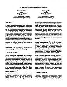
Functional Overview of the Simulation Platform
Fig. 2.
using a combination of both [23], [24]. Power management for communication protocols has been studied in previous researches [16], [25], [26]. [16] compared the power based benefits of using RDMA adapters, such as IBA and 10 GigE with TOE against TCP/IP Ethernet. However, they conducted their experiments by using only two servers and with just micro-benchmarks. Further, energy consumption in server farms using simulation is studied in [26]. However, the scale of simulation is restricted (results for only up to 32 nodes are shown). Our simulation results for power measurement across the servers of a data center span over much larger nodes cluster configuration. Besides, there have been significant researches on power management methodologies that focus only on individual tier such as web server tier without taking into consideration the effects of all the tiers of a multi-tier data center. For example, [13], [27] analyze only front end power and energy management techniques. [7] discusses local and cluster-wide power management techniques using just a web server simulator. Simulator proposed in this paper considers the effects of all tiers together and can accurately estimate power consumption across the servers of a multi-tier data center. To the best of our knowledge, no previous works have looked at multi-tier data center simulator, which can analyze a cluster based data center with detailed implementation of each individual tier. Also, power measurement in a large consolidated environment like a multi-tier data center has not been analyzed using a comprehensive multi-tier simulator in previous literatures. III. D ESIGN
OF
A Generic Three-Tier Data Center
abstraction provides the flexibility and scalability in analyzing various design details as described next. Intra-cluster communication is modeled at the communication layer. For intra-cluster communication, the simulator supports IBA and Ethernet over TCP/IP as the underlying interconnect technology. The IBA communication modules follow the semantics of the IBA specification [12] and support major functionalities of the IBA, including communication with Completion Queue (CQ) and Send/Receive Queues. Other communication paradigms/protocols can be incorporated into the communication layer by simply plugging in the appropriate timing parameters. At the kernel layer, we modeled the Linux scheduler 2.6.9, which maintains a run queue for each CPU in the system. Since we assumed all the CPUs in a node as one single resource, we have just one run queue for each server node. Each time the scheduler runs, it finds the highest priority task among communication and application processes in the simulator. If there are multiple tasks with the same priority, those tasks will be scheduled by the round-robin scheme. When calculating the time slice, the scheduler punishes CPU intensive tasks and rewards I/O intensive tasks as Linux 2.6.x. kernel does. The high level application/user layer captures the important characteristics of a three-tier architecture as shown in Figure 2. The user level layer consists of the following categories of processes - web server (WS), application server (AS), and database server (DB) processes; auxiliary processes like disk helper for supplementing server processes; communication processes such as Sender/Receiver processes. The front-end web server is the closest to the edge of a data center and is responsible for serving either static requests or forwarding dynamic requests to application server nodes. To serve static requests, it can be read from the memory or disks in a node. In our case, we use Apache [29] as the front end web server interface. The middle tier, the application server tier, is responsible for handling the dynamic web contents, and we use the publicly available JOnAS [30] for our research. On receiving the dynamic requests, the application server nodes
S IMULATION P LATFORM
In this section, we discuss the design and implementation issues of our simulation platform. The functional building blocks of our multi-tier data center simulator, written in CSIM [28], are shown in Figure 1. The simulation is configured into three layers (a communication layer, a kernel layer and a user-level layer) for modeling the entire stack starting from the communication protocols to the application specifics. Such a three layer 3
Requests from Web Switch
Web Server
Application Server NIC
Disk Helper
Sender Receiver
Apache Web Server
Database Server NIC
Disk Helper
Sender Receiver
Disk Helper
Disk
Scheduler Kernel Layer
Fig. 3.
User Layer
Disk
Scheduler
Sender Receiver
Kernel Layer
User Layer
Disk
Tomcat Web Container
mod_jk Apache Web Server
Apache Web Server
Scheduler Kernel Layer
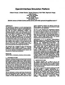
Architectural Details of the Three Layers of the Simulator
RMI
Database Server Tier
JOnAs EJB Container
MySQL
Application Server
Apache Web Server Clients
User Layer
Application Server Tier
Web Server Tier
Communication Layer
Fig. 4.
Tomcat Web Container
RMI
Application Server
Tomcat Web Container
JOnAs EJB Container
C-JDBC
MySQL
Application Server
RMI
JOnAs EJB Container
MySQL
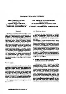
A Prototype Data Center
that of each node has been implemented in a lucid manner. For example, we implemented database synchronization and load distribution for web requests in the application layer. The task scheduler was deployed in the kernel layer and the communication primitives are captured in the low level communication layer.. Its flexibility comes from the fact that the simulator provides the ease to modify the behavior of any entity in a simulator without affecting other parts by simply plugging different parameters, policies, or even implementing different features. For instance, we need to only vary the latency timing parameters to analyze the behavior of both IBA and 10GigE network adapters without changing any other parts of the simulator. Also, we can analyze the behavior of several cluster configurations for optimizing various objective functions without having to rearrange or change our simulator. Moreover, although the current version of the simulator is currently used for performance and power analysis, it can be extended to study thermal behavior and reliability issues. The scalable aspect of the simulator enables it to simulate large data centers. There can be many possible applications of the simulator such as comparative performance analysis of high speed interconnects, power and thermal analysis, determination of optimal cluster configuration to meet a target performance level, fault tolerance and reliability of data centers.
process the business logic. Being in middle between the frontend and back-end in a data center, application servers include interfaces to both tiers: translating clients’ messages in HTML to SQL and vice versa. The AS nodes’ functionalities are based on J2EE specifications. To model EJB session beans [20] in our simulator, we implemented three main components - web container which takes care of the presentation logic, EJB container that handles business logic and controls interaction with the database. Finally, the database server, based on the SQL semantics [31], is dedicated for complex database transactions. It either primarily accesses the cached data in the database or sends a request to disks. From measurements on our prototype data center (discussed later) with the RUBiS workloads, we observe that 97% of the database requests are satisfied from the cache, thus, only 3% of the requests are directed to the disks. We use these cache and disk access rates in simulating the database tier. Since we assumed mirroring as data sharing method among the database servers, we modeled locking operation to ensure data coherence. We also assumed that there is one server process per node to simplify the implementation of each tier of our three-tier data center simulator. The architecture of our simulator is shown in Figure 3. Here, Network Interface Card (NIC) and Disk are devices and others are processes that reside inside the CPU in a server node. We assumed that CPU, Disk and NIC are basic computing resources in a node responsible to process requests. Each resource is modeled as an M/M/1 queue in the simulator. In the simulator, nodes separately process the requests which they receive through the communication layer. After processing the requests, they send the responses back through the communication layer and this procedure follows for each node in the cluster. Since we simulate each node independently, we can change the configuration of each tier easily, such as varying the total number of nodes in the entire cluster and the number of nodes for each tier. The main advantages of our simulation platform is that it is comprehensive, flexible and scalable. It is comprehensive as the critical behavior of an entire data center as well
IV. P ROTOTYPE C ONFIGURATION
AND
VALIDATION
In this section, we present the design and implementation of a prototype data center, the system configuration, and the simulator validation. As stated in the introduction, we have designed a prototype three-tier data centers to validate our simulator. A. A Prototype Design A three-tier data center prototype was designed and implemented as shown in Figure 4 for conducting actual measurements. The major components of this prototype include clients, WS tier, AS tier and DB tier. A simple round-robin web switch emulation was implemented to distribute client requests to the web server tier nodes. The web server nodes, in 4
which Apache 2.0.54 [29] is installed, communicate with the application server nodes through the mod jk connector module v.1.2.5. The maximum number of Apache processes was set to 512 to maximize the performance of WS tier. There are many application servers based on J2EE specifications which define the architecture and interfaces for developing Internet server applications for a multi-tier data center. Among them, JOnAS 4.6.6 [30], an open source application server, is installed on our prototype data center. TomcatWeb container 5.0.30 is integrated with JOnAS as the web container. Remote Method Invocations (RMI) provide intra-cluster communication among the AS tier servers. Sun’s JVM from JDK 1.5.0 04 for Linux was used to run JOnAS. EJB session beans version were employed to achieve the best performance as reported in [20]. Communication between AS-tier and DB tier was achieved through C-JDBC v.2.0.1 [32], which allows EJB container to access a cluster of databases. For the back-end tier, we used multiple machines running MySQL 5.0.15-0 Max [31]. Our prototype is implemented on varying number of dedicated nodes of a 96-node Linux kernel 2.6.9 cluster. Each of the these nodes has dual 64-bit AMD Opteron processors, 4 GBytes of system memory, Ultra320 SCSI disk drives and a Topspin host adapter which is InfiniBand v.1.1 compatible. The adapters are plugged into PCI-X 133Mhz slots. Each node has 1Gig-Ethernet adapter of Tigon 3 connected to 64 bit, PCIX 66Mhz slots. The default communication between all the server nodes is through 1GigE connection. In order to make IBA as our connection backbone instead of Ethernet, we ran all of the server applications with the SDP library (provided by Topspin) in our experiment. We used RUBiS [18] benchmark workload to collect actual measurement data for conducting our experiments since it was difficult to get real workloads because of the proprietary nature of Internet applications.
Fig. 5.
Estimated Latencies of various 10GigE adapters
quests according to the RUBiS benchmark, which follows the TPC-W compatible specification [33]. For generating traffic among different tiers (intra-cluster traffic), we used log-normal distribution as reported in [11] along with the parameters and think time interval of clients shown in Table II. In order to correctly simulate the characteristics of the AS and DB tier with dynamic requests, estimating CPU service times for AS and DB servers is essential. We estimate the CPU service time of each tier node. From measurements on the prototype, CPU utilization and throughput of each node is obtained. We then use the Utilization Law [4] to obtain the service time as shown in equation (1). ρ (1) T = τ where, T is the service time, ρ is the utilization of the busiest resource (CPU) and τ is the throughput of each node. Next for simulating 10GigE network adapter, we need the latency timing equation. Through linear regression analysis (Figure 5), we estimated the latency equations for two kinds of 10GigE implementations (with/without TOE) in terms of message size by obtaining latency from throughput [17] as per the following equation:
B. System Configuration and Workload Table I summarizes the system and network parameter values used in our experiments. These values were obtained from measurements on our prototype data center using micro benchmarks and hardware specifications. Clients generate re-
Latency = TABLE I T IMING PARAMETERS
Parameter from Measurement Context switch Interrupt overhead TCP connection Process creation overhead Disk read time Network latency (IBA) Network latency (1GigE) Parameter from Estimation Network latency (TOE) Network latency (10GigE)
Data Size T hroughput
(2)
As reported in [34], the hardware characteristics of 10GigE is almost the same as 1GigE. Further, the network latency for
Value (ms) 0.050 0.01 0.0815 0.352 7.89×2+(0.0168 × Size)+ (Size/368 − 1) × 7.89 0.003 + 0.000027 ×Size 0.027036 + 0.012 ×Size Value (ms, KB) 0.0005409 + 0.0010891 ×Size 0.0009898 + 0.0017586 ×Size
TABLE II T RAFFIC C HARACTERISTICS
Parameter WS → AS File Size AS → DB DB → AS AS → WS WS → client Dynamic Req/Total Req Avg. DB Req per Dynamic Req Think time interval
5
Value α = 0.1602, µ = 5.5974 α = 0.4034, µ = 4.7053 α = 0.5126, µ = 22.134 α = 0.5436, µ = 56.438 α = 0.5458, µ = 50.6502 0.672 2.36 Exponential with a mean of 7s
450
60 40 20 0
450
WS REAL 400 AS REAL DB REAL 350 WS SIM AS SIM 300 DB SIM
Latency(ms)
WS AS DB 100 WS sim AS sim 80 DB sim
Latency(ms)
Latency(ms)
120
250 200 150
1600 2400 number of clients
(a) 800 Clients
50 0 4800 5600 number of clients
6400
(b) IBA, 4WSs, 16ASs, 6DBs
4000
4800 5600 number of clients
6400
(c) 1G, 4WSs, 16ASs, 6DBs
Latency comparison between measurement and simulation
(b) 1600 Clients
Fig. 7.
150
50 4000
Fig. 6.
200
100
3200
(a) IBA, 2WSs, 6ASs, 3DBs
250
100
0 800
WS REAL 400 AS REAL DB REAL 350 WS SIM AS SIM 300 DB SIM
(c) 2400 Clients
(d) 3200 Clients
Service time CDFs from Measurement and Simulation
both 1GigE and 10GigE includes similar hardware overheads caused by switches and network interface card. Thus, we can safely assume that our simulator can be extended to capture the behavior of 10GigE.
power consumption. According to their power model, for a fixed operating frequency, both the power consumption of the server and the application throughput are approximately linear functions of the server utilization. The peak power consumption of the data center was obtained by simple linear regression between power and server utilization.
Our simulator is capable of measuring power consumption across the servers of a multi-tier data center. To incorporate power measurements in our simulator, we measured the server utilization using some modifications to the heuristics given in [13]. The server utilization was measured as
C. Simulator Validation We validated our simulator with 1GigE and IBA based prototype data centers with different number of nodes for each tier. The average latencies of each requests from simulation results were compared with those from real measurements as shown in Figure 6. Here, we selected the number of nodes for each tier in the prototype data center when the latency of requests was minimized. In Figure 6(a) and 6(b), the underlying network architecture was IBA. Figure 6(c) shows the latencies over 1GigE from actual measurements and simulation. In the above results, the latency of each tier from simulation closely matched with the real measurements, which implies our simulator’s underlying architecture captures critical paths in each tier. The average latencies from the simulator match closely with the average deviation of 10%. It should be noted that the above deviation is independent of either the number of nodes or the number of clients used in
Nstatic Astatic + Ndynamic Adynamic , (3) Monitor Period × # WS nodes where Nstatic and Ndynamic are the number of static and dynamic requests respectively; Astatic and Adynamic are the average execution time of static and dynamic requests respectively; Monitor Period is the time interval over which we measure server utilization and power. We divided the numerator of the equation for server utilization from [13] by the total number of web server nodes in the cluster, since our simulator processes the client requests in parallel at the front end tier [35]. We then computed the server utilization using the above equation. Power consumption is expressed as percentage of the peak power across the data center. We used the power model of Wang et.al [36] to estimate Userver =
6
140
90
WS(IBA) WS(10G TOE) 120 WS(10G)
AS(IBA) 80 AS(10G TOE) AS(10G) 70 60
Latency(ms)
Latency(ms)
100 80 60
50 40 30
40
20 20
10
0
0 800
1600 2400 number of clients
3200
800
(a) Latency in WS tier
6500
DB(IBA) 50 DB(10G TOE) 45 DB(10G)
Power comparison between measurement and simulation
5500 Throughput(r/s)
Latency(ms)
IBA 10gTOE 10G
6000
40
our simulations. Figure 7 shows the CDF plots of service times of each tier for the simulation and real measurements. According to [11], service time of an actual machine for RUBiS workload follows the Pareto distribution. We notice that the service time of each tier from our simulator closely matched with the real measurements. It implies that the modeled behavior for each tier in the simulator is very close to that of actual servers. From both the latency and CDF comparison, we confirm that our simulator well captured the critical behaviors to process requests and showed similar traffic characteristics to real environments. We validated the estimated power consumption using our simulator with real power measurements. Figure 8 shows the variation of power consumption with the number of clients corresponding to real and estimated power measurements. We used a power measurement device WT210 [37] to measure power usage of nine (the power strip used could only accommodate nine connections at a time) randomly chosen nodes from our prototype data center. These nine nodes were configured as 2 web servers, 6 application servers and 1 database server. The power consumption from our simulator closely matched with that of real measurements with an average deviation of around 3%. This result indicates that our simulator is capable of accurately estimating power consumption across the servers of a multi-tier data center.
3200
(b) Latency in AS tier
55
Fig. 8.
1600 2400 number of clients
35 30 25 20 15
5000 4500 4000 3500 3000
10
2500
5
2000 1500
0 800
1600 2400 number of clients
(c) Latency in DB tier Fig. 9.
3200
800
1600 2400 number of clients
3200
(d) Throughput
Comparison between IBA and 10GigE
for three configurations (IBA, 10GigE with TOE and 10GigE without TOE). We used 2 WS nodes, 6 AS nodes, and 3DB nodes for this simulation. Notice that the latency of WS and AS includes the communication overhead between WS and AS and between AS and DB, respectively. We observe that 10GigE, regardless of TOE, has a better or very similar performance over IBA in latency measurement, provided the number of clients is under 3200. However, with the increase in traffic beyond 3200 clients, the latency of IBA comes out to be 14% smaller than 10GigE with TOE and 26.7% lesser than 10GigE without TOE. Under high traffic, the communication cost which is determined by the mean number of jobs in communication layer is a dominant factor of the response time. Based on the queuing theory, the mean number of jobs in a queue, J can be obtained by J = λ × T, (4)
V. P ERFORMANCE E VALUATION
where λ is the inter-arrival rate of requests and T is the mean service time of a single request. Accordingly, given the same inter-arrival rate of requests, the latency under high traffic is mainly affected by the mean service time of a single request, which is the average latency of a single file for the workload in our simulation. Even though the file sizes vary from 1.5KB to 16KB for the RUBiS workload, most of them are clustered around 2.5KB [11]. As shown in Figure 10, the latencies of 10GigE with TOE and without TOE are greater than that of IBA with 2.5KB file size. Hence, IBA has the smallest response time among all the three network interconnections with high communication workload. We observe that the latency for the DB tier in case of IBA is
In this section, we demonstrate three important applications using our simulation platform. First, comparison between two popular interconnection networks is done in Section V-A. Second, power estimation using simulator is elaborated in Section V-B. Finally, performance prediction according to various system configuration is described in Section V-C. A. Comparison between IBA and 10GigE We conducted comparative performance analysis of 10GigE and IBA for three-tier data centers in terms of latency and throughput. The graphs in Figure 9 depict the average latencies and throughput of requests in terms of the number of clients 7
0.01
are under utilized, and so do not exhibit large power usage. However, with the increase in the traffic, server utilization is enhanced to make the servers derive more power supply. As we observe, the power consumption varies with different cluster configurations even for the same total number of nodes. This implies the dependency of some specific tier in deciding the power dominance. These results provide one with the insight into determining the particular configuration, which has a comparatively less power consumption across the cluster (this can be especially important for the designer of a multi-tier data center, where he has to determine the distribution of the number of nodes across each tier based on power efficiency).
IBA 10G TOE 10G
0.009 0.008
Latency(ms)
0.007 0.006 0.005 0.004 0.003 0.002 0.001 0 0
1
2
3
4
5
Message Size(KB)
Fig. 10.
Latency vs message size for different network architectures
C. Server Configuration To demonstrate the scalability and flexibility of our simulator, we conducted performance analysis of three-tier data center with increased number of nodes and with different interconnection networks. Figure 12 shows the variation of latency with different number of clients for 32, 64, and 128 nodes respectively. The combination of the number of nodes in each tier was selected randomly. We observe that the performance of the data center in terms of latency improves (with the decrease in latency) with an increase in the total number of nodes in the system. This is due to the efficient distribution of system load across multiple nodes of the tiers. However, we observe that this trend is violated for the case with 128 nodes as shown in Figure 12(c). This is due to the large overhead caused by the DB tier locking operation, which causes the total response time to be dominated by the DB portion of latency. These results imply that the performance might not be enhanced in proportion to the number of total nodes. The underlying mechanisms in each server may cause unexpected results if the scalability increases. The above results demonstrate that even without real measurement, we can suggest, for given system characteristics, the right choice among possible combinations of server configuration by the simulation. Next we examine latency variations for a fixed number of total nodes in a data center for different cluster configurations. Figure 13 depicts the results. We observe that performance of a data center in terms of latency varies based on the different configuration of nodes selected for each tier and also with the type of interconnection used. Also, notice that a better configuration of the system for minimizing the response time can be achieved by selecting more number of AS nodes than WS and DB nodes. This is because AS nodes have CPU intensive jobs and interfaces with two other ends, thus increasing them efficiently distributes the load across the cluster. Thus, our simulator can be used to change various configurations to determine the desired distribution of nodes across the cluster for optimizing performance.
much higher than that of 10GigE with and without TOE under high traffic (3200 clients as shown in Figure 9(a), 9(b), and 9(c)). This can be explained due to the fact that the throughput of IBA in case of 3200 clients is higher than that of 10GigE , which increases the number of requests generated for the DB tier and thus degrades the response time of the DB tier. This is due to the fact that the blocking operation, which ensures consistency among databases, can cause system overheads in the database servers when the number of concurrent writing operation increases. Also, we notice that the WS part of bar graphs is negligible in some results. This is because the service time of WS which includes communication overheads between AS and WS is less than 10% of the overall latency in most experiments. B. Power Measurement As mentioned before, our simulator can estimate power consumption across the servers of a data center. The flexibility offered by our simulator allows one to measure the power consumption for any selected number of clients and with any chosen cluster configuration. From Figure 8, we notice that the power consumption across the cluster nodes increases with the increase in the traffic from 800 to 3200 clients for both the prototype data center as well as the simulation platform. Figure 11 shows the estimated power consumption using our simulator across 64 nodes clustered data center connected with IBA, 10GigE with TOE and 10GigE without TOE respectively. Here, S1, S2, and S3 represent three different cluster configurations with varying number of nodes in the WS tier, AS tier, and DB tier respectively for the same total number of nodes, 64 nodes. In S1, 8 web servers, 32 application servers, and 24 database servers were used. In S2, 8 web servers, 40 application servers, and 16 database servers were used. S3 consisted of 16 web servers, 32 application servers, and 16 database servers. We expressed power as percentage of peak power in Figure 11. As we observe from Figure 11, power consumed when the number of clients is less, comes out to be more or less same for different cluster configurations in all the three cases (IBA, 10GigE with TOE, 10GigE without TOE). This is because when the traffic is less, the servers
VI. C ONCLUSIONS In this paper, we first designed and implemented a prototype three-tier IBA and 1GigE connected data center. Since the prototype was limited in terms of the number of cluster nodes, 8
(a) IBA, 64 nodes
(b) 10G TOE, 64 nodes Fig. 11.
80 70
40
60 50 40
Estimated Power Consumption 1000
WS(IBA) WS(10gTOE) WS(10G) AS(IBA) AS(10gTOE) AS(10G) DB(IBA) DB(10gTOE) DB(10G)
WS(IBA) 900 WS(10gTOE) WS(10G) 800 AS(IBA) 700 AS(10gTOE) AS(10G) 600 DB(IBA) DB(10gTOE) 500 DB(10G) 400
Latency(ms)
90
WS(IBA) WS(10gTOE) 120 WS(10G) AS(IBA) 100 AS(10gTOE) AS(10G) 80 DB(IBA) DB(10gTOE) DB(10G) 60
Latency(ms)
Latency(ms)
140
(c) 10G, 64 nodes
30
300
20 20 0
100
0 4000 4800 number of clients
5600
3200
(a) 32nodes(4,20,8)
4000 4800 5600 number of clients
0
6400
3200
(b) 64nodes(8,40,16) Fig. 12.
Latency(ms)
30
WS(IBA) 140 WS(10gTOE) WS(10G) 120 AS(IBA) AS(10gTOE) 100 AS(10G) DB(IBA) DB(10gTOE) 80 DB(10G) 60
20
40
10
10
20
0 3200
4000 4800 number of clients
5600
(a) 64nodes(8,32,24)
0 3200
4000 4800 5600 number of clients
6400
(b) 64nodes(8,40,16) Fig. 13.
6400
160
WS(IBA) 80 WS(10gTOE) WS(10G) 70 AS(IBA) AS(10gTOE) 60 AS(10G) DB(IBA) 50 DB(10gTOE) 40 DB(10G)
20 0
5600
(c) 128nodes(16,80,32)
90
30
4800
Latency with varying number of nodes (WS, AS, DB)
100
WS(IBA) 90 WS(10gTOE) WS(10G) 80 AS(IBA) 70 AS(10gTOE) AS(10G) 60 DB(IBA) DB(10gTOE) 50 DB(10G) 40
4000
number of clients
Latency(ms)
3200
Latency(ms)
200
10
3200
4000 4800 number of clients
5600
(c) 64nodes(16,32,16)
Latency with varying number of nodes for each tier (WS, AS, DB)
first study detailed a comparative analysis of the performance of IBA and 10GigE under varying cluster sizes, network load and with different tier configurations. The results from this experiment indicated that 10GigE with TOE performs better than IBA under light traffic. However, as the load increases, IBA performs better than 10GigE both with and without TOE. Next, we introduced a methodology to perform power measurement in a multi-tier data center using our simulator.
system configurations, and driving workloads, we presented a comprehensive, flexible and scalable simulation platform for the performance and power analysis of multi-tier data centers. The simulator was validated with RUBiS benchmark measurements on the above mentioned prototype data center. Using three application studies, we demonstrated how designer of a multi-tier data center might use the proposed simulation framework to conduct performance and power analysis. The
9
Finally, using simulation platform, confguration analysis for performance optimization in terms of reduced network latency was demonstrated. As a part of our future work, we intend to test our simulation platform with diverse set of workloads besides RUBiS. Further, we plan to extend our simulation platform for conducting thermal analysis, reliability measurement and servers’ provisioning (i.e, determination of the optimal number of servers in each tier based on performance and power) in a multi-tier data center. Also, we are working towards making our simulator a publicly available tool for use in research community in near future.
[15] T. F. Abdelzaher, K. G. Shin, and N. Bhatti, “Performance guarantees for web server end-systems: A control-theoretical approach,” in IEEE Transactions on Parallel and Distributed Systems, vol. 13, no. 1, Jan 2002. [16] “Evaluating high performance communication: a power pespective,” in 23rd International Conference on Supercomputing, to be appeared, 2009. [17] W. B. Feng, C. P. Baron, L. Bhuyan, and D. Panda, “Performance characterization of a 10-Gigabit Ethernet TOE,” in High Performance Interconnects, 2005. Proceedings. 13th Symposium on, 2005, pp. 58 – 63. [18] C. Amza, E. Cecchet, A. Chanda, A. L. Cox, S. Elnikety, R. Gil, J. Marguerite, K. Rajamani, and W. Zwaenepoel, “bottleneck characterization of dynamic web site benchmakrs,” in Third IBM CAS Conference, 2002, 2002. [19] D. Villela, P. Pradhan, and D. Rubenstein, “Provisioning servers in the application tier for e-commerce systems,” ACM Trans. Interet Technol., vol. 7, no. 1, p. 7, 2007. [20] E. Cecchet, J. Marguerite, and W. Zwaenepoel, “Performance and scalability of EJB applications,” SIGPLAN Not., vol. 37, no. 11, pp. 246–261, 2002. [21] J. Chen, G. Soundararajan, and C.Amza, “Autonomic provisioning of backend databases in dynamic content web servers,” Autonomic Computing, 2006. ICAC ’06. IEEE International Conference on, pp. 231–242, June 2006. [22] Sun Microsystems, Inc., “J2EE: Java 2 Platform Enterprise Edition,” 2003, available from http://java.sun.com/j2ee/. [23] S. Gurumurthi, A. Sivasubramaniam, M. J. Irwin, N. Vijaykrishnan, M. Kandemir, T. Li, and L. K. John, “Using complete machine simulation for software power estimation: The softwatt approach,” in HPCA ’02: Proceedings of the 8th International Symposium on HighPerformance Computer Architecture. Washington, DC, USA: IEEE Computer Society, 2002, p. 141. [24] W. Wu, L. Jin, J. Yang, P. Liu, and S. X.-D. Tan, “Efficient power modeling and software thermal sensing for runtime temperature monitoring,” ACM Trans. Des. Autom. Electron. Syst., vol. 12, no. 3, pp. 1–29, 2007. [25] C.-H. Hsu and W.-C. Feng, “A power-aware run-time system for highperformance computing,” in SC ’05: Proceedings of the 2005 ACM/IEEE conference on Supercomputing. Washington, DC, USA: IEEE Computer Society, 2005, p. 1. [26] V. W. Freeh, F. Pan, N. Kappiah, D. K. Lowenthal, and R. Springer, “Exploring the energy-time tradeoff in mpi programs on a power-scalable cluster,” in IPDPS ’05: Proceedings of the 19th IEEE International Parallel and Distributed Processing Symposium (IPDPS’05) - Papers. Washington, DC, USA: IEEE Computer Society, 2005, p. 4.1. [27] M. Elnozahy, M. Kistler, and R. Rajamony, “Energy conservation policies for web servers,” in USITS’03: Proceedings of the 4th conference on USENIX Symposium on Internet Technologies and Systems. Berkeley, CA, USA: USENIX Association, 2003, pp. 8–8. [28] Mesquite Software, “CSIM,” http://www.mesquite.com. [29] The Apache Software Foundation, “The Apache HTTP Server Project,” 2003, http://httpd.apache.org. [30] ObjectWeb Consortuim, “JOnAS,” 2006, http://jonas.objectweb.org. [31] MySQL, “MySQL,” 2006, available from http://www.mysql.com. [32] ObjectWeb Consortuim, “C-JDBC,” 2006, http://c-jdbc.objectweb.org. [33] D. F. Garcia and J. Garcia, “Tpc-w e-commerce benchmark evaluation,” Computer, vol. 36, no. 2, pp. 42–48, 2003. [34] G. E. Alliance, http://www.10gea.org. [35] B. Urgaonkar, P. Shenoy, A. Chandra, and P. Goyal, “Dynamic provisioning of multi-tier internet applications,” in Autonomic Computing, 2005. ICAC 2005. Proceedings. Second International Conference on, 2005. [36] Z. Wang, C. McCarthy, X. Zhu, P. Ranganathan, and V. Talwar, “Feedback control algorithms for power management of servers,” in 3rd Workshop on Feedback Control Implementation and Design in Computing Systems and Networks (FeBID’08), Jun 2008. [37] Yokogawa Electric Corporation, “WT210 Digital Power Meter User’s Manual,” May 1998.
R EFERENCES [1] FinanceTech, “FinanceTechnology Network,” 2009, available from http://www.financetech.com. [2] Graphic, Visualization, & Usability Center, “GVU’s 10th WWW User Survey,” December 1998, available from http://www.gvu.gatech.edu/user_surveys/ survey199810/. [3] M. Marwah, R. Sharma, R. Shih, C. Patel, V. Bhatia, M. Mekanapurath, R. Velumani, and S. Velayudhan, “Data analysis, visualization and knowledge discovery in sustainable data centers,” in COMPUTE ’09: Proceedings of the 2nd Bangalore Annual Compute Conference on 2nd Bangalore Annual Compute Conference. New York, NY, USA: ACM, 2009, pp. 1–8. [4] B. Urgaonkar, G. Pacifici, P. Shenoy, M. Spreitzer, and A. Tantawi, “An analytical model for multi-tier internet services and its applications,” in SIGMETRICS ’05: Proceedings of the 2005 ACM SIGMETRICS international conference on Measurement and modeling of computer systems. New York, NY, USA: ACM Press, 2005, pp. 291–302. [5] C. Stewart and K. Shen, “performance modeling and system management for multi-component online service,” in NSDI ’05: 2nd Symposium on Networked Systems Design & Implementation, 2005. [6] P. Balaji, S. Narravula, K. Vaidyanathan, S. Krishnamoorthy, J. Wu, and D. K. Panda, “Sockets Direct Protocol over InfiniBand in clusters: is it beneficial?” in ISPASS ’04: Proceedings of the 2004 IEEE International Symposium on Performance Analysis of Systems and Software. Washington, DC, USA: IEEE Computer Society, 2004, pp. 28–35. [7] R. Bianchini and R. Rajamony, “Power and energy management for server systems,” Computer, vol. 37, no. 11, pp. 68–76, Nov. 2004. [8] M. Aron, D. Sanders, P. Druschel, and W. Zwaenepoel, “Scalable Content-aware Request Distribution in Cluster-based Network Servers,” in Proceedings of the USENIX 2000 Annual Technical Conference, June 2000, pp. 323–336. [9] V. S. Pai, M. Aron, G. Banga, M. Svendsen, P. Druschel, W. Zwaenepoel, and E. Nahum, “Locality-Aware Request Distribution in Cluster-Based Network Servers,” in Proceedings of the Eighth International Conference on Architectural Support for Programming Languages and Operating Systems, 1998, pp. 205–216. [10] W. Eckerson, “Three tier client/server architecture: Achieving scalability, performance, and efficiency in client server applications,” Open Information Systems, vol. 10, no. 1, January 1995. [11] D. Ersoz, M. S. Yousif, and C. R. Das, “Characterizing network traffic in a cluster-based, multi-tier data center,” in ICDCS ’07: Proceedings of the 27th International Conference on Distributed Computing Systems. Washington, DC, USA: IEEE Computer Society, 2007, p. 59. [12] InfiniBand Trade Association, “InfiniBand Architecture Specification, Volume 1 & 2, Release 1.2,” October 2004, http://www.infinibandta.org. [13] C. Rusu, A. Ferreira, C. Scordino, and A. Watson, “Energy-efficient real-time heterogeneous server clusters,” in RTAS ’06: Proceedings of the 12th IEEE Real-Time and Embedded Technology and Applications Symposium. Washington, DC, USA: IEEE Computer Society, 2006, pp. 418–428. [14] A. Maria, “Introduction to modeling and simulation,” in WSC ’97: Proceedings of the 29th conference on Winter simulation. Washington, DC, USA: IEEE Computer Society, 1997, pp. 7–13.
10