Available online at www.ijarmate.com
International Journal of Advanced Research in Management, Architecture, Technology and Engineering (IJARMATE) Vol. 2, Special Issue 2, March 2016.
MITIGATION OF VOLTAGE SAG USING DYNAMIC VOLTAGE RESTORER WITH SUPER CAPACITOR S.Balasubramani,1 S.Akshaya2, A.Karthick balaji3, S.Harirajan4, M.Ramesh Babu5 Assistant Professor, Electrical and Electronics Engineering, Jerusalem College of Engineering, Chennai, India1. UG Scholar, Electrical and Electronics Engineering, Jerusalem College of Engineering, Chennai, India2. UG Scholar, Electrical and Electronics Engineering, Jerusalem College of Engineering, Chennai, India3. UG Scholar, Electrical and Electronics Engineering, Jerusalem College of Engineering, Chennai, India4. Professor ,St.Joseph's College of Engineering Chennai, India5
[email protected],
[email protected],
[email protected],
[email protected],4
[email protected]
Abstract— The mitigation of voltage sag which caused in the power system by the system fault. It also affect the sensitive equipment present in the system. This will result in critical financial losses so the need for overcoming the loss dynamic voltage restorer (DVR) has been introduced. DVR has dynamic capabilities which is to compensate voltage sag and to restore its line voltage to the nominal value. Thus the super capacitor based DVR is using the proportional integral (PI) controller. This paper is proposed to maintain the power quality in the power system. Keywords— Voltage sag, Power quality, Dynamic voltage restorer, Voltage source converter.
I.
INTRODUCTION
Power quality is termed as any power problem manifested in voltage, current or frequency deviation that results in failure or mis-operation of customer equipment. Consumers are concerned with power quality because it has best economic utilities, customers and suppliers of load equipment. Power quality problems are because of increased use of sensitive equipment in the power system, industries and communication system. The disturbances of power quality are transients voltage sag, voltage swell, under voltage and over voltage. Due to lightning in the power distribution and transmission system voltage sag occurs. Sag depends on two factor voltage and duration of time. Super capacitor is used to store energy. It is connected across the capacitor and battery. When the super capacitor is compared with the normal capacitor it has more advantages as maintenance free and high reliability. The features of the super capacitor are short charge time, long service life, good temperature characteristics and green environment.. II.
DYNAMIC VOLTAGE RESTORER (DVR)
Dynamic voltage restorer is a series static compensator. DVR is used to inject voltage when the voltage sag occur in the power system during fault. DVR function is to inject a dynamically controlled voltage in series to the bus voltage by means of a boost transformer for voltage restoration and
regulation. DVR is also referred as series voltage booster (SVC).Both SVC and SSC device utilizes solid state or static of power electronics components. To restore the load voltage to the pre-sag condition DVR provides the controllable voltage to the source voltage to restore the load voltage. The template is used to format your paper and style the text. All margins, column widths, line spaces, and text fonts are prescribed; please do not alter them. You may note peculiarities. For example, the head margin in this template measures proportionately more than is customary. This measurement and others are deliberate, using specifications that anticipate your paper as one part of the entire proceedings, and not as an independent document. Please do not revise any of the current designations. III.
CONTROL TECHNIQUES OF DVR
A. Linear controllers The three main voltage controllers are open loop (feed forward), closed loop (feedback) and multi loop controller. Because of the simplicity and fastness the feed forward voltage controller is the primary side of the DVR. Here the supply voltage is continuously monitored and compared to the reference voltage. If it exceeds the certain tolerance, the DVR injects the required voltage. In the feedback voltage controller, the missing voltage is supplied by the DVR at supply bus in a feedback loop. This controller has the advantage of accurate response, but it is complex and time delayed. Multi loop controller has outer loop and inner loop. Outer loop is to control the DVR voltage and inner loop to control the load current. B. Non-linear controllers Since DVR is a non-linear system it is more suitable. Due to the presence of power of semiconductor switches in Inverter Bridge, the DVR is a non -linear system. The most non-linear controllers are artificial neural network (ANN), Fuzzy logic (FL) and Space vector pulse width modulation (SVPWM).
All Rights Reserved @ 2016 IJARMATE
425
Available online at www.ijarmate.com
International Journal of Advanced Research in Management, Architecture, Technology and Engineering (IJARMATE) Vol. 2, Special Issue 2, March 2016.
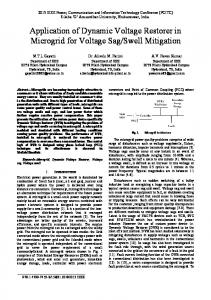
ANN control method has adaptive and self-organization capacity. When the mathematical formulation is not possible FL controllers are used. SVPWM control method is used to adopt a space vector of the inverter voltage to get better performance. C. PI controller The PI controller integrates the error between the feedback and reference current to generate a voltage variable value. PI controller has some advantages constant switching frequency, closed loop control, small current ripple and low acoustic noise. PI controller can be used in all types of feedback system. The oscillation and forced steady state error resulting in operation of on-off controller will be eliminated in PI controller. Since PI controller does not predict what will happen future it will not increase the speed of response. This problem can be solved by introducing derivative mode. Because the derivative mode The oscillation and forced steady state error resulting in operation of on-off controller will be eliminated in PI controller. Since PI controller does not predict what will happen future it will not increase the speed of response. This problem can be solved by introducing derivative mode. Because the derivative mode has the ability to predict what will happen with the error in future. PI controllers are very often used in industries. IV. SUPER CAPACITOR Super capacitor or ultra-capacitor can be defined as that no chemical reaction takes place when energy is stored or discharged and so ultra-capacitor can go through hundreds and thousands of charging cycles without any degradation. Ultra capacitor consists of a porous electrode, electrolyte and a current collector. There is a membrane which separates the positive and negative plate is called separator. When the voltage is applied to the positive plate, it attracts negative ions from electrolyte and when the voltage is applied to the negative plate, it attracts positive ions from electrolyte. Due to this, there will be a formation of layer of ions will occur on the both side of the plate. This formation is called as double layer formation. The distance between the plates is in the order of angstroms. The amount of energy stored in the ultra-capacitor is very large when compared to the standard capacitor because of the enormous surface area created by the porous carbon electrode.
a.
Disadvantages: 1. They have low energy density. 2. Individual cells show low voltage. 3. Not all the energy can be utilized during discharge.
b.
Applications: 1. Used in electronic applications, industrial lasers and medical equipment’s. 2. Used for load leveling the life of batteries. 3. Used in wireless communication system for uninterrupted service. V. SIMULATION
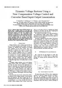
The model shown in Fig 2 is the Simulink Model of the system with DVR control using a Super Capacitor. The system is designed for a 415 Voltage and a minimum load. In the system, the source supplies the load at the end. The load when increased or on addition of an extra load to the system there occurs a voltage sag in the system. The addition load is added at the interval of 0.2 to 0.4 seconds. The voltage in the line is sensed and is given to a converter through a Super Capacitor. and it charges and discharges at a very rapid speed so that it behaves just like a battery and the only problem is the injection of distortion which can the seen in the output waveform. The Super Capacitor helps in maintaining reliability and quality of the power transferred. The output from the converter is fed as the DC input to the inverter from which the output is obtained as an AC voltage which is injected into the line for compensation. The DVR model is simulated by the following parameters shown in Table I. TABLE I.
SNO 1 2 3 4 5 6
DESIGN PARAMETERS
COMPONENT AC phase-to-phase voltage System frequency Source resistance Boost transformer Filter inductance Filter resistance-capacitance
RANGE 440 V 50 Hz 1Ω Ideal 8mH 10Ω,20µF
Fig. 1. Super Capacitor with plate seperator Fig. 2. Simulink Model of System with DVR using Super Capacitor
All Rights Reserved @ 2016 IJARMATE
426
Available online at www.ijarmate.com
International Journal of Advanced Research in Management, Architecture, Technology and Engineering (IJARMATE) Vol. 2, Special Issue 2, March 2016.
VI. RESULTS The waveforms that are obtained in the input or source side and the output or end user side of the system are shown below. Figure 3 shows the voltage waveform of the system when there is no sag with optimal loading, an additional load is added to the system so sag is created and is shown in Figure 5. During loading at extreme conditions the injected voltage and current by the converter for the voltage compensation during sag is also shown in the figure6.
Fig. 3. Input voltage waveform of the system
Fig. 4. Injected Voltage and current by the DVR
Fig. 5. Voltage Sag at the Source Side
VII. CONCLUSION The DVR system with Super capacitor is explained in this paper. The Super Capacitor increases the reliability of the system. The super capacitor is used in order to transfer the real power from the converter to the inverter dc link. The results shows that the sag due to the additional load in the system is compensated by the inverter system which obtains the reliable DC supply from the converter. The compensated waveform and the injected voltages are shown in the waveforms above. The MATLAB model of the system shows the working of the converter with a Super Capacitor. The voltage from the inverter is used for compensation of the line voltage. VII. REFERENCES [1] Bach Q. Khanh, J. Lian, B. Ramachandran, S. Srivastava, D. Cartes , “Mitigating Voltage Sags Due to DOL Starting of Three Phase Asynchronous Motors Using Dynamic Voltage Restorer (DVR)”, 2012 IEEE. [2] A. Khoshkbar Sadigh, Student Member, IEEE, and K. M. Smedley, Fellow, IEEE, “Review of Voltage Compensation Methods in Dynamic Voltage Restorer (DVR)”, 2012 IEEE. [3] Firouz Badrkhani Ajaei, Student Member, IEEE, Shahrokh Farhangi, and Reza Iravani, Fellow, IEEE, “Fault Current Interruption by The Dynamic Voltage Restorer”, IEEE transactions on Power Delivery, Vol. 28, No. 2, April 2013. [4] Parag Kanjiya, Bhim Singh, Ambrish Chandra, and Kamal Al-Haddad, Fellow, IEEE, ““SRF Theory Revisited” to Control Self-Supported Dynamic Voltage Restorer (DVR) for Unbalanced and Nonlinear Loads”, IEEE TRANSACTIONS ON INDUSTRY APPLICATIONS, VOL. 49, NO. 5, SEPTEMBER/OCTOBER 2013. [5] Yong Lu, Student Member, IEEE, Guochun Xiao, Member, IEEE, Bo Lei, Student Member, IEEE, Xuanlv Wu, Student Member, IEEE, and Sihan Zhu, “A Transformerless Active Voltage Quality Regulator With the Parasitic Boost Circuit”, IEEE TRANSACTIONS ON POWER ELECTRONICS, VOL. 29, NO. 4, APRIL 2014. [6] Ali Keyhani, Fellow, IEEE, and Abir Chatterjee, Student Member, IEEE, Automatic Generation Control Structure for Smart Power Grids, IEEE TRANSACTIONS ON SMART GRID, VOL. 3, NO. 3, SEPTEMBER 2012 [7] Abdul Mannan Rauf and Vinod Khadkikar, Member, IEEE, Integrated Photovoltaic and Dynamic Voltage Restorer System Configuration, IEEE TRANSACTIONS ON SUSTAINABLE ENERGY, 2015 [8] Younhyun Jung, Jinman Kim, IEEE, Member, Michael Fulham, and David Dagan Feng, IEEE, Fellow, Opacity-driven volume clipping for slice of interest (SOI) visualisation of multi-modality PET-CT volumes, IEEE 2015 [9] Yuan Liu, Student Member, Vijay Vittal, Fellow,Distribution Side Mitigation Strategy for Fault Induced Delayed Voltage Recovery, 2014 IEEE [10] Surendra Singh Chhajta, Member, IEEE, Dr. Ali Al Uzri, Senior Member IEEE, Pradeep Kumar and Naveen Shenoy, Effective Management of Post Fault Conditions in Power Distribution Network, 2014 IEEE.
Fig. 6. Three phase voltage after compensation.
All Rights Reserved @ 2016 IJARMATE
427