J.Singaravelan et al. / International Journal of Engineering Science and Technology (IJEST)
SIMULATION OF INTERLINE DYNAMIC VOLTAGE RESTORER J.Singaravelan1,MohammadAbdulKadher2,K.SureshManic3 1.ResearchScholar 2.Lecturer 3.Professor,Sri ram engineering college
[email protected]
Abstract- This paper presents a new approach for the dynamic control of a current source inverter (CSI) using Super Conductive Magnetic energy storage (SMES) based Interline DVR. The dynamic voltage restorer (DVR) provides a technically advanced and economical solution to voltage-sag problem. As the voltage-restoration process involves the real-power injection into the distribution system, the capability of a DVR, especially for compensating long-duration voltage sags, it depends on the energy storage capacity of the DVR. The interline DVR proposed in this paper provides a way to replenish Dc-link energy storage dynamically. The IDVR consists of several DVRs connected to different distribution feeders in the power system. The DVRs in the IDVR system shares the common energy storage. When one of the DVR compensates for voltage sag appearing in that feeder, the other DVRs replenish the energy in the common dc-link dynamically. Thus, one DVR in the IDVR system works in voltage-sag compensation mode while the other DVRs in the IDVR system operate in power-flow control mode. The proposed topology is simulated using Matlab/Simulink and total IDVR system is simulated using Matlab/Simulink. Index Terms—Dynamic voltage restorer, Interline dynamic voltage restorer, Current source inverter, SMES and Power quality. I. INTRODUCTION WITH the widespread use of electronic equipment, Loads are becoming more sensitive and less tolerant to short-term voltage disturbances in the form of voltage sags. Custom power is a technology-driven product and service solution which embraces a family of devices to provide power-quality enhancement functions. Among the several novel custom-power devices [7], the dynamic voltage restorer (DVR) [1], [2] is the most technically advanced and economical device for voltage-sag mitigation in the distribution systems. The conventional DVR [2] functions by injecting ac voltages in series with the incoming three-phase network, the purpose of which is to improve voltage quality by adjustment in voltage magnitude, wave shape and phase shift. These attributes of the load voltage are very important as they can affect the performance of the protected load. The voltage-sag compensation involves injection of real and reactive power to the distribution system and this determines the capacity of the energy storage device required in the restoration scheme. The reactive power requirement can be generated electronically within the current source inverter of the DVR. External energy storage is necessary to meet the real-power requirement. Thus, the maximum amount of real power that can be supplied to the load during voltage-sag compensation is a deciding factor of the capability of a DVR, especially for mitigating long-duration voltage sags. Voltage injection with an appropriate phase advance with respect to source side voltage can reduce the energy consumption [2]. However the energy requirement cannot be met by the application of such phaseadvance technique alone for mitigating deep sag of long duration, as it is merely a way of optimizing existing energy storage. If the dc link of the DVR can be replenished dynamically by some means, the DVR will be capable of mitigating deep sags with long durations. The Interline Dynamic Voltage Restorer (IDVR) proposed in this paper provides a way to replenish the energy in the common dc-link energy storage dynamically using SMES [4]. The IDVR system consists of several DVRs protecting sensitive loads in different distribution feeders emanating from different grid substations, and these DVRs share a common dc link. The interline power-flow controller (IPFC) proposed in [3] addresses the problem of compensating a number of transmission lines at a given substation. The IPFC scheme provides a capability to transfer real power directly between the compensated lines, while the reactive power is controllable within each individual line. The IDVR [8] scheme provides a way to transfer real power between sensitive loads in individual line through the common dc link of the DVRs, as it does in the Interline Power flow Controller (IPFC). However, the lines in the IPFC originate from a single grid substation while the lines in the IDVR
ISSN : 0975-5462
Vol. 3 No. 8 August 2011
6454
J.Singaravelan et al. / International Journal of Engineering Science and Technology (IJEST) system originate from different grid substations. When one of the DVRs in IDVR system compensates for voltage sag by importing real power from the dc link, the other DVRs replenish the dc-link energy to maintain the dc-link voltage at a specific level using Current source Inverter. [11]. An example of a potential location for such a scheme is an industrial park where power is fed from different feeders connected to different grid substations, those that are electrically far apart. The sensitive loads in this park may be protected by DVRs connected to respective loads. The dc links of these DVRs can be connected to a common terminal, there by forming an IDVR system. This would cut down the cost of the custom-power
device, as sharing common dc link reduces the size of the dc-link storage capacity substantially, compared to that of a system in which loads are protected by clusters of DVRs with separate energy storage systems. The general principles of the IDVR operation are described in Section II. The contribution of the Current source- inverter III and the new concept of SMES proposed section IV .The effectiveness of the proposed IDVR system with simulation results presented in Section V.
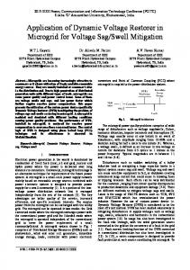
II. IDVR OPERATION A typical IDVR scheme is shown in Fig. 1[l]. Vs1
ZL1
Vb1 Vinj1
VL1 IL1
Load 1
Feeder 1-10kv
DVR1
CSI I
Common DC-link
DVR2 Vs2
Feeder 2-11kv
ZL2
CSI II
Vb2
VL2 IL2 Vinj2
Load 2
Fig.1.Schematic representation of the IDVR
The IDVR system consists of several DVRs in different feeders sharing a common dc link. A two-line IDVR system shown in Fig. 1 employs two DVRs connected to two different feeders originating from two grid substations. These two feeders could be of the same or different voltage level. When one of the DVRs compensates for voltage sag, the other DVR in IDVR system operates in power-flow control mode to replenish dc link energy storage which is depleted due to the real power taken by the DVR working in the voltage-sag compensation mode [8]. Propagation of voltage sags due to fault in the power system depends on many factors, such as voltage level and fault currents etc., Voltage sags in a transmission system are likely to propagate to larger electrical distance than that in a distribution system. Due to these factors and as the two feeders of the IDVR system in Fig. 1 are connected to two different grid substations, it is reasonable to assume that the voltage sag in Feeder 1 would have a lesser impact on Feeder 2. Therefore, the upstream generation-transmission system to the two feeders can be considered as two independent sources. These two sources are represented by the Thevenin’s equivalent impedances ZL1 and ZL2 connected to the buses B1 and B2 as in Fig. 1. ZL1 and ZL2 are calculated based on the fault level at B1 and B2. III.CURRENT SOURCE INVERTER The Voltage Source Inverter (VSI) is the dominant topology in reactive power control, with several VSI-based facts now operating in transmission systems. While most of the literature focuses on the VSI, but this paper focuses on CSI. Compared with the VSI, the CSI [9] topology offers a number of inherent advantages: including: 1) directly controlling the output current of inverter 2) implicit short-circuit protection, the output current being limited by the dc inductor 3) high converter reliability, due to the unidirectional nature of the switches and the inherent short-circuit protection 4) fast start-up, where no additional start-up rectifier is needed
ISSN : 0975-5462
Vol. 3 No. 8 August 2011
6455
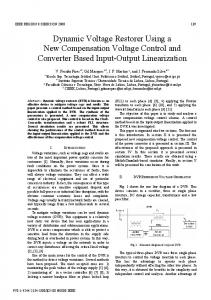
J.Singaravelan et al. / International Journal of Engineering Science and Technology (IJEST) 5) The common dc link current is ripple free 6) the magnitude of frequency varies by controlling the Id current using SCR 7) it act as the active filter 8) it act as the super conducting magnet energy storage[13]. Power electronic based FACTS or Custom Power devices [7] can be added to power transmission and distribution systems at strategic locations to improve system performance. One class of these devices uses temporary energy storage on a dc bus in the form of a capacitor. These devices can be used to control power flow on a transmission line by injecting a series voltage into the line or they can also support the voltage at a bus through shunt voltage injection. The addition of more substantial energy storage, such as a battery or capacitor bank makes these devices capable of maintaining voltage magnitude during a voltage sag or brief outage. An example of this is the Dynamic Voltage Restorer [8]. A SMES coil [4] could instead be incorporated onto the DC bus. Interfacing the coil to the ac system through a current source inverter results in a device that injects a controlled current with the ability to regulate ac voltage or power flow under normal conditions and supply when the power supply is off-line. If a dc/dc boost converter is used to interface to the coil, a voltage source inverter could be used to inject a voltage into the ac system. The figure 2 shows the structure of the Current Source Inverter.
Fig.2.Current source inverter structure
IV. SMES The voltage disturbance correction requires a certain amount of real and reactive power supply from the DVR. The DVR is required to inject active power into the distribution line during the period of compensation; the capacity of the energy storage unit can become a limiting factor in the voltage sag compensation process [8].The discovery of high temperature superconductivity [6] has sparked a great deal of interest in its application to the power area. One application, superconducting magnetic energy storage (SMES) coils can be used in many ways. They can used to damp dynamic swings on the ac system by absorbing or supplying real power in opposition to the oscillations. They can also be used for load leveling by charging them when excess generation is available and discharging them during high demand periods. Small SMES coils can act as an uninterruptible power supply to help loads ride through short outages and voltage sags [13]. One of the difficulties in adding a SMES coil to an ac System is the power converter interface needed to properly synchronize with the ac system and transfer energy in and Out of the coil. The power conditioning for a SMES coil has the added difficulty in that a wide range of voltages may be Necessary in addition to a wide range of currents. The voltage will need to reverse, although the current can stay unidirectional. Most power conversion options do better if either voltage or current has a somewhat smaller range of variation. Many power conversion options for SMES coils have been considered over the years, generally with the power conversion dedicated solely to the SMES coil [6].
ISSN : 0975-5462
Vol. 3 No. 8 August 2011
6456
J.Singaravelan et al. / International Journal of Engineering Science and Technology (IJEST)
Power Line B
Power Line A
SMES CONV
CONV
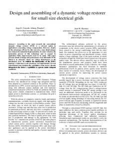
B Fig.3 Schematic diagram of SMES
The system is composed of two convertors connected to ac power transmission lines and a super conducting magnet connected in series in the DC section as shown in Fig.3. The voltage source inverter needs polarity reversal element to obtain reverse voltage where as in the current source inverter there is no need for the polarity reversal element. The system has higher freedom of control which enables to stabilize each part of AC line independently as well as to control power f low from one side to other. The power flow from one side to the other can be controlled. It follows that balancing of power flow in parallel lines or power line network system becomes possible, which leads to the effective use of the power line system [6]. V. SIMULATION RESULTS The circuit for line model without IDVR system with sag condition is shown in the figure 4 (a).
Fig.4 (a) Circuit line model without IDVR system with sag condition.
Simulated results of the without IDVR under sag condition
ISSN : 0975-5462
Vol. 3 No. 8 August 2011
6457
J.Singaravelan et al. / International Journal of Engineering Science and Technology (IJEST)
Fig.4 (b) Simulated results of voltage waveform across load 1 and load 2 without IDVR system in the line model.
The circuit for the line model with IDVR using VSI is shown in fig. 5 (a).
Fig.5 (a) Circuit for the line model with IDVR system using VSI.
The Fig.5 (b) shows the simulated results of voltage waveform across load 1 and load 2 with IDVR using VSI in the line model.
ISSN : 0975-5462
Vol. 3 No. 8 August 2011
6458
J.Singaravelan et al. / International Journal of Engineering Science and Technology (IJEST)
Fig.5 (b) Simulated results of voltage waveform across load 1 and load 2 with IDVR using VSI.
The FFT analysis for IDVR using VSI-source inverter with filter is shown in the figure 5 (c).
Fig.5 (c) FFT analysis for IDVR system using VSI.
The circuit for the line model with IDVR using CSI is shown in fig .6 (a).
ISSN : 0975-5462
Vol. 3 No. 8 August 2011
6459
J.Singaravelan et al. / International Journal of Engineering Science and Technology (IJEST)
Fig.6 (a) Circuit for the line model with IDVR system using CSI.
Simulated results of the IDVR at recovery from sag
ISSN : 0975-5462
Vol. 3 No. 8 August 2011
6460
J.Singaravelan et al. / International Journal of Engineering Science and Technology (IJEST)
Fig.6 (b). Simulated results of voltage waveforms across load 1, load 2 and IDVR using CSI.
The FFT Analysis for the IDVR using Current source inverter current with filter is shown in the figure 6 (c).
Fig.6 (c) FFT analysis for IDVR system using CSI.
ISSN : 0975-5462
Vol. 3 No. 8 August 2011
6461
J.Singaravelan et al. / International Journal of Engineering Science and Technology (IJEST)
VI. TABULATION Task or Area
IDVR using VSI
Fundamental ( 50 Hz) THD
1.129
IDVR using CSI 0.4569
24.60 %
4.51 %
The above results show the efficiency of the IDVR using Current Source Inverter with SMES. From the table, it is observed that the harmonic content has reduced with the use of CSI with SMES. It also shows that the IDVR using CSI with SMES does not require polarity reversal element.
VII. CONCLUSION This paper proposes the concept of IDVR, which is an economical approach to improve multiline power quality. The IDVR considered in this paper consists of several DVRs which are electrically far apart, connected to a common dc link (SMES). When one of the DVRs compensates voltage sag, the other DVRs are used to replenish the dc-link stored energy. The Interline Dynamic voltage restorer is used to improve voltage sags caused by increased loads. This paper presents a new IDVR topology derived from current-source inverter using SMES. Moreover the drawback of reverse voltage for the power flow in multi line for mitigating voltage sag can be overcomed by the use of SMES as a common DC link. The performances of proposed IDVR system and its controller were tested with simulations using Matlab / Simulink. It was observed that the IDVR compensates the disturbance caused by the sag effectively. VIII .REFERENCES [1] [2] [3] [4] [5] [6] [7]
Ghosh and G. Ledwich, “Compensation of distribution system voltage using DVR,” IEEE Trans. Power Del., vol. 17, no. 4, pp. 1030–1036,Oct. 2002. S. S. Choi, B. H. Li, and D. M. Vilathgamuwa, “Dynamic voltage restoration with minimum energy injection,” IEEE Trans. Power Syst., vol. 15, no.1, pp. 51–57, Feb. 2000. L. Gyugyi, K. K. Sen, and C. D. Schaude, “The interline power flow controller concept: A new approach to power flow management in transmission system,” IEEE Trans. Power Del., vol. 14, no. 3, pp. 1115–1123, Jul. 1999. B.K. Johnson and H.L. Hess” Incorporating SMES Coils into FACTS and Custom Power Devices. M. Vilathgamuwa, A. A. D. R. Perera, S. S. Choi, and K. J. Tseng, “Control of energy optimized dynamic voltage restorer,” in Proc. 25th Annu. Conf. IEEE Ind. Electron. Soc., 1999, vol. 2, pp. 873–878. H. Okada, T. Ezaki, K. Ogawa, etal., “Experimental Study of SMES system with DC Intertie for Power Line Stabilization,” IEEE Power Electronic Specialists Conference pp. 326-333, paper No. II D-5, April 1988.
.
ISSN : 0975-5462
Vol. 3 No. 8 August 2011
6462
J.Singaravelan et al. / International Journal of Engineering Science and Technology (IJEST)
[7] N.G.Hingorani,”Introducing custom power,” IEEE Spectrum, vol.32.no.6.p.41.1995. [8] D. Mahinda Vilathgamuwa, , H.and M. Wijekoon, and S. S. Choi, A Novel Technique to Compensate Voltage Sags in Multiline Distribution System—The Interline Dynamic Voltage Restorer V IEEE Trans on industrial electronics Vol. 53, No. 5, October 2006. [9] B. K. Bose, “Power Electronics and AC Drives”, Englewood Cliffs, NJ: Prentice-Hall, 1986. [10] N. Mohan, T. M. Underland, and W. P. Robbins, “Power Electronics”, 2nd ed. New York: Wiley. [11] Dong Shen and P. W. Lehn, “Modeling, Analysis, and Control of a Current Source Inverter-Based STATCOM”, IEEE Trans on Power Delivery, Vol. 17, No. 1, January 2002. [12] Sangshin Kwak, and Taehyung Kim, “An Integrated Current Source Inverter With Reactive and Harmonic Power Compensators”, IEEE Trans on Power Electronics, Vol. 24, NO. 2, February 2009. [13] R. H. Lasseter and S . G. Jalali, Dynamic Response of Power Conditioning Systems for Superconductive Magnetic Energy Storage IEEE Transactions on Energy Conversion, Vol. 6, No. 3, September 1991.
ISSN : 0975-5462
Vol. 3 No. 8 August 2011
6463