Sep 22, 2010 - AbstractâIn this paper, two new topologies are proposed for three-phase dynamic voltage restorers (DVRs). These topologies are based on ...
2676
IEEE TRANSACTIONS ON POWER DELIVERY, VOL. 25, NO. 4, OCTOBER 2010
Mitigation of Voltage Disturbances Using Dynamic Voltage Restorer Based on Direct Converters Ebrahim Babaei, Member, IEEE, Mohammad Farhadi Kangarlu, Student Member, IEEE, and Mehran Sabahi
Abstract—In this paper, two new topologies are proposed for three-phase dynamic voltage restorers (DVRs). These topologies are based on direct converters. The proposed topologies do not require dc-link energy storage elements. As a result, they have less volume, weight, and cost. They can also compensate long-time voltage sags and swells. The proposed DVRs can compensate several types of disturbances, such as voltage sags, swells, unbalances, harmonics, and flickers. Moreover, due to the fact that the compensation voltage for each phase is taken from all three phases, the proposed topologies can compensate one-phase outages. In the proposed topologies, three independent three-phase to single-phase direct converters are used. Each converter operates independently and, as a result, the proposed DVRs properly compensate unbalanced voltage sags and swells. The used converters can be constructed by four or six power switches. Depending on the structure of the used converters, the compensation ranges will be different. A new control method is also proposed for using direct ac/ac converters. The experimental and simulation results verify the capabilities of the proposed topologies in compensation of voltage distortions. Index Terms—Direct three-phase to single-phase converter, dynamic voltage restorer (DVR), flicker, harmonics elimination, voltage sag, voltage swell.
I. INTRODUCTION
V
OLTAGE disturbances are the most common powerquality (PQ) problem in industrial distribution systems. The voltage disturbances mainly encompass the voltage sags, swells, harmonics, unbalances, and flickers [1]. These disturbances can cause the malfunction of voltage-sensitive loads in factories, buildings, and hospitals [2] and sever process disruptions resulting in substantial economic and/or data losses [3]. Voltage sag is a momentary decrease in the rms ac voltage (10%–90% of the nominal voltage) at the power frequency of duration from 0.5 cycles to a few seconds [4]. Voltage sag is normally caused by short-circuit faults, such as a single-line-to-ground fault in a power system and by the startup of induction motors of large ratings [4]–[6]. Voltage swell is defined as a short duration increase in rms supply with an increase in voltage ranging from 1.1 p.u. to 1.8 p.u. of nominal supply [7]. The main reasons for voltage swells are switching large capacitors or the removal of large loads [8].
Manuscript received January 31, 2010; revised May 16, 2010; accepted June 12, 2010. Date of current version September 22, 2010. Paper no. TPWRD00054-2010. The authors are with the Faculty of Electrical and Computer Engineering, University of Tabriz, Tabriz 51664, Iran. Color versions of one or more of the figures in this paper are available online at http://ieeexplore.ieee.org. Digital Object Identifier 10.1109/TPWRD.2010.2054116
DVR is a power-electronic device [9]. The basic operation of DVR is to inject a voltage of required magnitude, phase angle, and frequency in series with a distribution feeder to maintain the desired amplitude and waveform for load voltage even when the voltage is unbalanced or distorted [9], [10]. Many topologies and control methods have been presented for DVRs. The presented topologies are categorized into two main groups. The first group of the presented topologies uses ac/dc/ac conversion. In these topologies, the required dc voltage is provided through a transformer from the grid (source side or load side) via a rectifier. In the second group of the presented topologies for DVRs, the required energy for compensation of voltage is taken from the dc capacitor or another energy storage element such as a double-layer capacitor, superconducting magnet or lead-acid battery via an inverter [11]. These types of topologies cannot compensate voltage sags and swells for a long time due to the limitation of the stored energy. In both groups of topologies, it is necessary to embed a large capacitor in the dc link. The cost of this dc-link capacitor is high and it results in high cost and limited applications of DVRs [12]. Therefore, some studies have been performed to reduce the size of the energy storage elements [2], [9], [13]. Also, a high-voltage DVR using multilevel topology has been presented in [5], [14]–[17]. There has been less attention to topologies of DVR that do not require any energy storage element. In [18], a zero energy sag corrector topology has been presented which is able to compensate balanced and unbalanced voltage sags without using a capacitor. This given topology is not able to compensate voltage swells, and its ability of harmonics mitigation has not been investigated. In [19], a topology for a single-phase DVR based on a direct ac/ac converter has been presented. In the presented topology, the compensation ranges for voltage sags and swells are restricted to 25% and 50%, respectively. In [20], a DVR based on an indirect matrix converter has been presented for balanced voltage sags compensation. This topology needs flywheel energy storage element and the capability of the topology in voltage swell compensation and harmonics and flicker elimination has not been investigated. Also, like the other topologies based on the energy-storage elements, it cannot compensate the voltage sags for a long time. Moreover, regulation and control of the flywheel speed is complicated. In [21], another matrix converter-based DVR has been presented. Two main problems of this topology are the high number of switches and very limited compensation range. In this paper, two new topologies for three-phase DVRs are proposed. The proposed topologies are based on direct ac/ac converters. As a result, there is no need for bulky and costly dc-link and energy storage elements. A new control method is
0885-8977/$26.00 © 2010 IEEE
BABAEI et al.: MITIGATION OF VOLTAGE DISTURBANCES USING DVR BASED ON DIRECT CONVERTERS
2677
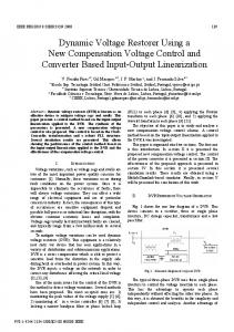
also proposed for the used converters in the proposed topologies. Then, the complete compensation ranges of voltage sags and swells are calculated. The simulation and experimental results are presented to clarify the capabilities of the proposed topologies in voltage restoration. II. PROPOSED TOPOLOGY Fig. 1 shows the schematic diagram of the proposed topologies. In each phase of the proposed topologies, a three-phase-tosingle-phase direct converter, an LC filter, a bypass switch, and ( for grid an injection transformer with a turns ratio of side) are used. The converters are directly connected to grid without a dc link. As mentioned, the conventional DVRs use the dc-link capacitor. Ratings of the dc-link capacitor bank of a voltage-source converter (VSC) may have a significant impact on the cost and physical size of a DVR. In conventional DVRs, the capacitor is sized for a specified ripple voltage. For reducing the ripple voltage on the dc link, the size of the capacitor should be increased. The penalty for making the capacitor large is cost and physical volume [22]. In the proposed topologies, the elimination of the dc link and energy-storage elements leads to a considerable reduction in cost and physical volume. The proposed topologies are able to compensate voltage disturbances for an unlimited time interval due to the fact that their required energy is directly provided through the grid. It is important to mention that this is not possible for topologies which are based on energy-storage elements because the energy storages have limited capacity. The proposed topologies are properly able to compensate unbalanced voltage sags and swells according to application of three independent three-phase-to-single-phase converters. As is obvious, the proposed topologies can compensate one phase outages because the compensation voltage in each phase is taken from all three phases of the source. Therefore, if one phase of the source voltage has lost, the corresponding phase of the load can be supplied from the other two phases. The other advantage of these topologies in comparison with the conventional DVRs is their ability to overcome the problem of restricting energy stored in a dc-link capacitor during fault occurrence. Each three-phase-to-single-phase converter in proposed topologies can be structured by four [Fig. 1(a)] or six [Fig. 1(b)] bidirectional power switches. There are several configurations for bidirectional switches [23]. In this paper, the common emitter configuration has been used. This configuration consists of two common emitter insulated-gate bipolar transistors (IGBTs) with two antiparallel diodes. As mentioned, the other way to present the proposed DVR is the application of three numbers of three-phase-to-single-phase converters with six bidirectional switches [Fig. 1(b)]. Here, the number of required switches is increased but for a constant turns ratio of injection transformers, the compensation range is wider than the first design. This issue is investigated in detail in the following sections. The control methods of used direct converters in proposed topologies are based on the pulsewidth-modulation (PWM) technique. Therefore, the generated waveform will face high-order harmonics due to high switching frequency. So the high-order harmonics should be filtered by an appropriate filter before being injected to the grid. This filter can be
Fig. 1. Proposed topologies. (a) First design. (b) Second design.
located on the converter side (as in Fig. 1) or on the grid side. Converter-side installation will have some advantages. In this condition, the filter is close to the harmonics generation source and, as a result, the filter operation will be better. In addition, the high-order harmonics currents will not enter the transformer and, as a result, the transformer ratings will not increase. Also, stress reduction this type of installation will be useful in on transformer windings and leads to an increase in the transformer lifetime. The used filter is a passive second-order LC filter with a damping resistor , which is connected in series to the filter inductor to stabilize the system in a more effective way and reduce transient state effects. The filtered voltages are injected to the grid through three . single-phase transformers with turns ratios of Considering Fig. 1, the following equation can be obtained: for
(1)
, and inj subscripts are used for the load, grid, and In (1), injected quantities, respectively. Also, subscript refers to the
2678
IEEE TRANSACTIONS ON POWER DELIVERY, VOL. 25, NO. 4, OCTOBER 2010
number of phases and its value is 1, 2, and 3 for the first, second, and third phases, respectively. Assuming sinusoidal waveforms, these voltages can be expressed as follows:
for
(2)
In the aforementioned equations, , and show the peak values of load, grid, and injected voltages, respectively. is the phase angle of the injected voltage and is defined as follows: for sag conditions for swell conditions
Fig. 2. Modulation method of the converters used in the first design.
TABLE I SWITCHES STATES AND v FOR DIFFERENT MODES OF OPERATION OF THE CONVERTERS USED IN THE FIRST DESIGN
(3)
are normally closed to short-cirThe bypass switches cuit the DVR. In the case of voltage distortion in the grid, the bypass switches are opened and the DVR starts the compensation process. III. PROPOSED CONTROL METHOD The control method of direct converters is based on the PWM technique. High-frequency switching between the highest and zero voltage levels is used in order to control the used converters in the proposed topologies. In order to explain the control . method, the switching frequency is considered as , each sampling period is During the th sampling period and time intervals in a way that divided to two for During the th sampling period, and valid in (4) and in the following inequalities: for
(4)
Table I indicates the states of the switches during these operational modes. The same procedure is used for second and third phases. Selecting the peak value in different instants would lead to an increase in the voltage transfer ratio of converters. Now, in and should be considered in a each sampling period, way that the desired voltage is provided in the converter output. is considered very high in comIf the switching frequency during parison with the grid frequency, the average of a sampling period will be constant and, as a result, the average can be calculated as folof the converter output voltage lows:
should be for
(6)
(5)
In the time interval, depending on the selected topology for the three-phase-to-single-phase converter, switches that cause zero voltage generation at the converter output side will be turned on. Similarly, in the time interval, the switches that cause the maximum positive output voltage generation should be turned on if the converter output voltage is in its positive half cycle and reversely, the switches that cause a maximum negative output voltage generation should be turned on if the converter output voltage is in its negative time half cycle. So during each sampling period, in the interval and in the time interval, the zero voltage level will show up in the converter output and this will continue for all sampling periods. The switching procedure of the direct converters in both designs has the same principle. It is noticeable that the used converters operate with phase voltages and line–line voltages in the first and second designs, respectively. Here, it is described for the first design. Fig. 2 shows the switching procedure for the first phase of the first design. As this figure shows, each cycle of the output voltage is divided into six modes of operation.
So, the converter output voltage in each period is generated by summing the pieces obtained in each sampling period which can be expressed as follows: (7) Considering (6), it is obvious that the combination of and zero voltage in and time intervals can provide the and time desired injected voltages. Using (4) and (6), intervals are obtained as follows:
for
(8)
is determined as (9) and (10) for the first and second designs, respectively for for (9)
BABAEI et al.: MITIGATION OF VOLTAGE DISTURBANCES USING DVR BASED ON DIRECT CONVERTERS
line for
line grid voltages and for
(10)
and conseWhen a voltage sag/swell occurs, it affects as (9) and (10). quently affects It is worth noting that the grid voltages are measured in the and, therefore, the front end of the source impedance voltage drop on the source impedance during compensation does not disturb the control system. and in (8), adopts discrete values as To calculate during each period of the output voltage. Regarding that the switching frequency is much higher than the and fundamental frequency, in each switching period can be assumed to be a constant value equal to their value in the beginning of that switching period. Therefore, in and each switching period, a constant value is obtained for . It is important to note that (8) is valid for any mathemat. In other words, the proposed control ical function of method can generate any expected voltage with arbitrary function. This is one of the most important advantages of the proposed control method. One possible application of this capability is the compensation of voltage distortion, such as voltage sags, swells, harmonics, and flickers. IV. COMPENSATION RANGES OF THE PROPOSED TOPOLOGIES In this section, the voltage sag and swell compensation ranges, which the proposed topologies can completely compensate, are calculated. The calculations are accomplished separately for these two conditions since the obtained range would differ for them. It is assumed that the phase shift from to is negligible and the phase shift from to is negligible. (the filtered voltage of the conThe relation between , and can be expressed by verter), for for
(11) (12)
is the peak value of the fundamental component of where the converter output voltage and is the phase angle of injected voltage and is defined as (3). In order to determine the output/input voltage transfer ratio , it is assumed that the switching frequency is very large in contrast with grid frequency. Therefore, the harmonics with lower frequencies or closer to grid frequency will not appear in the converter output side and the frequency of the converter output voltage can be considered independent from the grid frequency. Considering this assumption, just in each sampling period, the average of the sampled waveform should be equal to the expected output voltage value at the beginning of the same sampling period. In this case, the expected output voltage in each instant should fall between the grid voltage peak and the zero voltage level to verify the validity of (8). Therefore, in balanced grid voltages, the value of should satisfy the following inequality: for four switches converter for six switches converter
(13)
In sinusoidal conditions, (11)–(13) can be rewritten in terms of voltages amplitude as follows: for for for
(14) (15) (16)
In the voltage sag operation, it is assumed that grid and load voltages have the same phase angle. So the injected voltage should have the same phase with grid voltage. According to Fig. 1, the following equation can be written: for
(19)
Considering (16), (19) can be rewritten as follows: for The voltage sag percentage
(20)
is defined by (21)
It is important to note that under the voltage sag condition, to . Considering (20) the objective is to regulate and (21), the voltage sag percentage can be simplified to for
(22)
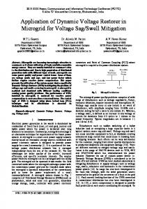
From the viewpoint of the converter, the maximum is obhas tained when the voltage transfer ratio of the converters a maximum value. Fig. 3 shows the variation of maximum versus . According to this figure, as increases, the compensable voltage sag for both topologies shown in Fig. 1 increases. Considering Fig. 3, the increase of a compensable range for the topology shown in Fig. 1(b) is more. Fig. 4 shows various plots as a function of for a range of specified worst case for voltage sag conditions and transformer turns ratio. B. Voltage Swell
In voltage sags and swells compensation operations, can be considered by
for
(18)
A. Voltage Sag
In (11), is the output/input voltage transfer ratio of the direct converters. Considering (11) and (12), the relation between and can be expressed as follows: for
2679
In the voltage swell operation, the injected voltage should have 180 phase difference from the grid voltage. According to Fig. 1, the following equation can be expressed as: (17)
for
(23)
2680
Fig. 3. Variation of maximum P
IEEE TRANSACTIONS ON POWER DELIVERY, VOL. 25, NO. 4, OCTOBER 2010
versus a.
as a function of q for a range of specified worst-case Fig. 6. Variation of P voltage swells and selected transformer turns ratio.
any voltage sag and swell are compensable by the varying voltage transfer ratio of the converters. V. SIMULATION AND EXPERIMENTAL RESULTS as a function of q for a range of specified worst-case Fig. 4. Variation of P voltage sags and selected transformer turns ratio.
Fig. 5. Variation of maximum P
versus a.
Considering (16), (23) can be simplified to for
(24)
is defined as follows:
The voltage swell percentage
(25) Under the voltage swell condition, the aim is to regulate to . Considering (24) and (25), the voltage swell percentage is simplified as follows: for
(26)
versus . Fig. 5 shows the variation of maximum This figure shows that as increases, the compensable voltage swell magnitude increases. Fig. 6 shows various plots for as a function of for a range of specified worst-case voltage swell conditions and transformer turns ratio. As Fig. 5 shows, if the turns ratio of the injection transformers for the 0.33, then the proposed topology in Fig. 1(b) is chosen proposed DVR can completely compensate the voltage swells with amplitudes from 0 to 100%. This value for the proposed 1. It means that for values equal or topology in Fig. 1(a) is larger than these values for both topologies, the voltage swell can be completely compensated. It should be noted that the output/input voltage transfer ratio of each converter can vary from zero to its maximum value continuously. So by selecting the proper constant turns ratio for the injection transformers,
In the following subsections, the simulation and experimental results of the proposed topologies are presented to illustrate their capabilities in voltage regulation on the load side. The load is an – load with 55-mH inductance and 65- resistance. In the 1 p.u. (220 V normal operation, grid voltage has rms) amplitude and 50-Hz frequency. The switching frequency of the converters is assumed to be 4 kHz. The used filters in the output of the converters are passive LC filters with a damping resistor. In order to design these filters, the following aspects are assumed. • The resonant frequency of filters is assumed to be about 10 times larger than the fundamental frequency of grid. • The voltage drop of the fundamental component is considered less than 5%. • The generated phase-angle difference in the filter is considered less than 0.1 radians for the fundamental component. • The proper transient state damping caused by the filter should be provided. Considering the aforementioned aspects, the filters compo8 mH, F and . nents values are The turns ratios of the injection transformers are considered 1. Choosing this turns ratio for the injection transformers, as the first design is able to compensate voltage sags with 33.33% and voltage swells with 100% magnitudes. The voltage sags and swells compensation ranges for the second design are 60% and 100%, respectively. A. Experimental Results To examine the performance of the proposed topologies and the control method, two prototypes of three-phase-to-singlephase DVRs based on proposed topologies are implemented. As mentioned, the common-emitter antiparallel IGBTs with a diode-pair arrangement have been used in this paper. The IGBTs of the prototypes are BUP306D with internal antiparallel diodes with voltage and current ratings equal to 1200 V and 20 A, respectively. To generate fault conditions (voltage sags and swells) in each phase of grid, four switches and a transformer with four taps were used. Each transformer consists of four taps and depending on the fact that which switch is closed, the desired fault is generated. The 89C52 microcontroller from ATMEL Co. has been used to generate the switching patterns according to the proposed control method. Fig. 7 shows the
BABAEI et al.: MITIGATION OF VOLTAGE DISTURBANCES USING DVR BASED ON DIRECT CONVERTERS
2681
Fig. 9. Experimental results for the first design. (a) Grid voltage. (b) Injected voltage. (c) Load voltage.
Fig. 10. Experimental results for the second design. (a) Grid voltage. (b) Injected voltage. (c) Load voltage. Fig. 7. Schematic diagram of the system.
Fig. 8. Photo of prototypes.
schematic diagram of the proposed topologies, their connections to the system, the control unit, and the circuit, which were used to create the fault conditions required to generate the voltage sags and swells. In all experimental measurements, the 1:100 probe is used. Fig. 8 shows a photo of the prototypes. Considering (1) and (12), the desired output voltage of the is calculated as follows: converters after filtering for
(27)
where is the instantaneous nominal load voltage. Neglecting the voltage drop and phase shift on the series branch of the filter, the low-frequency average of the output voltages of the converters are almost equal to the filtered output . Therefore, using (8) and (27), and voltage can be calculated as follows:
for
(28)
Equation (28) has been used to calculate the time intervals in the open-loop control system depicted in Fig. 7. In (28), is available via measurement, is the reference value is calculated from the meaof the load voltage, and using (9) and (10). sured To detect the voltage disturbances, the following criterion has been used: for
(29)
where is the peak value of the nominal load voltage. In (29), denotes the error between the nominal load and grid voltages and has a small value which, in prototype, has been assumed to be 0.02. If the value of is greater than 0.02, the voltage disturbances are detected and the bypass switches are opened. Then, the DVR starts the compensation process. The experimental studies are for showing the capability of the proposed DVRs in the compensation of voltage sags and swells. Initially, the system is in steady state and the voltage V. Then, for some periods, magnitude of the grid is faults occur. For the first design, 20% voltage sag and 30% voltage swell both occur for three periods. For the second design, 60% voltage sag and 30% voltage swell both occur for two periods. When the faults are cleared, the grid voltage recovers to its initial value. Considering (22) and (26), for the first design, it is clear that the converter voltage transfer ratios that are required for voltage sag and swell correction 0.25 and 0.23, under this specified condition are 1.5 and respectively. These values for second design are 0.23, respectively. As the converters’ voltage transfer ratios are adjusted, the converters’ output voltages are added to the load voltage. This process yields a compensated load V. Figs. 9–10 show the experimental voltage results of grid voltage , injected voltage , and load , respectively. As shown in these figures, during voltage normal operation, DVRs do not generate any voltage. During voltage sag and swell conditions, DVRs generate voltages with proper amplitudes and polarities and inject them to grid and consequently provide regulated voltage for the load. As a result, the load voltage will be stable and constant for all time intervals. B. Simulation Results The PSCAD/EMTDC software has been used for simulation. In all simulations, it is assumed that the all switches are ideal. One of the properties of the proposed topologies is flicker compensation. The voltage flicker can be considered as continuous voltage sags and swells. Considering that the proposed DVR can compensate voltage sags and swells, it can also compensate voltage flicker. The first simulation is to validate this capa-
2682
IEEE TRANSACTIONS ON POWER DELIVERY, VOL. 25, NO. 4, OCTOBER 2010
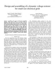
Fig. 12. Harmonic components. (a) Grid. (b) Load voltage.
Fig. 11. (a) Flicker elimination. (b) Harmonics and unbalances compensation: from top to bottom, the traces are grid voltage, converter output voltage (first phase), injected voltage, and load voltage.
bility. For this example, the first design has been used. Fig. 11(a) shows the simulation results of the voltage flicker compensation. As is obvious in this figure, grid voltage amplitude varies between 0.65 p.u. to 1.286 p.u. with a frequency of 10 Hz. The proposed topology operates in a way that the load does not sense any voltage flickers and operates in its normal condition. The second simulation study is for showing the capability of the proposed topologies in harmonics elimination and compensating the voltage unbalances. For this example, the second design has been used. It is assumed that grid voltage is unbalanced and significantly distorted as follows:
Fig. 11(b) shows the simulation results for the second simulation study. As shown in this figure, the proposed topology injects the required voltage to grid to stabilize the load voltage. The grid voltage is significantly unbalanced but the load voltage is balanced from the viewpoint of magnitudes and phase angles. It is very interesting to note that the proposed topologies and the control method are one of the particular methods that can generate the desired injected voltages from unbalanced and significantly distorted grid voltages. Fig. 12 shows the harmonic components of grid and load voltage. As can be seen, the peak value of the third harmonic in the grid voltage is 46.6 which is reduced to 12.6 on the load side. In the second phase, the peak value of the fifth harmonic is reduced from 78 to 32.5 and in the third phase, the peak value of the third harmonic is reduced from 31.1 to 3.84. The total harmonic distortion (THD) of grid voltages in the first, second, and third phases are 15%, 28%, and 9%, respectively. The THD of the load voltage mitigated to 4.6%, 12.2%, and 4.4% in the first,
Fig. 13. (a) Operation under first phase outage. (b) Performance of the DVR with different values for the turns ratio of the injection transformers. From top to bottom: traces are grid voltage, injected voltage, and load voltage.
second, and third phases, respectively. It is important to note that in this case, the proposed DVR not only mitigates voltage harmonics but it also compensates unbalances simultaneously. This is the reason why the THD of the load voltage in the second phase is relatively high. If the grid voltage has only harmonics and not unbalances, the amount of the THD of the load voltage will be considerably lower than the simulated condition. The third simulation study is for showing the capability of the proposed topologies in compensating one phase outage. For this example, the first design has been used. Fig. 13(a) shows the simulation results. Initially, the system is in steady state. From 0.02 s until 0.08 s, the first phase of the grid is outage and 0.08 s, the first phase of gird recovers to its initial then at condition. As the figure shows, the proposed topology injects the required voltage to grid to stabilize the load voltage. Considering Section IV, the compensation range of the proposed DVR depends on the injection transformers turns ratio. In order to show how the transformers turns ratio affects the operation of the DVR, a simulation is performed with three different values of transformers turns ratios. For this simulation, the second design is selected and at 0.02 s, 65% voltage sag is applied on the grid. Fig. 13(b) shows the effect of on the DVR performance. From the beginning of the simulation to 0.04 s, is considered to be 0.5. From 0.04 to 0.06 s, is 1 and from 0.06 s to 0.1 (end of the simulation), is 1.5. Considering (20) and Fig. 3, with these values for , the DVR can compensate voltage sags up to 42%, 60%, and 69%, respectively. Note that the applied voltage sag is greater than the compensable range 0.5 and 1. As a result, the DVR cannot completely with compensate the voltage sag. But with 1.5, the voltage sag is completely compensated.
BABAEI et al.: MITIGATION OF VOLTAGE DISTURBANCES USING DVR BASED ON DIRECT CONVERTERS
VI. CONCLUSION In this paper, two new topologies for three-phase DVRs are proposed. The proposed topologies are based on direct converters and, as a result, they do not require the dc link which is a basic element of conventional DVRs. The elimination of the dc link causes a great decrease in cost, weight, and volume of the DVRs and enables them to be presented in a package. The unbalanced voltage sags and swells are compensated appropriately due to the fact that in the proposed topologies, three independent three-phase-to-single-phase direct converters are used. The direct converters in the proposed topologies can consist of four or six power switches and while using each of them, the compensable range for constant values for the turns ratios of the injection transformers will differ. As shown by experimental and simulation results in different conditions, the proposed topologies are properly capable of compensating several types of voltage disturbances, such as voltage sags, swells, unbalances, harmonics, and flickers. The proposed topologies guarantee that the regulated voltage can be achieved for sensitive loads. REFERENCES [1] A. Elnady and M. M. A. Salama, “Mitigation of voltage disturbances using adaptive perceptron-based control algorithm,” IEEE Trans. Power Del., vol. 20, no. 1, pp. 309–318, Jan. 2005. [2] T. Jimichi, H. Fujita, and H. Akagi, “Design and experimentation of a dynamic voltage restorer capable of significantly reducing an energystorage element,” IEEE Trans. Ind. Appl., vol. 44, no. 3, pp. 817–825, May/Jun. 2008. [3] C. S. Lam, M. C. Wong, and Y. D. Han, “Voltage swell and overvoltage compensation with unidirectional power flow controlled dynamic voltage restorer,” IEEE Trans. Power Del., vol. 23, no. 4, pp. 2513–2521, Oct. 2008. [4] C. Zhan, A. Arulampalam, and N. Jenkins, “Four-wire dynamic voltage restorer based on a three-dimensional voltage space vector PWM algorithm,” IEEE Trans. Power Electron., vol. 18, no. 4, pp. 1093–1102, Jul. 2003. [5] B. Wang, G. Venkataramanan, and M. Illindala, “Operation and control of a dynamic voltage restorer using transformer coupled H-bridge converters,” IEEE Trans. Power Electron., vol. 21, no. 4, pp. 1053–1061, Jul. 2006. [6] P. R. Sánchez, E. Acha, J. E. O. Calderon, V. Feliu, and A. G. Cerrada, “A versatile control scheme for a dynamic voltage restorer for power-quality improvement,” IEEE Trans. Power Del., vol. 24, no. 1, pp. 277–284, Jan. 2009. [7] P. Boonchiam and N. Mithulananthan, “Dynamic control strategy in medium voltage DVR for mitigating voltage sags/swells,” in Proc. PST, 2006, pp. 1–5. [8] S. Sasitharan and M. K. Mishra, “Design of passive filter components for switching band controlled DVR,” in Proc. TENCON, 2006, pp. 1–6. [9] H. K. Al-Hadidi, A. M. Gole, and D. A. Jacobson, “A novel configuration for a cascade inverter-based dynamic voltage restorer with reduced energy storage requirements,” IEEE Trans. Power Del., vol. 23, no. 2, pp. 881–888, Apr. 2008. [10] Y. W. Li, D. M. Vilathgamuwa, F. Blaabjerg, and P. C. Loh, “Investigation and improvement of transient response of DVR at medium voltage level,” IEEE Trans. Ind. App., vol. 43, no. 5, pp. 1309–1319, Sep./Oct. 2007. [11] J. G. Nielsen and F. Blaabjerg, “A detailed comparison of system topologies for dynamic voltage restorers,” IEEE Trans. Ind. Appl., vol. 41, no. 5, pp. 1272–1280, Sep./Oct. 2005. [12] C. Meyer, R. W. De Doncker, Y. W. Li, and F. Blaabjerg, “Optimized control strategy for a medium-voltage DVR—Theoretical investigations and experimental results,” IEEE Trans. Power Electron., vol. 23, no. 6, pp. 2746–2754, Nov. 2008. [13] D. M. Vilathgamuwa, A. A. D. R. Perera, and S. S. Choi, “Voltage sag compensation with energy optimized dynamic voltage restorer,” IEEE Trans. Power Del., vol. 18, no. 3, pp. 928–936, Jul. 2003.
2683
[14] P. Roncero-Sanchez and E. Acha, “Dynamic voltage restorer based on flying capacitor multilevel converters operated by repetitive control,” IEEE Tran. Power Del., vol. 24, no. 2, pp. 951–960, Apr. 2009. [15] A. K. Sadigh, E. Babaei, S. H. Hosseini, and M. Farasat, “Dynamic voltage restorer based on stacked multicell converter,” in Proc. ISIEA, Malaysia, 2009, pp. 419–424. [16] E. Babaei, S. H. Hosseini, G. B. Gharehpetian, M. T. Haque, and M. Sabahi, “Reduction of dc voltage sources and switches in asymmetrical multilevel converters using a novel topology,” Elsevier J. Elect. Power Syst. Res., vol. 77, no. 8, pp. 1073–1085, Jun. 2007. [17] P. Chiang, D. M. Vilathgamuwa, S. K. Tang, and H. L. Long, “Multilevel dynamic voltage restorer,” IEEE Power Electron. Lett., vol. 2, no. 4, pp. 125–130, Dec. 2004. [18] A. Prasai and D. M. Divan, “Zero-energy sag correctors—Optimizing dynamic voltage restorers for industrial application,” IEEE Trans. Ind. Appl., vol. 44, no. 6, pp. 1777–1784, Nov./Dec. 2008. [19] J. Pérez, V. Cárdenas, L. Morán, and C. Núñez, “Single-phase ac-ac converter operating as a dynamic voltage restorer (DVR),” in Proc. IECON, 2006, pp. 1938–1943. [20] B. Wang and G. Venkataramanan, “Dynamic voltage restorer utilizing a matrix converter and flywheel energy storage,” IEEE Trans. Ind. Appl., vol. 45, no. 1, pp. 222–231, Jan./Feb. 2009. [21] E. Babaei and M. F. Kangarlu, “A new topology for dynamic voltage restorers without dc link,” in Proc. ISIEA, Malaysia, 2009, pp. 1009–1014. [22] D. Soto and T. C. Green, “A comparison of high-power converter topologies for the implementation of FACTS controllers,” IEEE Trans. Ind. Electron., vol. 49, no. 5, pp. 1072–1080, Oct. 2002. [23] E. Babaei, “A cascade multilevel converter topology with reduced number of switches,” IEEE Trans. Power Electron., vol. 23, no. 6, pp. 2657–2664, Nov. 2008. Ebrahim Babaei (M’10) was born in Ahar, Iran, in 1970. He received the B.S. degree in electronics engineering and the M.S. degree (Hons.) in electrical engineering from the Department of Engineering and the Ph.D. degree in electrical engineering from the Department of Electrical and Computer Engineering, University of Tabriz, Tabriz, Iran, in 1992, 2001, and 2007, respectively. In 2004, he joined the Faculty of Electrical and Computer Engineering, University of Tabriz. He has been Assistant Professor since 2007. His major fields of interest include the analysis and control of power-electronic converters, matrix converters and multilevel converters, flexible ac transmission systems devices, and power system dynamics.
Mohammad Farhadi Kangarlu (S’09) was born in Kangarlu, Iran, in 1987. He received the B.S. degree in electrical engineering from the University of Tabriz, Tabriz, Iran, in 2008, where he is currently pursuing the M.S. degree in electrical engineering (power electronics). His research interests include power quality, power-electronic converters, and custom power devices.
Mehran Sabahi was born in Tabriz, Iran, in 1968. He received the B.S. degree in electronic engineering from the University of Tabriz, Tabriz, in 1991, the M.S. degree in electrical engineering from Tehran University, Tehran, in 1994, and the Ph.D. degree in electrical engineering from University of Tabriz in 2009. In 2004, he joined the Faculty of Electrical and Computer Engineering, University of Tabriz, where he has been an Assistant Professor since 2009. His current research interests include power-electronic converters and power-electronic transformers.