MLE+ is a Matlab toolbox for co-simulation with the whole-building energy simulator EnergyPlus. ... Java socket library is used by MLE+ for communication with.
MLE+:
A
M ATLAB -E NERGY P LUS C O - SIMULATION I NTERFACE Truong X. Nghiem Automatic Control Laboratory Ecole Polytechnique F´ed´erale de Lausanne (EPFL), Switzerland
Contents 1
Introduction
1
2
Comparison with BCVTB
2
3
Loose Coupling Co-simulation
3
4
Installation 4.1 System Requirements . . . . . . . . . . . . . . . . . . . . . . . . . . . . . . . . . . . . . . 4.2 Install MLE+ . . . . . . . . . . . . . . . . . . . . . . . . . . . . . . . . . . . . . . . . . .
3 3 3
5
MLE+ Usage 5.1 General configuration for co-simulation with EnergyPlus 5.2 The BCVTB protocol . . . . . . . . . . . . . . . . . . . 5.3 Matlab functions and classes . . . . . . . . . . . . . . . 5.3.1 Start and stop co-simulation . . . . . . . . . . . 5.3.2 Send and receive data packets . . . . . . . . . . 5.3.3 Encode and decode data packets . . . . . . . . . 5.3.4 The mlepProcess class . . . . . . . . . . . . 5.4 Utility functions . . . . . . . . . . . . . . . . . . . . . . 5.5 Simulink library . . . . . . . . . . . . . . . . . . . . . .
3 4 4 4 5 5 5 5 6 6
6
Examples
. . . . . . . . .
. . . . . . . . .
. . . . . . . . .
. . . . . . . . .
. . . . . . . . .
. . . . . . . . .
. . . . . . . . .
. . . . . . . . .
. . . . . . . . .
. . . . . . . . .
. . . . . . . . .
. . . . . . . . .
. . . . . . . . .
. . . . . . . . .
. . . . . . . . .
. . . . . . . . .
. . . . . . . . .
. . . . . . . . .
7
A MLE+ License
1
. . . . . . . . .
10
Introduction
MLE+ is a Matlab toolbox for co-simulation with the whole-building energy simulator EnergyPlus. It is designed for engineers and researchers who are familiar with Matlab and Simulink and want to use these software tools in building energy simulation. MLE+ is particularly useful for:
1
• Controller design: the energy simulation is carried out by EnergyPlus while the controller is designed and implemented in Matlab or Simulink. • Simulation and data collection: a large number of simulations, with different scenarios, can be carried out and their data is collected, stored and processed in Matlab. The data can then be used for various purposes, e.g. for learning a model of the building system. • Simulation-based optimization: a non-linear optimizer, e.g. one in the Matlab’s Global Optimization Toolbox, can be used to find optimal parameters or control sequences of the building system, by considering the building as a black-box whose execution is performed by simulations by EnergyPlus. MLE+ toolbox provides a set of Matlab functions and classes, as well as a Simulink library, for performing co-simulation with EnergyPlus. The current version of MLE+, as of August 16, 2015, has been tested to work with EnergyPlus version 8.3.
2
Comparison with BCVTB
BCVTB (Building Controls Virtual Test Bed) is a software environment for coupling different simulation programs for distributed simulation. It is based on the Ptolemy II software environment and is developed at the Lawrence Berkeley National Laboratory. The co-simulation feature in EnergyPlus was originally developed for BCVTB, however the communication protocol is open and can be used by any program to perform co-simulation with EnergyPlus. MLE+ is an example of such programs. Although Matlab / Simulink can be coupled with EnergyPlus via BCVTB, its full functionality cannot be used because it is only called by BCVTB as a client. For example, interactive execution and debugging Matlab code are not possible. In fact, if the Matlab code or the Simulink model has an error, it is much more difficult to find and fix it with BCVTB than with MLE+ (which runs in the standard Matlab environment). Furthermore, for users who mostly work with Matlab / Simulink and have never used Ptolemy, learning a new environment as Ptolemy is time-consuming and might not be worthwhile. Advantages of BCVTB over MLE+ include: • It is always up-to-date with the co-simulation feature in EnergyPlus. • It can be used to couple other programs besides EnergyPlus and Matlab / Simulink, such as Modelica and Radiance. However, in the future, MLE+ will incorporate interfaces to these programs as well. • It is free, open-source and runs on Java. Note that MLE+ is also free and open-source, but it requires Matlab / Simulink which are commercial. Advantages of MLE+ over BCVTB include: • It takes full advantage of the Matlab / Simulink environment, including interactive simulation, code debugging, low-level co-simulation API (Application Programming Interface), code generation, and all available toolboxes. In other words, it integrates better with the Matlab / Simulink environment. • It is easier to extend MLE+, using Matlab programming, for specialized applications and functions. An example is large-scale optimization of building’s design parameters using parallel simulations 2
(with Matlab’s Parallel Computing Toolbox and Distributed Computing Server). Another example is a GUI for rapid development of building controllers, be it a simple PID controller or a complex Model Predictive Controller. • It is familiar to users who mainly use Matlab / Simulink, such as control engineers.
3
Loose Coupling Co-simulation
MLE+ implements a loose coupling co-simulation architecture between clients. Generally speaking, each simulator performs its local simulation and exchange their variables only once at every fixed synchronization time step. There is no iteration between clients at a time step or between any two consecutive time steps. The readers are referred to [1, 2, 3] for more details.
4 4.1
Installation System Requirements • MLE+ requires Matlab, and Simulink if you are going to use its Simulink library, of recent versions. It has been tested in Matlab versions R2009b through R2015a. • Java must be enabled in Matlab. Java socket library is used by MLE+ for communication with EnergyPlus. • EnergyPlus: MLE+ should work well with the current version of EnergyPlus, which was version 8.3 at the time this report was last updated. • BCVTB. MLE+ does not require BCVTB to run, however the ExternalInterface feature of EnergyPlus requires that BCVTB exists in the system.
4.2
Install MLE+
After all system requirements of MLE+ are satisfied, installation of MLE+ is simple. • First, download the compressed MLE+ distribution package and extract it to a directory. Let us call this directory . • Start Matlab and add to the search path, either by the GUI or by the following command: addpath(). • It is recommended to save the search path.
5
MLE+ Usage
MLE+ provides: 3
• A set of Matlab functions and classes for co-simulation with EnergyPlus from Matlab code. They all have prefix mlep. • A library of Simulink blocks for co-simulation with EnergyPlus from Simulink models. • Several utility functions. They all have prefix mlep.
5.1
General configuration for co-simulation with EnergyPlus
In order to perform co-simulation with EnergyPlus, certain configurations need to be done: the IDF model file may need to be instrumented to allow importing and exporting variables from and to external programs, and a configuration file named variables.cfg needs to be created to specify these input and output variables. For more details, refer to the BCVTB manual or the External Interface manual of EnergyPlus.
5.2
The BCVTB protocol
A special protocol is used to exchange data between co-simulation processes via sockets. Each packet is a text string that contains a sequence of numbers of the following format v f
nr ni nb t r1 r2 · · ·
where: • v is the version number (currently versions 1 and 2 are supported). • f is a flag: 0 if normal, 1 if simulation stopped, negative if error. • nr , ni , nb are the numbers of real variables, integer variables, and Boolean variables respectively. Currently, EnergyPlus requires that ni = 0 and nb = 0. • t is the current simulation time in seconds. • r1 , r2 , . . . are the values of the variables, starting with real ones, then integer ones, and finally Boolean ones. For more details, refer to the BCVTB manual.
5.3
Matlab functions and classes
Matlab functions in MLE+ can be classified into three groups: • Start and stop co-simulation with EnergyPlus. • Send and receive data packets to and from EnergyPlus. • Encode and decode data packets. This section only summarizes the functions and classes provided by MLE+. Detailed information should be found by reading the help text of the functions.
4
5.3.1
Start and stop co-simulation
• To start a new co-simulation session, use the function mlepCreate. Arguments include the path to the EnergyPlus executable, its command-line arguments, the BCVTB directory, and the host and port number for the communication socket. This function returns the status and the sockets created for communication. • When the co-simulation terminates, the communication sockets must be closed by the function mlepClose. Its arguments are the sockets returned by mlepCreate. 5.3.2
Send and receive data packets
• To read a packet from the other program, use the function mlepReadData. It returns the packet as a text string. • To send a packet to the other program, use the function mlepWriteData. The packet must be a text string. • Function mlepExchangeData can be used to send a packet to then immediately read a packet from the other program. 5.3.3
Encode and decode data packets
• To decode a packet, received from the other program as a text string, use the function mlepDecodePacket. It returns the flag, the simulation time, and the values as vectors. • To encode a data packet, use the function mlepEncodeData. Function mlepEncodeRealData can be used if only real values will be sent. Function mlepEncodeStatus is used if no values will be sent but the flag (e.g. to end a co-simulation session with flag 1, or to report an error with negative flags). 5.3.4
The mlepProcess class
The mlepProcess class wraps the above functions in an easy-to-use interface. Using this class for co-simulation is highly recommended. The properties of mlepProcess are (RW = read/write, RO = read-only): • version (RW, number): version number of the communication protocol (e.g. 2). • program (RW, string): path to the co-simulation program (e.g. path to EnergyPlus). • arguments (RW, string): command-line arguments to the co-simulation program. • workDir (RW, string): working directory (default is the current directory). • port (RW, number): communication socket port (default is 0, which means any available port). • host (RW, string): communication socket host (default is empty, which means the local host). 5
• bcvtbDir (RW, string): path to the directory of BCVTB. • configFile (RW, string): name of the socket configuration file. It must be ”socket.cfg” for EnergyPlus. • configFileWriteOnce (RW, bool): if true, the socket configuration file will only be written for the first time and whenever the server socket is changed. • acceptTimeout (RW, number): the number of seconds to wait for the co-simulation program to connect. • isRunning (RO, bool): true if the co-simulation is running. Following are the steps to use the mlepProcess class for co-simulation: 1. Create a new object of class mlepProcess by the command: ep = mlepProcess; Assign appropriate properties of ep, particularly the program path, the arguments, and the BCVTB path. 2. Start a co-simulation session by the command: [status, msg] = ep.start; Check that status is 0 to make sure that the co-simulation is started successfully. 3. Read packets using ep.read and write packets using ep.write. Packets can be decoded and encoded by appropriate functions (see section 5.3.3). If a non-zero flag is received, the simulation should be stopped. 4. Stop the co-simulation session by the command: ep.stop; Note that mlepProcess is a handle class, thus it is not necessary to re-assign the object whenever a method is called.
5.4
Utility functions • Function mlepWriteEPModel reads a template text file, replaces certain keywords in it with provided values, then writes the content to an output text file. The function can be used to generate IDF model files from template files by replacing certain parameters with specific values.
5.5
Simulink library
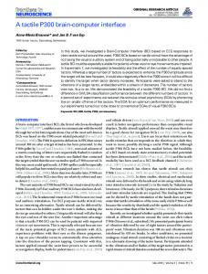
MLE+ provides a Simulink library to facilitate co-simulation with EnergyPlus in Simulink. Currently, the library contains only one block: the E+ Cosimulation block (Figure 1). This block implements co-simulation with EnergyPlus by allowing Simulink to exchange input and output data with it. When the Simulink
6
Figure 1: E+ Cosimulation Block. simulation starts, EnergyPlus is also started and will run in parallel with Simulink. They then exchange inputs and outputs via socket communication. When the simulation terminates, EnergyPlus will exit automatically. E+ Cosimulation block has one input port and three output ports: • The input is the real vector input to EnergyPlus. • The first output (flag) is the status of EnergyPlus. It is 0 if everything is normal, 1 if EnergyPlus has stopped its simulation, and negative if there was an error. Simulink should stop the simulation as soon as this flag is non-zero. • The second output (time) is the current simulation time of EnergyPlus, in seconds. • The last output (real) is the real vector output from EnergyPlus. Currently, integer and Boolean inputs and outputs are not supported. Figure 2 shows the parameter dialog box of the E+ Cosimulation block. These parameters are similar to the arguments of the function mlepCreate or the properties of the class mlepProcess. In addition, the number of real output variables must be specified (this is required by Simulink). E+ Cosimulation is a discrete-time block, so either its time-step is set to a positive value or the Simulink model is discrete-time.
6
Examples
MLE+ provides an example in which a building and HVAC model is simulated by EnergyPlus and a controller implemented in Simulink computes zone temperature set-points. This example is a reimplementation of a similar example in the BCVTB distribution. Figure 3 illustrates a Simulink model that implements this control system and a plotting window showing the simulation results. In the plot are the temperature set-points, the outdoor dry bulb temperature and the zone temperature for three days, with a 15-minute time-step. The same control system can be implemented in plain Matlab code instead of Simulink, using the mlepProcess class. Figure 4 shows the plots of simulation results computed by this Matlab script, which are the same as those in Figure 3. 7
Figure 2: Parameter dialog of E+ Cosimulation Block. All Matlab and Simulink example files are located in the sub-directory examples of the MLE+ distribution.
References [1] J. L. Hensen, “A comparison of coupled and de-coupled solutions for temperature and air flow in a building,” ASHRAE transactions, vol. 105, no. 2, pp. 962–969, 1999. [2] Z. J. Zhai and Q. Y. Chen, “Performance of coupled building energy and cfd simulations,” Energy and buildings, vol. 37, no. 4, pp. 333–344, 2005. [3] M. Trcka, M. Wetter, and J. Hensen, “Comparison of co-simulation approaches for building and hvac/r system simulation,” in Proceedings of the International IBPSA Conference, Beijing, China, 2007.
8
Figure 3: Simulink model simulation result.
Figure 4: Matlab script simulation result.
9
A
MLE+ License
MLE+ is open-source software. You are free to use it however you like. You may redistribute it. You may modify it to suit your need. If you redistribute MLE+ or derive your work from MLE+, you should give credit to the authors by including their names in your work and/or citing this report. You are encouraged to share any derivative work. Disclaimer: MLE+ IS DISTRIBUTED WITHOUT ANY WARRANTY. THE AUTHORS MAKE NO EXPRESS OR IMPLIED WARRANTIES OR CONDITIONS INCLUDING, WITHOUT LIMITATION, THE WARRANTIES OF MERCHANTABILITY OR FITNESS FOR A PARTICULAR PURPOSE WITH RESPECT TO THE SOFTWARE. IN NO EVENT SHALL THE AUTHORS BE LIABLE FOR ANY SPECIAL, INCIDENTAL, INDIRECT OR CONSEQUENTIAL DAMAGES CAUSED BY USING THE SOFTWARE.
10