increasingly difficult for companies to bring new products to the market within ... different application domains of embedded or/and software systems engineering areas. ...... shared resource is defined by its name, and its hosting processor and.
VTT CREATES BUSINESS FROM TECHNOLOGY Technology and market foresight • Strategic research • Product and service development • IPR and licensing • Assessments, testing, inspection, certification • Technology and innovation management • Technology partnership
692 693 694 695
696
697 698 699 700 701 702 703 704 705
Kimmo Keränen. Photonic module integration based on silicon, ceramic and plastic technologies. 2008. 101 p. + app. 70 p. Emilia Selinheimo. Tyrosinase and laccase as novel crosslinking tools for food biopolymers. 2008. 114 p. + app. 62 p. Olli-Pekka Puolitaival. Adapting model-based testing to agile context. 2008. 69 p. + app. 6 p. Minna Pikkarainen. Towards a Framework for Improving Software Development Process Mediated with CMMI Goals and Agile Practices. 2008. 119 p. + app. 193 p. Suvi T. Häkkinen. A functional genomics approach to the study of alkaloid biosynthesis and metabolism in Nicotiana tabacum and Hyoscyamus muticus cell cultures. 2008. 90 p. + app. 49 p. Riitta Partanen. Mobility and oxidative stability in plasticised food matrices. The role of water. 2008. 92 p. + app. 43 p. Mikko Karppinen. High bit-rate optical interconnects on printed wiring board. Micro-optics and hybrid integration. 2008. 162 p. Frej Wasastjerna. Using MCNP for fusion neutronics. 2008. 68 p. + app. 136 p. Teemu Reiman, Elina Pietikäinen & Pia Oedewald. Turvallisuuskulttuuri. Teoria ja arviointi. 2008. 106 s. Pekka Pursula. Analysis and Design of UHF and Millimetre Wave Radio Frequency Identification. 2008. 82 p. + app. 51 p. Leena Korkiala-Tanttu. Calculation method for permanent deformation of unbound pavement materials. 2008. 92 p. + app. 84 p. Lauri Kurki & Ralf Marbach. Radiative transfer studies and NextGeneration NIR probe prototype. 2009. 43 p. Anne Heikkilä. Multipoint-NIR-measurements in pharmaceutical powder applications. 2008. 60 p. Eila Ovaska, András Balogh, Sergio Campos, Adrian Noguero, András Pataricza, Kari Tiensyrjä & Josetxo Vicedo. Model and Quality Driven Embedded Systems Engineering. 2009. 208 p.
ISBN 978-951-38-7336-3 (URL: http://www.vtt.fi/publications/index.jsp) ISSN 1455-0849 (URL: http://www.vtt.fi/publications/index.jsp)
• • • VTT PUBLICATIONS 705 MODEL AND QUALITY DRIVEN EMBEDDED SYSTEMS ENGINEERING
VTT PUBLICATIONS
VTT PUBLICATIONS 705
Modeling Process Application service repository Application requirements
Application architecture design (2)
System requirements Specification (1)
Cross-domain architecture style
Platform requirements
System allocation/ configuration/ refinement (4)
Platform architecture design (3) Platform module library
Eila Ovaska, András Balogh, Sergio Campos, Adrian Noguero, András Pataricza, Kari Tiensyrjä & Josetxo Vicedo
Model and Quality Driven Embedded Systems Engineering
Reference architecture template
Qualit evalua (5)
VTT PUBLICATIONS 705
Model and Quality Driven Embedded Systems Engineering
Eila Ovaska & Kari Tiensyrjä VTT Technical Research Centre of Finland
Sergio Campos, Adrian Noguero & Josetxo Vicedo European Software Institute (ESI)
András Balogh & András Pataricza Budapest University of Technology and Economics (BME)
ISBN 978-951-38-7336-3 (URL: http://www.vtt.fi/publications/index.jsp) ISSN 1455-0849 (URL: http://www.vtt.fi/publications/index.jsp) Copyright © VTT 2009
JULKAISIJA – UTGIVARE – PUBLISHER VTT, Vuorimiehentie 5, PL 1000, 02044 VTT puh. vaihde 020 722 111, faksi 020 722 7001 VTT, Bergsmansvägen 5, PB 1000, 02044 VTT tel. växel 020 722 111, fax 020 722 7001 VTT Technical Research Centre of Finland, Vuorimiehentie 5, P.O. Box 1000, FI-02044 VTT, Finland phone internat. +358 20 722 111, fax +358 20 722 7001
Technical editing Leena Ukskoski Text preparing Tarja Haapalainen
Eila Ovaska, András Balogh, Sergio Campos, Adrian Noguero, András Pataricza, Kari Tiensyrjä & Josetxo Vicedo. Model and Quality Driven Embedded Systems Engineering. Espoo 2009. VTT Publications 705. 208 p. Keywords
methodology, modelling, evaluation, quality, embedded systems engineering
Abstract The world of embedded systems is broad and diverse, addressing a wide variety of application domains. Although technologically, the situation for embedded systems is still quite fragmented, platform-based engineering, reference designs and maturing system domains have effected great changes. However, the features of modern embedded systems are changing at such a rate that it is increasingly difficult for companies to bring new products to the market within acceptable time scales and still guarantee acceptable levels of operational quality. This report aims for its part to increase the convergence of views with regard to embedded systems technologies and engineering methods. The objective of this report is to introduce the methodology framework for model and quality driven embedded systems engineering. The framework is composed of three key artefacts, which provide the basis for building specific methodology instances. While instantiating this methodology framework, it has to be adapted to the needs and constraints of that specific application domain and development organisation. The first key artefact of the methodology framework is the process model, the Y-chart model. The second key artefact is the Unified Modelling Language (UML) adapted to embedded systems engineering with a specific profile. The third key artefact consists of a set of evaluation methods that have been selected for use in embedded system engineering. Within the conclusions, an initial integrated development environment is introduced for embedded systems engineering. The methods selected for the methodology framework have been validated in different application domains of embedded or/and software systems engineering areas.
3
Foreword This report is related to the European joint undertaking, called ARTEMIS (Advanced Research & Technology for EMbedded Intelligence and Systems), in the arena of embedded intelligence and systems engineering. The vision of ARTEMIS is that embedded systems will realise ambient intelligence in the physical objects of our everyday life and also in large-scale applications. By these means, ARTEMIS will increase the quality of people’s lives by making life healthier, more secure and by providing more comfort for Europe’s ageing population. Moreover, ARTEMIS aims to strengthen Europe’s position in embedded intelligence and systems and to attain world-class leadership in this area. This report introduces the first results of the methodology framework research made in one work package of the GENESYS (GENeric Embedded SYStem platform, FP7-213322) project [GENESYS 2008], which is an EU-funded effort to tackle the challenges of future embedded systems defined in ARTEMIS-SRA (http://www.artemis-sra.eu/). The work was done in collaboration with researchers from VTT, European Software Institute (ESI) and Budapest University of Technology and Economics (BME). I would like to thank Professor Veikko Seppänen from the University of Oulu for his insights and valuable comments for improving this report. I hope that readers in future ARTEMIS projects and more broadly in embedded systems engineering will find this report to be both interesting and useful. January 2009 Eila Ovaska Research Professor Leader of the Methodology and Tools work package in the GENESYS project
4
Contents Abstract ................................................................................................................3 Foreword ............................................................................................................... 4 Key Abbreviations ................................................................................................. 9 Part 1.
Introduction ........................................................................................... 12
1.1 Overview ........................................................................................................................... 12 1.2 Definitions ......................................................................................................................... 13 1.2.1 Methodology Framework........................................................................................ 13 1.2.2 Domain................................................................................................................... 14 1.2.3 The Cross-domain Style and Template ................................................................. 14 1.2.4 Embedded System................................................................................................. 15 1.2.5 Service Description ................................................................................................ 15 1.2.6 Service Modelling................................................................................................... 15 1.2.7 Ontology................................................................................................................. 16 1.2.8 Dependability ......................................................................................................... 16 1.2.8.1 Safety......................................................................................................... 17 1.2.8.2 Reliability.................................................................................................... 18 1.2.8.3 Availability .................................................................................................. 19 1.2.8.4 Security ...................................................................................................... 19 1.2.9 Scalability ............................................................................................................... 20 1.2.10 Performance ....................................................................................................... 20 1.2.11 Evolvability .......................................................................................................... 20 1.2.12 Quality of Service (QoS) ..................................................................................... 20 1.3 Principles of the Methodology Framework........................................................................ 21 1.3.1 Embedded Systems Engineering Process............................................................. 21 1.3.2 Model Driven Development.................................................................................... 22 1.3.3 Model Representation ............................................................................................ 22 1.3.4 Modelling Semantics .............................................................................................. 23 1.3.5 Formal Methods ..................................................................................................... 23 1.3.6 Quality and Non-Functional Properties .................................................................. 24 1.3.7 Support for Early V&V ............................................................................................ 24 1.3.8 Integrated Development Environment ................................................................... 24
5
Part 2.
Process Model ...................................................................................... 26
2.1 Overview ........................................................................................................................... 26 2.2 Process Phases ................................................................................................................ 28 2.2.1 System Requirements Specification ...................................................................... 28 2.2.2 Application Architecture Design ............................................................................. 29 2.2.3 Platform Architecture Design ................................................................................. 30 2.2.4 System Allocation / Configuration / Refinement..................................................... 31 2.2.5 Quality Evaluation .................................................................................................. 31 2.2.6 System Realization ................................................................................................ 32 2.3 Artefacts............................................................................................................................ 33
Part 3.
Modelling and Evaluation...................................................................... 35
3.1 System Requirements Specification ................................................................................. 35 3.1.1 Requirements Elicitation ........................................................................................ 37 3.1.2 Requirements Analysis and Documentation .......................................................... 38 3.1.3 Requirements Traceability ..................................................................................... 41 3.2 Architecture Design........................................................................................................... 41 3.2.1 Selection of Modelling Languages ......................................................................... 42 3.2.2 Architectural Elements ........................................................................................... 46 3.2.3 Architectural Views, Models and Transformations ................................................. 47 3.3 Application Architecture Design ........................................................................................ 48 3.3.1 Structural View ....................................................................................................... 50 3.3.2 Syntactical View ..................................................................................................... 55 3.3.3 Behaviour View ...................................................................................................... 58 3.3.4 Semantic View ....................................................................................................... 62 3.4 Platform Architecture Design ............................................................................................ 63 3.4.1 Structural View ....................................................................................................... 65 3.4.1.1 MARTE GRM Concepts for Execution Platform Modelling ........................ 66 3.4.1.2 Modelling Processing Units and Tasks ...................................................... 68 3.4.1.3 Modelling Shared Resources..................................................................... 69 3.4.1.4 Modelling Variables and Shared Memory .................................................. 70 3.4.1.5 Modelling Communication Resources ....................................................... 70 3.4.1.6 Modelling Platform Black-boxes................................................................. 71 3.4.1.7 Modelling Timing Resources...................................................................... 72 3.4.1.8 Further Refining Platform Structural Models.............................................. 73 3.4.2 Behaviour View ...................................................................................................... 73 3.4.3 Code View.............................................................................................................. 76 3.5 Platform Module Library.................................................................................................... 77 3.6 Integration and Development of Platform Services .......................................................... 79 3.6.1 Interfacing with Platform Services.......................................................................... 79 3.6.2 Describing the Behaviour of the Services .............................................................. 80 3.6.3 Design Process for New Platform Services ........................................................... 80 3.7 System Allocation / Configuration / Refinement ............................................................... 81 3.7.1 Schedulability Analysis and Simulation.................................................................. 83 3.7.1.1 Scheduling View ........................................................................................ 83 3.7.1.2 Analysis and Simulation Tools ................................................................... 87
6
3.7.1.3 Concepts of Scheduling View .................................................................... 95 3.8 Quality Evaluation ............................................................................................................. 97 3.8.1 Performance Evaluation......................................................................................... 98 3.8.1.1 Pre-requisites........................................................................................... 100 3.8.1.2 System Requirements Definition.............................................................. 100 3.8.1.3 Application Architecture Design ............................................................... 101 3.8.1.4 Platform Architecture Design ................................................................... 102 3.8.1.5 System Allocation / Configuration / Refinement....................................... 103 3.8.2 Performance Evaluation Methods ........................................................................ 104 3.8.2.1 Performance Evaluation of Software Architecture ................................... 105 3.8.2.2 Application-platform Performance Evaluation.......................................... 108 3.8.3 Power/Energy Efficiency Evaluation .................................................................... 117 3.8.3.1 Pre-requisites........................................................................................... 118 3.8.3.2 System Requirements Definition.............................................................. 118 3.8.3.3 Application Architecture Design ............................................................... 119 3.8.3.4 Platform Architecture Design ................................................................... 120 3.8.3.5 System Allocation / Configuration / Refinement....................................... 120 3.8.4 Power/Energy Evaluation Techniques ................................................................. 120 3.8.4.1 Power Analysis in a Multiprocessor Simulation Platform ......................... 121 3.8.5 Reliability and Availability Evaluation................................................................... 124 3.8.5.1 System Requirements Specification ........................................................ 125 3.8.5.2 Architecture Design.................................................................................. 128 3.8.6 Reliability and Availability Evaluation Methods .................................................... 130 3.8.6.1 Reliability Prediction of Component Based Architectures........................ 130 3.8.6.2 Reliability Evaluation in Model Driven Development................................ 132 3.8.6.3 Reliability and Availability Prediction and Testing.................................... 135 3.8.6.4 Commercial Reliability Analysis Tools ..................................................... 136 3.8.7 Safety Analysis..................................................................................................... 137 3.8.7.1 Safety Analysis Techniques..................................................................... 138 3.8.7.2 GENESYS Safety Certification Approach ................................................ 143 3.8.7.3 Prerequisites ............................................................................................ 145 3.8.7.4 System Requirements Specification ........................................................ 146 3.8.7.5 Fault and Hazard Modelling ..................................................................... 148 3.8.8 Safety Analysis Methods (PSSA Stage) .............................................................. 150 3.8.8.1 Hip-HOPS Method ................................................................................... 151 3.8.8.2 Model Checking Method .......................................................................... 155 3.8.8.3 Commercial Safety Analysis Tools .......................................................... 158 3.8.9 Composability Evaluation..................................................................................... 158 3.8.9.1 Model-Based Evaluation .......................................................................... 160 3.8.9.2 Component Based Evaluation ................................................................. 163 3.8.10 Evolvability Evaluation ...................................................................................... 166 3.8.10.1 Adaptability Evaluation............................................................................. 167 3.8.10.2 Extensibility Evaluation ............................................................................ 170 3.8.10.3 Maintainability, Flexibility and Modifiability Evaluation............................. 172 3.8.10.4 Trade-off Analysis .................................................................................... 177 3.8.11 Summary of Quality Evaluation ........................................................................ 179
7
Part 4.
Conclusions and Future Work ............................................................ 181
4.1 Overview ......................................................................................................................... 181 4.2 Integrated Development Environment ............................................................................ 181 4.2.1 Extra Requirements ............................................................................................. 181 4.2.1.1 Support for Multiple Modelling Languages............................................... 181 4.2.1.2 Collaborative Development Support ........................................................ 182 4.2.1.3 Open, Extensible Design Environment .................................................... 182 4.2.2 Integrated Design Environment ........................................................................... 182 4.2.2.1 Versioning Artefact Storage ..................................................................... 185 4.2.2.2 Artefact Catalogue and Access Rights Management .............................. 185 4.2.2.3 Query Services ........................................................................................ 186 4.2.2.4 Navigation and Traceability...................................................................... 186 4.2.2.5 Model Transformation Engine.................................................................. 186 4.2.2.6 Workflow Orchestration Layer.................................................................. 187 4.2.2.7 Client Communication and Event Dispatching......................................... 187 4.2.3 Model Transformations ........................................................................................ 187 4.2.3.1 From requirements to PIM and PM.......................................................... 188 4.2.3.2 PIM-related Transformations ................................................................... 188 4.2.3.3 Import from Model Libraries / Repositories .............................................. 189 4.2.3.4 System Allocation / Configuration / Refinement....................................... 189 4.2.3.5 PSM to Analysis Transformations............................................................ 190 4.2.3.6 Source and Configuration Files Generation............................................. 191 4.2.4 Available Technologies for the Tool Development............................................... 191 4.2.4.1 Available Technologies ............................................................................ 191 4.2.4.2 Research and Development Items........................................................... 192 4.3 Evaluating Methodology Framework............................................................................... 193 4.4 Lessons Learned ............................................................................................................ 197
References........................................................................................................ 199
8
Key Abbreviations API
Application Programming Interface
ARTEMIS
Advance Research & Technology for Embedded Intelligence and Systems
BIP
Behaviour, Interaction, Priority
BMSC
Basic Message Sequence Chart
CCA
Common Cause Analysis
CCS
Cruise Control System
COTS
Components off-the-shelf
CP
Configuration and Planning
CPU
Central Processing Unit
DAS
Distributed Application Subsystem
DM
Diagnostics and Maintenance
DSL
Domain Specific Language
DSML
Domain Specific Modeling Language
EMF
Eclipse Modeling Framework
FES
Failure Effects Summary
FHA
Functional Hazard Assessment
FLM
Failure Logic Modeling
FM
Formal Method
FMEA
Failure Modes and Effects Analysis
FMEA
Failure Modes and Effects Analysis
FMECA
Failure Modes Effect (and Criticality) Analysis
FSM
Finite State Machine 9
FTA
Fault Tree Analysis
GCM
Generic Component Model
GENESYS
GENeric Embedded SYStem platform
GQAM
Generic Quantitative Analysis Modeling
GRM
Generic Resource Modeling
HALM
High Level Application Modeling
HMSC
High level Message Sequence Chart
HRM
Hardware Resources Modeling
HW
Hardware
IP
Intelligent Property
IPC
Inter Process Communication
LI
Local Interface
LIF
Linking Interface
LQN
Layered Queuing Network
LTS
Labelled Transition System
LTSA
Labelled Transition System Analyser
MARTE
Modelling and Analysis of Real-time and Embedded systems
MDA
Model Driven Architecture
MDR
Meta Data Repository
MPSoC
Multi-Processor System- on-Chip
MSC
Message Sequence Chart
MTBF
Mean Time Between Failure
MTTCF
Mean Time To Critical Failure
MTTF
Mean Time To Failure
MTTR
Mean Time To Repair
NFP
Non-Functional Property
OS
Operating System
OWL
Web Ontology Language
OWL-S
Web Ontology Language for Services
PAM
Performance Analysis Modeling
PHA
Preliminary Hazard Assessment
10
PIM
Platform Independent Model
PM
Platform Model
PoF
Probability of Failure
PSM
Platform Specific Model
PSSA
Preliminary System Safety Assessment
QA
Quality Attribute
QoS
Quality of Service
RAM
Requirements Engineering Abstraction Model
RAP
Reliability and Availability Prediction
SAM
Schedulability Analysis Modeling
SIL
Safety Integrity Level
SRM
Software Resources Modeling
SW
Software
SysML
Systems Modeling Language
TCP
Transmission Control Protocol
TET
Trustworthiness Evaluation and Testing
UML
Unified Modeling Language
V&V
Verification and Validation
VPM
Visual and Precise Metamodelling
WSDL
Web Service Description Language
WSMO
Web Service Modelling Ontology
XMI
XML Metadata Interchange
XML
eXtensible Markup Language
XSLT
Extensible Stylesheet Language Transformations
11
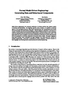
Part 1. Introduction 1.1 Overview This report defines a methodology framework for embedded systems engineering including 1) the process model, 2) a specific modelling approach for embedded system engineering and 3) a selected set of evaluation methods that helps in early evaluation of a system’s quality. Furthermore, an integrated development environment is introduced for assisting in the smooth design of embedded systems. The objective of this report is to define a methodology framework for developing embedded systems according to the cross-domain architecture style and the reference architecture template, which were defined at the same time with this methodology framework in the GENESYS project [GENESYS 2008]. The term ‘cross-domain’ refers to different industrial fields, such as automotive, avionics and mobile phones. The methodology framework is composed of three main parts, which provide the basis for building specific methodology instances. The first part of the methodology framework (Figure 1) is the modelling process. It is based on the Y-chart model including the ordered phases with input, output and trigger definitions for each phase. The second part is the primary modelling language; the Unified Modelling Language (UML), adapted to embedded systems engineering with the MARTE (Modelling and Analysis of Real-time and Embedded systems) profile [OMG 2008]. Although other modelling languages are allowed, proper model transformations between the primary language and specific ones are to be supported by the provider of that specific language. For each modelling phase, a set of architectural views are defined. The use of specific views depends on the selected quality evaluation methods and tools, which are defined in the third part as an extensive set of evaluation methods and their supporting tools. Guidelines and examples are given by illustrating how to use the UML-MARTE modelling language. 12
Part 1. Introduction
Example
Quidelines
Quality Evaluation Methods
Specific Views
Architecture Views
Requirements Views
Modeling Languages
Genesys Methodology Framework
Model Transformations
Others
Safety
Reliability & Availability
Quality Evaluation Tools Peformance
Scedulability Analysis & Simulation
Modeling Tools
Modelling Process
Integrated Development Environment
Figure 1. The Methodology Framework.
In the conclusion part, a tool environment is introduced through which the methods and techniques selected for the architecture modelling and evaluation phases are integrated and adapted together to support a smooth design flow. The integrated development environment defines the development infrastructure that allows tracing modelling artefacts between process phases, a set of model transformations for extending modelling capabilities and support for adapting commercial and open source tools for executing the selected instance of the methodology framework.
1.2 Definitions 1.2.1
Methodology Framework
The methodology framework provides support for the definition of an engineering process which is composed of suitable (design, evaluation, testing etc.) methods, techniques and tools. Methodology defines the process, methods and tools to be used in the development of different types of embedded systems, i.e. the methodology is an instance of the methodology framework.
13
Part 1. Introduction
The methodology framework is intended for the development of embedded systems and products by developing and integrating components and services according to the specified reference architecture defined by a cross-domain architectural style and a reference architecture template. 1.2.2
Domain
The term ‘domain’ differs in meaning according to context. In general, however, it refers to the field of study, e.g., the domain of computer science, the field of interest, e.g., embedded system engineering, or the field of applications, e.g. automotive industry. 1.2.3
The Cross-domain Style and Template
The cross-domain architectural style defines a set of principles for designing GENESYS architecture [GENESYS 2008]. These principles are classified according to seven categories. The last one concerns system design and evolution and is relevant from the methodology development point of view: • model-based design is to be adopted, • name space design is to be followed; separate namespaces for the logical and physical system architecture, • modular certification in order to reduce cost and to focus on quality assurance effort for the most critical parts of a system, and • legacy integration is to be supported and technology obsolescence to be avoided by separation of designs from implementation technologies. The reference architecture template [GENESYS 2008] describes a set of core and optional services which can be used as such in the system development. The core services are applicable for all application domains while optional services are domain specific. The cross-domain architecture style and the reference template will be published in a book in late 2009. The cross-domain architecture style and the reference architecture are not the topics of this report but need to be understood because the methodology framework aims to support the development of embedded systems which follow the cross-domain architecture style and reference architecture template, rather than any kind of embedded systems engineering.
14
Part 1. Introduction
1.2.4
Embedded System
According to [ES 2008] embedded systems can be characterized as follows: •
Embedded systems are designed to do some specific task, rather than be a general-purpose computer for multiple tasks. Some also have real-time performance constraints that must be met, for reasons such as safety and usability; others may have low or no performance requirements, allowing the system hardware to be simplified to reduce costs.
•
Embedded systems are not always standalone devices. Many embedded systems consist of small, computerized parts within a larger device that serves a more general purpose. For example, an embedded system in an automobile provides a specific function as a subsystem of the car itself.
•
The program instructions written for embedded systems are stored in read-only memory or Flash memory chips. Embedded systems run with limited computer hardware resources: little memory, small or non-existent keyboards and/or screens.
1.2.5
Service Description
Service description is an explicit and detailed definition supported by a low (but not detailed) level process model. The textual definition is augmented by machine-readable semantic information about the service which facilitates the service mediation and consistency checking of the architecture. Service description includes a set of quality indicators and non-functional properties (e.g. power consumption, timing, availability, etc.). Service description defines a link to the information model showing what information/functionality the “Service” owns and which information/functionality, owned by other “Services”, it references. Service description provides a list of known other “Services” that depend upon its function or information and the documentation of their requirements. 1.2.6
Service Modelling
Service modelling produces a service description by exploiting generic graphical modelling languages, such as Unified Modelling Language (UML), and/or
15
Part 1. Introduction
textual notations such as Web Services Description Language (WSDL) and Web Ontology Language for services (OWL-S). 1.2.7
Ontology
Ontology is a shared knowledge standard or a knowledge model defining the primitive concepts, relations, rules, and their instances comprising a relevant knowledge topic. Ontology is used for capturing, structuring, and enlarging explicit and tacit knowledge across people, organizations, systems, and software services. 1.2.8
Dependability
Dependability is the collective term used to describe availability performance and its influencing factors (Figure 2): reliability, maintainability and maintenance support for performance. [IEC IEV 2008]. The IFIP 10.4 Working Group on Dependable Computing and Fault Tolerance defines dependability as “the trustworthiness of a computing system which allows reliance to be justifiably placed on the service it delivers”. [IFIP WG 10.4 2008]. Basically, Dependability of a computing system is the ability to deliver service that can justifiably be trusted. The service delivered by a system is its behaviour as it is perceived by its user(s); a user is another system (physical, human) that interacts with the former at the service interface. The function of a system is what the system is intended to do, and is described by the functional specification. Correct service is delivered when the service implements the system function. A system failure is an event that occurs when the delivered service deviates from correct service. A failure is thus a transition from correct service to incorrect service, i.e., to not implementing the system function. The delivery of incorrect service is defined as a system outage. Based on the definition of failure, an alternate definition of dependability, which complements the initial definition in providing a criterion for adjudicating whether the delivered service can be trusted or not can be given thus: the ability of a system to avoid failures that are more frequent or more severe, and outage durations that are longer, than is acceptable to the user(s).
16
Part 1. Introduction
DEPENDABILITY ATTRIBUTES
Reliability
Availability
Safety
Security
Figure 2. Dependability is a general concept that manages different attributes [see Dependability Attributes, http://en.wikipedia.org/wiki/Dependability]
1.2.8.1
Safety
Safety describes the absence of catastrophic environmental consequences. The Safety S(t) of a system can be expressed as: S(t) = Prob (system is fully functioning or has failed in a manner that causes no harm in [o,t]). A metric for safety S(t) is MTTCF, the Mean Time to Critical Failure, defined similarly to MTTF and normally expressed in hours. Closely related to the concept of safety design requirement is the Safety Integrity Level (SIL), defined as a relative level of risk-reduction provided by a safety function, or to specify a target level of risk reduction. Four SIL levels are defined in (Table 1), with SIL4 being the most dependable and SIL1 being the least. A SIL is determined based on a number of quantitative factors in combination with qualitative factors such as development process and safety life cycle management. The requirements for a given SIL are not consistent among all of the functional safety standards. Table 1. Safety Integrity Levels.
17
Part 1. Introduction
Different standards are defined according to application domains. The international standard IEC 61508 defines SIL using requirements grouped into two broad categories: hardware safety integrity and systematic safety integrity. A device or system must meet the requirements for both categories to achieve a given SIL. The SIL requirements for hardware safety integrity are based on a probabilistic analysis of the device. To achieve a given SIL, the device must have less than the specified probability of dangerous failure and have greater than the specified safe failure fraction. These failure probabilities are calculated by performing a Failure Modes and Effects Analysis (FMEA). The actual targets required vary depending on the likelihood of demand, the complexity of the device(s), and the types of redundancy used. Electric and electronic devices can be certified for use in functional safety applications according to IEC 61508, providing application developers the evidence required to demonstrate that the application including the device is also compliant. Specific adaptations of standard IEC 61508 are IEC 61511, used in the petrochemical and hazardous chemical industries and EN 50128, EN 50129 in rail domain. Other standards are ISO/WD 26262 in the automotive domain and DO-178B for aeronautics systems. 1.2.8.2
Reliability
Reliability – probability of correct service for a given duration of time. The Reliability S(t) of a system can be expressed as: S(t) = Prob (system is fully functioning or has failed in a manner that does cause no harm in [o,t]). [see http://en.wikipedia.org/wiki/Reliability_engineering#Reliability_theory]. Reliability is closely related to safety: it is the length of time the system must be able to operate without the safety aspects being jeopardised. For this reason, reliability and safety are often treated together, and usually, a trade-off must be made between them. One way to change reliability/safety can be by adding redundant systems, or adding components to verify the correct operation of the basic functionality. The net result of redundancy is that safety increases (more error situations can be detected and trapped/reported), but that reliability decreases (the redundant system itself can fail as well).
18
Part 1. Introduction
1.2.8.3
Availability
Availability – probability of readiness for correct service. Availability is the measure of dependability with respect to readiness for usage. In applications where short periods of downtime are acceptable, they must be minimized in order to maximize the availability of the service that is delivered (closely related to the Quality of Service). A number of statistical methods, based on the history of the system, have proven their value on the hardware level. For software, however, the stochastic approach is still being investigated and/or developed for the most part. Depending on how redundancy is built into the system, there will be an impact on availability. Cumulative downtime or uptime over an extended period of time (possibly expressed as a percentage) is the typical measures used to describe this aspect. Also, the number of failures per (extended) period of time (e.g. a year) can provide valuable information, or even better, the mean time of occurrence of the first failure. These are statistical metrics, which can be drawn from historic data, if available. At this time, it makes sense to distinguish between repairable systems (either subject to maintenance and/or failing systems can be replaced entirely) and nonrepairable systems (inaccessible systems like satellites). For the latter ones, cumulative up or downtime has little or no meaning. If a failure causes the system to go down, then it becomes practically impossible to get it operational again. The Availability A(t) of a system can be expressed as: A(t) = Prob (system is fully functioning at time t). A metric for the average is A (t) = MTTF / MTTF + MTTR where MTTR = 1/t and t is the constant repair rate. A(t) is normally expressed in %. [http://en.wikipedia.org/wiki/Availability] 1.2.8.4
Security
Security is the condition of being protected against danger, loss, and criminals. Security is a concept related to safety and reliability. [http://en.wikipedia.org/ wiki/Security#Types_of_security]. Information security attributes define the aspects of a system that security is formed, drawing from the composite notion of security as the combination of the following properties: 1) confidentiality, i.e. the prevention of unauthorized disclosure of information; 2) integrity, i.e. the prevention of unauthorized modification (amendment or deletion) of information
19
Part 1. Introduction
(including accountability and non-repudiation as subcategories); and 3) availability, i.e. the prevention of unauthorized withholding of information. [http://en.wikipedia.org/wiki/Information_security]. 1.2.9
Scalability
A system or technique is called scalable if for increasing size of the system or problem, the complexity is reasonably bounded (i.e. linear or polynomial). 1.2.10 Performance Performance has three dimensions: Responsiveness measured as response time and throughput; Resource utilization categorized into processing units, memory, communication, energy and peripherals; and Scalability measured as the ability of the system to continue its responsiveness objectives as the demand for functions varies. 1.2.11 Evolvability Evolvability refers to the ability of a system to persist in the face of changing conditions. The changing conditions to be taken into account in the GENESYS methodology specification are those changes that may happen during the design time, i.e. while designing the platform architecture (i.e. defining variability) and applying the platform architecture to product development (i.e. reusability, integrability, extensibility, managing variability). 1.2.12 Quality of Service (QoS) Quality of service refers to the non-functional and quality properties of services at different levels. QoS is the degree to which a service meets its quality requirements and end-user needs (i.e. availability, reliability and performance). QoS quantifies the service fitness based on the collective behaviour of composite services.
20
Part 1. Introduction
1.3 Principles of the Methodology Framework This section describes eight principles that the methodology framework follows: 1) the Embedded systems engineering process, 2) Model driven development, 3) Model representation, 4) Modelling semantics, 5) Formal methods, 6) Quality and non-functional properties, 7) Support for early verification and validation and 8) Integrated development environment. These principles are cluster definitions based on a set of requirements identified and defined for the methodology framework. (these detailed requirements are referred to using numbers 3.1–3.41 in the sub-sections 1.3.1–1.3.8, but not described in this document due to space limitations). Some principles are also related to the crossdomain architectural style, referred to here as architectural principles. Each methodology principle is introduced by a description, rationale and the supporting part of the methodology framework. The description explains what the principle is about while the rationale justifies its importance and support defines where and how the principle is to be considered in the methodology framework. 1.3.1
Embedded Systems Engineering Process
The methodology framework supports the full lifecycle of embedded systems. It also supports top-down and bottom-up development of embedded systems. The top-down development model assists in developing new embedded systems according to the cross-domain architecture style and the reference architecture template providing support for design and evaluation. The bottom-up development model supports the adoption of the style and template by providing support for integrating legacy components to the system design models and upgrading an old platform to conform with the cross-domain architecture style and the reference architecture template. To make it easy to adopt the process model, it has been divided into a set of independent development phases, which are smoothly interoperable. Rationale: Requirements 3.1–3.6 and architectural principles ‘Name space design’, ‘Legacy integration’, and ‘Technology obsolescence’. Support: The process model, the defined methods, tools and guidelines.
21
Part 1. Introduction
1.3.2
Model Driven Development
The methodology framework supports the development of embedded systems based on the cross-domain architecture style and reference architecture template. The style follows the model driven development; models are primary artefacts which are represented on two abstraction levels as platform independent models (PIM) and platform specific models (PSM). Three kinds of model transformations are supported: vertical, horizontal and hybrid. • The top-down vertical transformation is used to convert requirements to PIM, PIM to heterogeneous computation models and code. Bottomup vertical transformation supports code-to-simulation models. • Horizontal transformations provide support for transforming a model to another model at the same abstraction level. For instance, the models for performance analysis and reliability prediction are extracted from the PSM of a particular integration level (L1–L3). Integrability analysis is supported by scenario models on the PIM and PSM levels. • Hybrid transformation supports an activity, which includes several development phases in a loop and requires models at multiple abstraction levels, e.g. test modelling, test generation, test execution, and design updates based on test results. Rationale: Requirements 3.16–3.18, Architectural principles ‘Model-based design’, and ‘Technology obsolescence’. Support: PIM and PSM modelling practice for embedded systems engineering. Transformation rules for the defined set of transformations (as part of the integrated engineering environment). 1.3.3
Model Representation
The methodology framework supports different model representations. A view provides a projection of the architecture within models and diagrams by forming one coherent part of the architecture description, e.g. a structural view and an interface view. Textual languages are used for describing intended behaviour of services, a modelling language for describing structure and behaviour and a specific interface language for service interface descriptions. The selected languages are extended for describing non-functional properties and service 22
Part 1. Introduction
semantics. Mappings from requirements to models and from models to computing resources are supported, as well as model consistency checking. Rationale: Requirements 3.7–3.15. Support: Views, languages and mappings and appropriate model verification techniques for model checking. 1.3.4
Modelling Semantics
Semantics is defined at two levels: interface semantics at all integration levels; service semantics of open systems on L3. Semantic models allow the extension of the meaning of services at design time. Service semantics is expressed in a machine readable format for dynamically introduced services of open systems on the level L3. Rationale: Requirements 3.20–3.21, Architectural principle “Service semantics”, related to req. 3.7. Support: Service categories, the types of LIFs (Linking Interfaces), interdependencies of services, rules for design-time and run-time usage of services defined by the cross-domain architecture style and reference architecture template. 1.3.5
Formal Methods
The framework provides a formal modelling language which allows a precise definition of system behaviour, model checking capabilities, modular proofing, i.e. module or subsystem-based proofing interactive proving of theorems, and verification of causal and temporal behaviour in a limited scope. Rationale: Requirements 3.22–3.25. Support: A formal language for modelling behaviour of embedded systems. A model checking tool. Tools and guidance for interactive proving of modular systems. A method and tool for verification of causal and temporal behaviour.
23
Part 1. Introduction
1.3.6
Quality and Non-Functional Properties
The framework supports modelling and evaluating non-functional (NF) and quality properties at the model level: • scalability required due to the diversity of used technologies and application domains, related to other NF/quality properties, e.g. performance • composability which is related to miss-match identification of service interfaces and semantics • performance and power/energy • dependability, including reliability, availability, safety and security • evolvability by focusing on checking the use of ‘standard’ design practices and variability management • trade-off analysis between the above mentioned NF/quality properties. Rationale: Requirements 3.26–3.30, Architectural principle ‘Evolvability’. Support: Methods and tools for designing and evaluating the defined NF/quality properties. 1.3.7
Support for Early V&V
Early verification and validation deals with the functional properties of embedded systems. The framework facilitates early V&V by supporting HW and SW partitioning, simulation and (virtual) prototyping and heterogeneous simulations including models and code. Rationale: Requirements 3.31–3.33. Support: Methods and tools for partitioning, simulation and rapid prototyping. 1.3.8
Integrated Development Environment
The framework provides an integrated development environment which automates the V&V process flow and supports repetitive design and V&V tasks and unit test generation. The integrated development environment automates mappings by providing support for vertical transformations between abstraction
24
Part 1. Introduction
levels and horizontal transformations at the same abstraction level. However, the environment allows the user to control the design flow. HDL-based synthesis is also supported. Rationale: Requirements 3.34–3.41. Support: Tools for semiautomatic development and integration of embedded systems.
25
Part 2. Process Model 2.1 Overview Figure 3 represents the main phases of the embedded systems development based on the cross-domain architecture style and the reference architecture template. Despite these phases, the process model is iterative and incremental, illustrated by the bidirectional arrows between the System Allocation / Configuration / Refinement, Quality Evaluation and Realisation phases. The links backward to Application Architecture Design and Platform Architecture Design from Quality evaluation and Realisation are also illustrated.
Figure 3. Overview of the process model.
26
Part 2. Process Model
System engineering starts with the requirements specification phase, which results in the definition of the functional properties, non-functional properties, quality requirements and constraints of a system. The evaluation criteria are derived from the defined quality requirements and prioritized according to the scope and importance of the requirements. Evaluation criteria define goals for quality evaluation. Scoping helps in classifying the requirements into two categories: application specific and platform specific requirements, which form the input for application architecture design and platform architecture design. The application architecture design phase follows the principles defined by the cross-domain architecture style and takes into account the existing services available at the application service repository and the platform module library. Application architecture design results in a platform independent model (PIM) of the application architecture. Platform architecture design is done according to the cross-domain architecture style and the reference architecture template. The reference architecture template defines the structure and behaviour of the platform core services, classified according to the integration levels they belong to. The cross-domain style defines three integration levels: chip (Level 1), device (Level 2) and (open/closed) system (Level 3). The module library provide core and optional services at two abstraction levels: model level and code level (if the realization is available). If a particular service is missing from the platform module library, a new optional service is defined at the PSM (Platform Specific Model) level. The platform architecture design phase outputs an instance of the PIM (Platform Independent Model) at a specific integration level. That instance is further used as a system-platform model upon which the application-PIM is transformed and allocated. The system allocation / configuration / refinement phase associates/maps the application architecture design model onto the platform architecture design model resulting in the system architecture model, which consists of a set of views: structure, behaviour, and allocation (deployment), which are required for the next phase; quality evaluation. In the system architecture design phase, the platform architecture is configured for the use of a specific platform. In fact, in this phase, the whole system architecture is the first time described as a whole, and therefore, several refinements are typically needed. These refinements may be required before and after performing the quality evaluation phase. Architecture modelling and evaluation is a highly iterative and incremental process, and which steps need to be performed depends on the improvements defined as the results of quality evaluation.
27
Part 2. Process Model
Depending on the evaluation methods used, specific models may be needed for quality evaluation purposes. Thus, the diagrams of the defined views are transformed horizontally for the specific case at hand. The evaluation process is iterative; it starts from the quality requirements of the highest priority and concludes with the quality properties of low priority. Each quality property is evaluated separately, and thereafter a tradeoffs analysis is conducted. If conflicts are encountered, a new iteration is taken (i.e. System Allocation / Configuration / Refinement and Quality Evaluation phases). When quality requirements are met, the realization of the system is made by manufacturing hardware and implementing software. Realization includes a set of refinement and testing phases, which are not discussed here. The assumption is that after unit, integration and validation tests, a new application and an optional (domain-specific) service are accepted. Thereafter, the new application can be included in the application service repository as a new reusable service and the validated architecture in the repository of validated system architecture models. The focus is on how to develop applications on top of platforms that follow the principles defined by the cross-domain style and reference architecture template.
2.2 Process Phases The process phases 1–6 in Figure 3 are here described in more detail. The description elements of each phase define the purpose, preconditions and results of each phase. Moreover, the approaches with appropriate modelling languages and tools are introduced whenever possible in spite of the limited space. 2.2.1
System Requirements Specification
Description
The System Requirements Specification phase will produce the requirements documents for the development of applications and platforms of the cross-domain enabled embedded systems. This phase will also specify the evaluation criteria to be applied in the Quality Evaluation phase.
Start conditions
The decision to develop a new cross-domain architecture compliant product/system.
Triggers
Application architecture design and platform architecture design phases.
28
Part 2. Process Model
Inputs
Customer requirements, market forecasts, standards, product portfolio.
Outputs
Application requirements, Platform requirements and Criteria for quality evaluation.
Specification method and language
Goal oriented and scenario driven requirements specification. UML2, SysML (Systems Modeling Language), MARTE NFP (a sub-profile of MARTE for Non-Functional Properties)
Tool support
Papyrus (open source), Rational Software Architect (commercial).
2.2.2
Application Architecture Design
Description
The goal of this phase is to obtain a PIM of the application that will be designed. The phase will use both existing services and new models to obtain an application model that meets the requirements described in the application requirements document provided as input for this phase. It is important to state that in order for the models to be fully cross-domain architecture compatible, the models used and generated during this stage must follow the cross-domain architecture style.
Start conditions
This phase will start whenever the application requirements are available. Once this phase has ended for the first time, it will restart if the Quality Evaluation phase detects a quality error in the application model.
Triggers
Upon completion, this phase triggers the System Allocation / Configuration / Refinement phase.
Inputs
Application requirements document, the application service repository and the cross-domain architecture style and reference architecture template.
Outputs
Application architecture as a platform independent model.
Modelling methods The HALM (High Level Application Modeling) sub-profile and languages of MARTE supports the definition of the PIMs of applications. It also provides support for modelling behaviour based on models of computation and communication and the specification of timing requirements on the models. Tool support
Papyrus, Rational Software Architect.
29
Part 2. Process Model
2.2.3
Platform Architecture Design
Description
The goal of this phase is to obtain first an abstract model of the platform architecture that supports the execution of the embedded application. The phase will use both existing models, new models and the services defined by the reference architecture template to obtain a platform model that meets the requirements described in the platform requirements document provided as input for this phase. In order for the models to be fully cross-domain architecture compatible, the models used and generated during this stage must follow the cross-domain architecture style. The platform abstract model is transformed PSM and instantiated by using the ready-made modules from the platform module library.
Start conditions
This phase will start whenever the platform requirements are available. Once this phase has ended for the first time, it will restart if the Quality Evaluation phase detects a quality error in the platform model.
Triggers
Upon completion, this phase triggers the System Allocation / Configuration / Refinement phase.
Inputs
Platform requirements document, existing platform models, the cross-domain architecture style and the reference architecture template.
Outputs
The logical and physical models of the platform architecture, an instance of the physical model.
Modelling methods The GRM (Generic Resource Modeling) sub-profile of and languages MARTE supports the high-level modelling of platforms. Modelling non-functional properties is supported by HLAM and GQAM (Generic Quantitative Analysis Modeling) sub-profiles. The HRM (Hardware Resource Modeling) and SRM (Software Resource Modeling) sub-profiles of MARTE support generation of detailed hardware and software platform models including a great number of non-functional properties (i.e. timing, power consumption, etc.). SystemC/pseudo code. BIP (Behaviour, Interaction, Priority) may be used for modelling core services on L1 level [http://wwwverimag.imag.fr/~async/bip.php] Tool support
Papyrus, Rational Software Architect.
30
Part 2. Process Model
2.2.4
System Allocation / Configuration / Refinement
Description
The goal of this phase is to map the application model obtained from the Application Architecture Design phase onto the platform model obtained from the Platform Architecture Design phase. As a result, a full system architecture model will be obtained.
Start conditions
This phase will start for the first time when both the Application Architecture Design and the Platform Architecture Design phases have finished. After the first execution, this phase is executed once again if the Quality Evaluation phase is not passed.
Triggers
Upon completion, this phase triggers the Quality Evaluation phase.
Inputs
The physical model of the platform, PSM of the application, work load model of the application.
Outputs
Structure, behaviour and allocation views of the system architecture; configuration view and the usage profile of the system.
Modelling methods The Alloc (Allocation Modeling) sub-profile of MARTE and languages supports the definition of allocation dependencies between application and platform elements. Tool support
2.2.5
Semi-automatic modelling environment introduced by the methodology framework.
Quality Evaluation
Description
In the quality evaluation phase the system architecture model obtained from the System Allocation / Configuration / Refinement phase is evaluated against the evaluation criteria set in the requirements specification phase. The quality evaluation results may lead to a redesign of the application model, the platform model or both. The evaluation report includes the results of each quality and NFP property evaluation and tradeoffs analysis.
Start conditions
System Allocation / Configuration / Refinement phase is completed.
31
Part 2. Process Model
Triggers
Upon completion, this phase may trigger different phases depending on the results: – If one or more platform quality defects are detected, the System Allocation / Configuration / Refinement phase or the Platform Architecture Design phase is triggered. The selection of the next phase depends on the seriousness of the quality defect. – If one or more application quality defects are detected the System Allocation / Configuration / Refinement phase / the Application Architecture Design phase is triggered. The selection of the next phase depends on the seriousness of the quality defect. – If no defects are detected the System Realization phase is triggered.
Inputs
Evaluation criteria, system architecture model, usage profile(s), annotated state machines and sequence diagrams.
Outputs
Evaluation results as a report on how the quality criteria are met.
Evaluation methods
Different types of evaluation methods are provided: analytical, simulation and monitoring.
Tool support
Supporting tools and their compatibility with the Eclipse platform are discussed with each introduced evaluation method.
2.2.6
System Realization
Description
The goal of this phase is to realize the system architecture model obtained from the System Allocation / Configuration / Refinement phase. The realization can include design of HW components, source code and simulation models. In the final version, simulation models are replaced with hard or soft components or both. Only the simulation part is covered by the GENESYS Methodology Framework.
Start conditions
This phase starts whenever the Quality Evaluation triggers it.
Triggers
Upon completion, this phase triggers different testing and validation phases that are out of the scope of the GENESYS methodology framework.
Inputs
System architecture and quality evaluation reports.
32
Part 2. Process Model
Outputs
HW and SW realizations as simulations and running systems.
Modelling support Model transformation from UML-MARTE to required simulation models. Tool support
Code generation for simulations / virtual prototyping, mappings from PSM to physical HW.
2.3 Artefacts Application requirements Description
This document contains the requirements that the application has to meet. It is the main input for the Application Architecture Design phase.
Produced by
System Requirements Specification phase.
Used by
Application Architecture Design phase. Platform requirements
Description
This document contains the requirements that have been defined for the embedded platform. It is the main input for the Platform Architecture Design phase.
Produced by
System Requirements Specification phase.
Used by
Platform Architecture Design phase. Evaluation criteria
Description
This document contains the criteria to be followed in the quality evaluation.
Produced by
System Requirements Specification phase.
Used by
Quality Evaluation phase. Cross-domain architectural style
Description
The cross-domain architectural style defines 24 principles that the application and platform architecture design phases follow.
Produced by
GENESYS Architecture work package and Architecture Board.
33
Part 2. Process Model
Used by
Application Architecture Design and Platform Architecture Design phases. Reference architecture template
Description
The reference architecture template documents the core and optional services as a service taxonomy which categorizes the service descriptions. The template also describes how the defined services are adopted to different integration levels.
Produced by
GENESYS WP1-WP2 (optional services) WP4-WP6 (core services).
Used by
Platform Architecture Design phase. Platform Module Library
Description
A repository of existing platform modules (models or realizations or both) that can be used such as for defining the platform architecture.
Used by
Platform Architecture Design phase. Application Service Repository
Description
A repository of existing application services that can be used as such for designing application architecture. Applications are defined as DASs which are distributed application systems composed of jobs.
Used by
Application Architecture Design phase.
34
Part 3. Modelling and Evaluation 3.1 System Requirements Specification The system requirements specification is the entry point to the development process (Figure 3). As requirements analysis and management is such a wide topic, while at the same time often being constrained by existing company or project specific process models, the methodology framework does not prescribe a detailed requirements process. Instead it describes a set of artefacts and activities which are useful or required for the later phases and in some places provides a choice between multiple options or optional activities. The methodology framework categories requirements into three classes: application requirements, platform requirements and system requirements according the scope of a requirement (Figure 5). Requirements and constraints related to the demands of users and domains are more likely to influence the application architecture design, while technology related requirements will mostly affect the platform architecture design. System requirements and constraints have influence in the application architecture and the platform architecture. The System Requirements Specification phase (Figure 4) will produce the requirements documents for the development of applications and platforms of the cross-domain style enabled embedded systems. This phase will also specify the evaluation criteria to be applied in the Quality Evaluation phase.
35
Part 3. Modelling and Evaluation
Figure 4. Overview of the System Requirements Specification phase.
Requirements engineering is the task of identifying which functionality a system-to-be should implement. Additionally, non-functional requirements have to be addressed that define characteristics concerning the development process (e.g. composability and evolvability) and properties of the system (e.g. reliability and performance) beyond the pure functionality. Due to the special characteristics of the embedded systems domain, a requirements engineering method is needed that ensures that the functional as well as the non-functional requirements specified can be verified on the implemented system. This is important to achieve certification and ensure safety for humans and machines interacting with the system. Figure 4 introduced the high-level activities of Requirements Engineering and Requirements Management. With regard to the GENESYS Methodology framework, the requirement engineering activities involved in the System Requirement Specification phase are the ones related to the elicitation, analysis and documentation of requirements. Meanwhile, the verification and validation activities of the requirements engineering are covered during the quality evaluation phase, where the system design is evaluated against its non-functional requirements, and the system realization where the system design is transformed into simulations and target code of the system. Requirements management activities, such as versioning and traceability of the requirements, are activities
36
Part 3. Modelling and Evaluation
transverse to all phases of the methodology; i.e. are not covered in specific phases but are handled all along the lifecycle. 3.1.1
Requirements Elicitation
The objective of this first activity is to build and understand the problem that the system-to-be is supposed to solve. Elicitation seeks to discover all potential sources of requirements including: • Goals: high level objectives that the system needs to satisfy. • Domain knowledge: is necessary in order to allow the requirement engineer to obtain specific knowledge not directly provided by the stakeholders. • Stakeholders: provide different viewpoints with regard to the functionality that the system must provide. • Operational environment: the system-to-be will be restricted by several factors, among them are, for example, the restrictions with regard to software or hardware where it should be deployed or the interfaces that it must provide in order to interact with legacy systems. • Organizational environment: impact of the structure, culture and internal policies of the organizations involved needs to be assessed in determining requirements. Thus, there will be project and process related requirements caused, for example, by the need of following a certain project management standard like the V-Model XT or by the need for a certain certification, this is especially relevant to safety critical systems. • Laws or regulations: usually the system is constrained by the fulfilment of specific constraints related to regulations or laws such as safety regulations, data protection laws and similar. The most common techniques for capturing requirements are: interviews, questionnaires, scenarios, prototypes or facilitated meetings. Going in-depth into these techniques is out of the scope of this deliverable.
37
Part 3. Modelling and Evaluation
3.1.2
Requirements Analysis and Documentation
Regarding the requirement analysis and documentation activity the requirements are structured and prioritized. The result of this activity is a model of the business requirements, the application requirements, a model of the requirements and constraints for the platform and a set of quality criteria that will be used during the quality evaluation in order to validate the system architecture design. This activity involves the following tasks: • Classifying requirements: grouping requirements into logical entities. Different criteria can be used: priority, architecture/application, functional/ non-functional, associated risk, etc. In Figure 5, an example of the classification schema is provided in order to ease this clustering. • Prioritizing requirements: establishing the relative importance and risk of each requirement and establishing an implementation priority. • Conceptual modelling: abstraction behaviour and structure models of the system are designed in order to get an understanding of the problem and transfer this understanding to the developers involved in the system architecture design. • Requirements negotiation: addresses problems within the requirements where conflicts occur between stakeholders’ needs, between requirements and resources, or between system capabilities and constraints.
38
Part 3. Modelling and Evaluation
Figure 5. An example of classified attributes of requirements.
Regarding requirements documentation, each requirement will be described at least by the following fields: • Id: a unique identifier • Text: a textual description that describes the requirement • Source: states the origin of this requirement. The following categories are considered: customer / operational environment / organizational environment / law / regulation. • Kind (Functional/Non-Functional/Quality): states if the requirement is related to the fulfilment of a certain functional capability or if it is related to the fulfilment of a certain quantitative or qualitative constraint or quality attribute. An example of a constraint is a time deadline and an example of quality attribute performance, e.g. responsiveness of the system. • Scope (Application/Platform/System): states if the requirement imposes a constraint on the application or on the architecture.
39
Part 3. Modelling and Evaluation
• Development phase: this information is used in order to trace the model elements from other artefacts during the development phase that contribute to satisfying the requirement. • Status: this field will describe the current state of the requirement. There are four possible states for a requirement: feasible (the requirement has been considered valid by a requirements engineer or a checking engine), unfeasible (an opposite case), satisfied (it has already been satisfied) or undetermined (the requirement has not been analyzed yet). • Risk: associated to this requirement • Priority: assigned to this requirement. The most important fields for quality requirements are: Id, Kind, Scope, and Priority. Moreover, the requirements of the execution qualities, e.g. reliability, need an attribute including the required, estimated, predicted and measured values. In order to refine the requirements the goal-oriented requirement engineering approach is proposed together with the usage of a use case and scenario analysis. A goal expresses some objective to be achieved by the system. High level goals, such as business or user requirements, can be gradually refined into more concrete sub-goals by asking how the requirement is supposed to be fulfilled; thus, those sub-goals will contribute to the fulfilment of the higher level goal. This refinement process can be repeated until a suitable granularity is achieved. If the refinement and subdivision of requirements is performed correctly, it is sufficient for the system to fulfil those primitive requirements, as all other requirements are fulfilled by composition. This decomposition of requirements is represented usually by direct acyclic graphs, although in the methodology framework they are represented by SysML requirement diagrams by using the hierarchical relation that is established among requirements. Finally, the quality criteria are defined based on the non-functional and quality requirements and constraints. Use cases are also used, especially in order to document application architecture requirements. A use case defines a system-level capability without revealing or implying any particular implementation or even design of that capability. Each use cases will be related to a certain amount of requirements. A use case has associated pre and post conditions that constrain its activation. Use cases describe the context where the system is used, including the system and 40
Part 3. Modelling and Evaluation
associated actors. An actor is an object outside the scope of the system which interacts with it. Despite the fact that it is represented by a stick figure on UML2 and SysML use case diagrams, an actor can be any entity, which provides inputs or information to the system and receives information or control outputs from the system. A use case should be detailed by relating them to some scenarios. A scenario is a particular actor-system interaction corresponding to a use case. Scenarios model order-dependent message sequences among object roles collaborating to produce system behaviour in its operational environment. Scenarios are described by sequence diagrams that help in understanding the collaborations among the actors and the system. Additionally, state machines are used for describing the operation modes of a system. The set of use cases and related scenarios define the initial usage profile of the system that is further refined in the system refinement phase. 3.1.3
Requirements Traceability
Establishing relationships between requirements and model elements is a key issue in order to achieve the traceability along the whole development process in the methodology framework. This traceability assures that all requirements that have been considered feasible at the different abstraction levels are fulfilled at some time in the system life cycle. Achieving this traceability at the modelling level requires establishing relations among model elements used at different phases. Relations such as verify and satisfied, from the SysML language, are considered relevant in order to achieve traceability.
3.2 Architecture Design This section defines the three phases of architecture design: the application architecture design, platform architecture design and system allocation / configuration / refinement. First, an overview related to these phases is given including the commonalities, e.g. the selected modelling languages and models with their justifications. Thereafter, each architecture design phase is presented separately.
41
Part 3. Modelling and Evaluation
3.2.1
Selection of Modelling Languages
The architectural descriptions, which are outcome of the phases of application architecture design, platform architecture design and system allocation / configuration / refinement, are combinations of textual and graphical descriptions. English is used for textual descriptions. Graphical models are described by the selected set of languages defined in Figure 16.
Figure 16. Architecture design phases and the selected modelling languages.
The service interface descriptions have to define the following information: syntax for accessing a service, service semantics (i.e. the goal of a service) and behaviour of a service (i.e. how the purpose of the service is achieved). The four description languages, i.e. UML2 MARTE profile, Web Service Description Language (WSDL), the BIP-model (Verimag) and SystemC, were evaluated by applying them to describing two applications, i.e. a multimedia application and a cruise control system. The comparison of service description languages is introduced in Table 2. The comparison factors have been derived from the requirements of the methodology framework. Service properties were to be described from syntax, semantic and quality points of view. Service semantic descriptions were especially required in open
42
Part 3. Modelling and Evaluation
systems, on the integration level L3. Standard-based solutions were requested by the automotive and avionic industries. An open and extensible tool environment is the generic goal of ARTEMIS and the GENESYS project. It can be seen that none of the description modelling languages fully meets the requirements. However, WSDL, UML2-MARTE and SyctemC are standard-based, and the first two are Eclipse compatible. Both WSDL and UML-MARTE require extensions for service semantics modelling. However, UML-MARTE is the only language that provides some support for quality modelling. Table 2. Comparison of service description languages. Support for service
WSDL
UML2-MARTE
SystemC
BIP
Syntax
Yes, provided interfaces, required interface defined by bindings.
Yes
Yes, interfaces, C++ libraries.
Uni/multicast messaging.
Semantic
For exchanged data with the XML Schema as constraints. Full support needs the use of ontologies as OWL or OWL-S.
Not straightforward, needs to be extended by OWL ontologies.
Simulation semantics as execution engines.
No
Quality
No but could be extended by using quality ontologies.
Partially Temporal supported by the properties NFP sub-profile (timing, delay). of MARTE.
Temporal properties (periodicity and latency).
Standard based
Yes
Yes
Yes
No
Eclipse compatible tools
Yes
Yes, Papyrus as open source, Rational Software Architect as a commercial tool.
Basically No, but some demonstrations have been presented. Open libraries and simulation kernels from OSCI.
No (proprietary tools for generating simulations, state exploration for verification and deadlock detection (IF toolset and DFinder).
43
Part 3. Modelling and Evaluation
As a conclusion, the UML-MARTE was selected for a common modelling language. Moreover, SystemC is needed for platform architecture design. BIP is applied to L1 level core services. Because service semantic descriptions are needed in open systems on the level L3, two ontology languages were compared: Web Service Modelling Ontology (WSMO) and the Web Ontology Language for Services OWL-S [Feier 2005, Fensel 2007, OWL 2008]. The purpose of OWL-S is to define a set of basic classes and properties for describing services so that users and software agents are able to automatically discover, invoke, compose and monitor Web resources offering services. OWL-S supports service descriptions in a wide sense and does not focus on any particular application domain. WSMO aims to create an ontology for describing various aspects related to Semantic Web Services and therefore it focuses on ontology integration and providing support for specific application domains (e.g. e-Commerce and e-Work). OWL-S doesn’t explicitly delimit what principles are applied to the development of the ontology. WSMO is more explicit; it is grounded on a number of principles of the domain that the ontology formally represents. Moreover, WSMO is based on the conceptual work done in WSMF (the framework that served as a starting point for WSMO) and thus it is a conceptually more focused approach than OWL-S. Comparison of the OWL-S and WSMO is presented Table 3. The comparison factors intend to illustrate the advantages and shortcomings of two ontology oriented approaches; the general purpose OWL-S and the specific purpose WSMO. As seen, WSMO is focused but extensible, whereas OWL-S is not limited to any application domain, but its adoption to new domains might be laborious because of limited capabilities and their extensibility.
44
Part 3. Modelling and Evaluation
Table 3. Comparison of Semantics Modelling Approaches. Aspect
OWL-S
WSMO
Purpose
Wide goal, does not focus on any application domain
Focused goal, specific application domain
Principles
Not explicit, development based on a set of tasks to be solved and foundations inherited from other research areas
Explicit conceptual work and well-established principles
Coupling
Tight coupling in several aspects Loose coupling, independent definition of (no meta-ontology, no common description elements (at a meta-level) conceptualization of the domain ontologies)
Extensibility
Limited extensibility through OWL sub-classing
Extensible in every direction
Non-functional properties
Few pre-defined properties; explicit extension mechanism but improvable flexibility
Pre-defined properties; flexible extension but no explicit mechanism
Ontology building blocks
Service profile
Ontologies
Service model
Goals
Service grounding for invocation
Web Services Mediators Non-functional properties (core and QoS properties)
Supporting services
Tool support
Advantages& drawbacks
Advertising
Advertising
Discovery
Discovery
Matching
Mediators for matchmaking
Invocation
Invocation (under specification)
DAML-S virtual machine Mindswap / OWL-S API
WSMX (reference implementation of WSMO), IRS-III (platform for applying WSMO), Semantic Web Fred, WSMO design studio
Declarative advertisement of service capabilities.
Quality properties, e.g. performance, reliability and security
Single modelling element for the requester and provider points of views
Distinguishes the requester and provider points of views
Request is expressed by the desired service description
Consider the heterogeneity by mediators
Doesn’t address heterogeneity explicitly
Orchestration of services is under specification
Constructs for service compositions and interactions
Doesn’t offer any grounding (however, in the future it might be grounding independent)
Pre-defined grounding to WSDL Maturity
Request is described in the form of goals i.e. the results expected
The latest release 1.2 [OWL 2008] Newest version v1.3 Formalization and standardization as WSML (Web Service Modelling Language) is under work
45
Part 3. Modelling and Evaluation
Because the use of any ontology language for describing service semantics is not straightforward, their application was not appropriate due to our tight schedule. Therefore, further studies on service semantic modelling were transferred into future ARTEMIS projects. The following sub-profiles of MARTE are applied to architecture modelling: Sub-profile
What for to be used
NFP – Non-Functional Properties
For defining non-functional and quality properties
HLAM – High Level Application Modelling
For application architecture modelling
GCM – Generic Component Model For defining the structure of applications GRM – Generic Resource Modelling For platform architecture modelling Alloc – Allocation Modelling
For allocating applications to platform services
SRM – Software Resources Modelling
For modelling operating systems, concurrency and interactions of applications.
HRM – Hardware resources modelling
For detailed hardware modelling
GQAM – Generic Analysis Modelling
Platform modelling for analysis.
3.2.2
Architectural Elements
Platform services are described at the PIM level. The platform modules are described at the PSM level. The GENESYS template defines a taxonomy of platform services; a set of core and optional services classified into categories according to the integration levels (L1 (chip level), L2 (device level), and L3 (system level)), functionality, dependability and security. The platform modules are described in the platform module library. The platform modules are used for describing the execution platform, upon which the applications (DASs) composed of jobs (i.e. an ordered set of services) are mapped. There are three types of components named according to the integration levels they are used: IP-Core, Chip and Device. Each type of component has four types of interface:
46
Part 3. Modelling and Evaluation
• LIF (Linking Interface) – for communication between applications (DASs and jobs) on the same integration level. • DM (Diagnostics and maintenance) – for monitoring platform execution on the same integration level. • CP (Configuration and planning) – for controlling and configuring an execution platform. • LI (Local interface) – connecting the integration level to the environment and the gateway component, through which the component is connected to the next integration level. 3.2.3
Architectural Views, Models and Transformations
Figure 7 gives an overview of the required architectural descriptions; application service description, platform service description, system architecture description and micro architectures. The two last mentioned descriptions are based on the application and platform service descriptions but include some extra views or models required for completing the architectural description of that specific phase. Because quality evaluation is the next phase after architecture design, it has a strong influence on which views and models are required. Typically, structure, behaviour and allocation views are necessary for quality evaluation. Structure can be presented at different abstraction levels; for example, an application service can be modelled as a distributed application sub-system (DAS) composed of a set of jobs or as a job, and therefore, the structural view includes two models; one for defining the structure of DAS and one for defining the structure of involved jobs. They both belongs to the structural view but can be modelled by using the different constructs of the modelling language. Moreover, design information of interfaces is required for evaluating composability and evolvability of the system architecture. If the specific information required for quality evaluation is not available, the architectural models are to be transferred into another model that is suitable for the evaluation purposes at hand.
47
Part 3. Modelling and Evaluation
Figure 7. Architecture modelling phases including views, models and transformations.
3.3 Application Architecture Design The Application Architecture Design phase is concerned with the design of the applications from both functional and non-functional points of view. The architectural principles state that in system level applications (i.e. applications composed of more than one device that interact with each other) the interconnection of devices can occur in an open environment or closed environment. In an open environment, the composition of devices always occurs dynamically during the system operation without a priori knowledge concerning the participating devices. A closed system is a system where all devices are known a priori. In a closed environment, the composition of devices can be static or dynamic. In order to be able to perform this composition, the services provided by the different devices have to be defined, not only at syntactical level, but also at behavioural and semantic levels. One of the most important challenges regarding the methodology framework is to enable component and service-based development of embedded applications by using the core and optional services provided by the architecture template as the basis. The most important artefacts of the applications are jobs that interact with each other via unidirectional messages. The interface of a certain job is 48
Part 3. Modelling and Evaluation
composed by the definition of those messages. In order to be able to perform this composition, the services provided by the different jobs have to be defined, not only from a syntactical point of view, but also from behavioural and semantic points of view. It is also possible that a service has constraints related to its versioning. Thus, the semantic view is used to give additional information about the meaning of the service. This information provides a means for distinguishing one service from another that provides a similar kind of functionality but at a different quality level or with different constraints. The semantic view is especially needed in open systems, where service bindings are performed at run-time. However, a similar type of information might be also needed in other integration levels in the future. Since the semantic view is coupled with service properties provided through the service interfaces, it is common to find that the semantic view is mixed with the structural and syntactical views, therefore being modelled in the same diagrams, yet using different elements for each of the views. In order to provide developers with models that are expressive enough, it is important to present the structures of the services and jobs in application architecture. The next sub-sections will cover the modelling of each of these views using UML2 and the MARTE profile. MARTE is a UML2 profile and, therefore, it cannot be used without it. It is important to note that UML provides several ways to describe the same aspects of the system models. This fact makes it difficult to provide a unique method to create the models as many different diagrams can be used to specify the same aspects in the models. For example, in many cases, state machines and activity diagrams can address the same behaviour. The goal of the Application Architecture Design phase is to produce a platform independent model of an embedded application or applications. The phase produces the following views: Structural view. The structural view contains the definition of DAS (i.e. interaction between jobs), the jobs (encapsulated pieces of application functionality), LIFs and messages that take part in the application under design. Syntactical view. The syntactical view contains the description of the protocols that manage the access to a certain service. (The interface description is partly defined by the structural view and the syntactical view).
49
Part 3. Modelling and Evaluation
Behaviour view. The behaviour view defines the behaviour of the application at two levels: as behaviour of the application and as behaviour of the jobs involved in the application. Semantic view. The semantic view provides information regarding the semantics of the application service. The semantic view is related to a service ontology that will be an enabler for service composition engines. It is possible that many diagrams are included in a single view. It is also possible to describe two or more views in the same diagram but it is against the separation of concerns; one of the architecture design laws and breaching that law will lead to serious problems in architecture evolution. In the next sections, each view is introduced by using the UML-MARTE modelling language. Service semantics can also be described with OWL and used through the UML-MARTE language. However, this means additional tool support from the interactive development environment. An example of combining OWL models with UML models is given in [Niemelä 2008]. 3.3.1
Structural View
The structural view describes the application as a whole and the building blocks, i.e. jobs and interfaces, of which it is combined. A job is a) a constituting element of a DAS, b) forms the basic unit of work, and c) interacts with other jobs through the exchange of messages in order to work towards a common goal to provide the application services. The structural view of an application provides information regarding the construction of the service. Services are defined by their interfaces. Therefore, the structural view is described as follows: • Describe the jobs involved in the application under design. • Describe the service interfaces of each job and messages passed through each interface. • Describe the application as a composite of jobs (i.e. distributed application subsystem, DAS). Reuse the available application service descriptions. • Describe the resources (e.g. variables, communication channel, etc.) shared between jobs.
50
Part 3. Modelling and Evaluation
• Map non-functional and quality requirements and constraints defined for the application in the system specification phase to the appropriate diagrams of the application. The structural view has to describe the applications in terms of jobs, i.e. different tasks that must be executed. Moreover, the different services involved in the application must be defined in terms of their interfaces and the kind of messages they request/provide. Lastly, structural descriptions also include passive elements that help different jobs to communicate. The MARTE profile provides two specific sub-profiles for this kind of view: • High-Level Application Modelling (HLAM) sub-profile and • Generic Component Model (GCM) sub-profile. These two sub-profiles along with the UML2 constructs allow a rich description of applications and services. The cruise control system (CCS) is used as an example to illustrate the structural view. The controller receives two input messages containing the current speed of a car and the desired speed value selected by a car driver and computes an output signal that affects the engine of the car. Thus, the controller provides three interfaces: two input interfaces each of which reads a speed signal, and an output interface which provides the control signal for the engine actuator. To model this controller we will use a UML active class stereotyped with from the MARTE HLAM sub-profile (Table 4). The stereotype gives a class for the semantics of a task or a set of tasks that will be executed in some computing resource of the underlying platform. The stereotype includes many properties that may increase expressivity in a class. A complete list of the parameters is provided in Table 4.
51
Part 3. Modelling and Evaluation
Table 4. Properties of the stereotype.
Property
isDynamic
Type
Boolean
Multiplicity
Description
1
A true value in this property means that this RtUnit is created dynamically. If false then this RtUnit is allocated in a pool of schedulable resources that existed before the creation of this RtUnit. Its default value is true.
isMain
Boolean
[0..1]
A true value makes the task defined by this RtUnit the main execution thread of the current application. If true, the main property of this stereotype should point to a RtService.
memorySize
NFP_DataSize
[0..1]
Static memory size required by this RtUnit for its execution.
poolSize
Integer
[0..1]
The number of schedulable resources available in case this RtUnit is declared as static. Only for static RtUnits.
poolPolicy
PoolMgtPolicy Kind
[0..1]
The policy kind applied to the schedulable resources pool. Only for static RtUnits.
poolWaiting Time
NFP_Duration
[0..1]
Maximum waiting time admissible for this RtUnit. Only for static RtUnits.
operational Mode
Behaviour
[0..1]
Any UML behaviour that describes the operational modes of this RtUnit. Normally a state machine will be used.
main
Operation
[0..1]
The main operation of this RtUnit. It must be set for main RtUnits.
The final structural model of the CCS controller is depicted in Figure 8. In the figure, the real-time unit has three interfaces, each of which is modelled as a UML interface with the stereotype from the MARTE GCM sub-profile. This stereotype gives interfaces the types of a signal/message provider / consumer. It just adds a single property to the interfaces regarding the direction of the signals/messages defined in them. The protected containers are added for the speed signal values that the controller will receive. The stereotype gives a classifier the semantics of a protected passive element of the system. It defines a couple of properties to further describe these kinds of elements (Table 5).
52
Part 3. Modelling and Evaluation
Table 5. Properties of stereotype.
Property
Defined Type in
MultiDescription plicity
concPolicy
PpUnit
CallConcurrencyKind
[0..1]
This property describes the concurrency policy that the shared resource will follow.
memorySize
PpUnit
NFP_DataSize
[0..1]
This property allows defining the quantity of memory required by this resource.
Figure 8. Structural view of a CCS controller.
Applications (DASs) are compositions of jobs that further use application and platform services for achieving the desired functionality/capability of a system. The MARTE GCM sub-profile provides a composite diagram for defining applications by components and connectors. The cruise control application will consist of four components (i.e. instances of the clients and servers): two speed inputs provided by sensors, the controller we defined in the earlier section and the engine actuator. The components interact via UML2 ports (i.e. instances of their interfaces defined in their structural views). To model these interactions a UML composite diagram is used. Composite diagrams of applications are especially needed when application and platform architectures are integrated together.
53
Part 3. Modelling and Evaluation
Figure 9. The cruise control system composite.
Figure 9 shows the cruise control system using UML2 and MARTE. The ports have been stereotyped with stereotypes from GCM sub-profile that give the ports the semantics of being message-based communications. The CGM sub-profile also allows modelling data streams. In order to do so, we would use the stereotype instead (Table 6).
Table 6. Properties of the and . Property
Type
Multiplicity Description
isAtomic
Boolean
1
If true the port cannot provide/require services, it just produces/consumes signals. Additionally, an atomic port’s direction is defined by its specification interface.
isConjugated
Boolean
1
Only for non-atomic ports. If true all the directions of the FlowProperty elements are reverted.
direction
DirectionKind[0..1]
[0..1]
Only for non-atomic ports. It specifies the direction of the port.
54
Part 3. Modelling and Evaluation
3.3.2
Syntactical View
The syntactical view of the application describes how the services are accessed. A syntactical description includes: • a description of the messages involved in the access of a certain service, • a description of the communication protocols used, • the operational modes of the applications (e.g. different QoS, emergency modes, etc.), and • non-functional and quality properties related to message, communication protocols and operational modes. The syntactical view of a service is often mixed with its structural view since service syntaxes are always related to structural elements. For example, messages are related to service interfaces and operational modes are related to the jobs that execute the service. In order for clients to be able to access services it is mandatory that the service-users are aware of the syntax the services understand. In these kinds of applications, the syntax of a service is defined by the signals/messages that are exchanged by service-users and services and by the order in which these signals and messages are sent from service-users to services and vice versa. To show an example of modelling the syntax of a service we will use the example of an application server. The structure of this server is depicted in Figure 10. As depicted in the figure, the server admits three different kinds of messages: a StartConnection message, a Data message and a CloseConnection message. The server also uses two messages to answer the clients: Ack and Nack. The protocol is defined using a UML2 state machine diagram that is pointed by the “operationalMode” property of the stereotype (Figure 11). We also add a property to the server in other to keep track of its current state.
55
Part 3. Modelling and Evaluation
Figure 10. Structure of an application server.
Figure 11. State machine diagram of the application server protocol.
From a syntactical point of view, clients have to be aware of the structure of the messages they must send to the server in order to interact with it. Messages, as already has been shown, are modelled using UML2 signal elements. Figure 12 shows the messages involved in the current example.
56
Part 3. Modelling and Evaluation
Figure 12. Messages involved in the application server example.
In Figure 12, UML signal had been stereotyped using from the MARTE HLAM sub-profile. The stereotype adds timing constraints that must be accomplished at the interfaces that produce/consume each of the messages (i.e. different deadline descriptions, deadline miss ratios, priorities and arrival patterns). Table 7 shows all the properties of the stereotype in the HLAM sub-profile. Table 7. Properties of stereotype.
Property Type
Multiplicity
Description
utility
MARTE_Library:: UtilityType
[0..1]
An abstract type. It must defined by the user. This type enables MARTE to include a semantic description of this service.
occKind
MARTE_Library:: BasicNFP_Types:: ArrivalPattern
[0..1]
This property describes the occurrence pattern for the arrival of this element.
tRef
MARTE_Library:: TimedObservations:: TimedInstantObser vation
[0..1]
This property describes a reference time that will be used for relative time measures.
relDl
NFP_Duration
[0..1]
Relative deadline.
absDl
NFP_DateTime
[0..1]
Absolute deadline.
boundDl
NFP_Bounded Duration
[0..1]
Bounded deadline.
rdTime
NFP_Duration
[0..1]
Time used by the current element to perform its work.
miss
NFP_Percentage
[0..1]
Maximum admissible deadline miss percentage.
priority
NFP_Integer
[0..1]
The priority of this communication.
57
Part 3. Modelling and Evaluation
As can be seen from the table, no property defined by the stereotype is mandatory. The properties can be used depending on the designer’s need for expressivity. When the stereotype is applied to signals it enables us to specify the frequency at which a service has to be accessed. The property occKind is typed as ArrivalPattern. ArrivalPattern is a MARTE which means that it can be assigned to any element typed with: PeriodicPattern. This datatype describes the parameters of a periodic occurrence (i.e. period, jitter and phase). AperiodicPattern. This abstract datatype describes an aperiodic arrival pattern defined by a statistical distribution. SporadicPattern. This datatype describes a special aperiodic pattern where the time between occurrences has some kind of bound. BurstPattern. This datatype describes a special aperiodic pattern where occurrences happen in bursts. The time interval between bursts as well as the time interval between occurrences in a burst is bounded. IrregularPattern. This datatype describes a special aperiodic pattern where occurrences don’t follow any kind of periodicity. The occurrences are described as an array of inter-arrival times. Specifying these patterns in a message (i.e. in the interface of a service) gives accessing clients information about the timing constraints needed to access the service. Despite this kind of information is not needed in the application server example; it is very useful to describe control or multimedia systems which are much more coupled with time.
3.3.3
Behaviour View
The behaviour view of an application describes the control flow between jobs and applications. It is possible that many (implementation) constraints appear in behaviour views, since it is common to use variables, function-calls, etc. in them. The behaviour view is very important in the early validation phase since it provides a means to test the system’s functionality and evaluate that the system fulfils its quality requirements related to applications. The behaviour view is also
58
Part 3. Modelling and Evaluation
crucial in the system realization phase, since the behaviour described in this view is what the developers will implement in the final product. The HLAM sub-profile of MARTE provides the designer with a series of stereotypes to make some behavioural aspects present when describing the services and applications. The behavioural aspects supported by the HLAM stereotypes include quality of service (QoS) specification and execution, and concurrency and a synchronization aspects description. The operations which support the services inside RtUnits can be given information about their behaviour. The HLAM sub-profile provides designer of the stereotype to model how the servers react to incoming invocations. The properties defined for this stereotype are defined in Table 8 and Figure 13 shows the way this stereotype is used in the application server example. Table 8. Properties of stereotype. Property
Type
Multiplicity Description
concPolicy
ConcurrencyKind
[0..1]
This property describes the concurrency kind for this particular service.
exeKind
ExecutionKind
[0..1]
This property describes how this service will behave upon its invocation.
isAtomic
Boolean
1
This property specifies if this service will be executed without being interrupted by other invocations.
synchKind
SynchronizationKind
[0..1]
This property describes how this service is synchronized with the invoking client.
The RtService stereotype is applied to the signal receptions in the interfaces of the server RtUnit. In order to add a finer grain description of the behaviour of the RtUnits or their interfaces, it is necessary to use activity diagrams, sequence diagrams or state machine diagrams. Figure 13 shows the activity diagram of the main operation of the controller RtUnit of the CCS example. The diagram shows that the controller starts up the system and then enters an endless loop in which it only performs the control algorithm on the speed samples provided by the sensors and then it sends a message to the engine actuator through the actuator output interface. 59
Part 3. Modelling and Evaluation
Using the MARTE stereotypes in this kind of diagrams increases their expressivity, including extra information. The stereotype, described before, adds timing information to the actions. On the other hand, the introduces information regarding signal sending and reception. The properties included in this stereotype are described in Table 9.
Figure 13. Activity diagram of the main operation of the cruise control system controller.
Table 9. Properties of stereotype.
Property
Type
synchKind SynchronizationKind isAtomic
Boolean
msgSize
NFP_DataSize
Multiplicity
Description
[0..1]
It describes the type of synchronism that suits this signal communication.
1
It defines whether the attention of this communication will be done atomically. It is false by default.
[0..1]
This parameter describes the size of the messages (signals) that are used in this communication.
60
Part 3. Modelling and Evaluation
The stereotype is used in behavioural UML diagrams modelling how an RtService behaves with regard to invocation queues. It can be used in any kind of UML behaviour diagrams (state machines, activities and interactions). Figure 14 shows the activity diagram of the current speed signal reception.
Figure 14. Current speed reception activity of the CCS controller.
The RtBehaviour stereotype is very useful to model services that prioritize some invocations from others regarding their real-time parameters and QoS. The complete list of the properties defined in is described in Table 10. Table 10. Properties of


![[PDF] Model Driven Engineering Languages and Systems - Google Sites](https://m.moam.info/img/260x300/pdf-model-driven-engineering-languages-and-systems_647842f2097c47a9708ca134.jpg)