Electronic Notes in Theoretical Computer Science 82 No. 7 (2003) URL: http://www.elsevier.nl/locate/entcs/volume82.html 18 pages
Model-Based Verification and Validation of Properties Gregor Engels 1 Jochen M. K¨ uster 2 Reiko Heckel 3 Marc Lohmann 4 Faculty of Computer Science, Electrical Engineering and Mathematics University of Paderborn Paderborn, Germany
Abstract One of the key issues in software development, like in all engineering problems, is to ensure that the product delivered meets its specification. Verification and validation are well-established techniques for ensuring the quality of a product within the overall software development lifecycle. With models being expressed in the Unified Modeling Language, the application of verification and validation is complicated. Firstly, concerning verification, a UML model is typically not the input language of a verification tool. Secondly, with regards to validation, a UML model is also not directly executable. In this paper, we show how verification and validation can be achieved for UML models. Within our approach, graph transformation techniques are applied for automated translation of UML models into a language understood by a verification tool or directly into an implementation. By the use of such semantic-preserving transformations, both verification and validation can be lifted up to the model level, allowing for a seamless integration of verification and validation into a UML-based development process.
1
Introduction
In all engineering disciplines, the construction and analysis of models is widely accepted for enhancing the quality of the product engineered. Besides representing a plan for the actual construction of the product, another key purpose of models is to allow the reasoning about properties of the product before 1 2 3 4
Email: Email: Email: Email:
[email protected] [email protected] [email protected] [email protected]
c 2003 Published by Elsevier Science B. V.
Engels et al.
actually building it. Examples for such analysis of properties include the statics of bridge structures within civil engineering or calculating the resistance within electrical engineering. In software engineering, we distinguish between constructive and analytical means of quality assurance. Constructive means to prevent the occurrence of errors in the process of development, e.g., by the use of less error-prone programming languages (like Java instead of C++) or through automated generation of implementations from high-level models. Analytical means are used to detect errors in models or implementations. In particular, model-based analysis allows the reasoning about important properties of a software system early within the process of software construction. Examples for such properties include deadlock freedom of the application, the conformance to certain memory or timing constraints, but also the correctness of the implementation with respect to a given model. Analysis techniques are generally partitioned into verification and validation techniques. Verification techniques such as model checking and theorem proving have a long tradition in formal specification languages like algebraic specifications [7], Z [23], CSP [17], or Petri nets [20]. At the implementation level, temporal logics [18] and assertions [16] have been proposed to verify the conformance of a program with its specification. Despite of the relative maturity of formal verification within software engineering research, practical applications are limited to safety-critical and embedded systems [6], i.e., systems with a high penalty of failures. Reasons for this include the complexity of formal specification techniques and the lack of training of software engineers in applying them. Furthermore, there are also well-known limitations of formal verification such as the state-explosion problem within model checking. Common to all verification techniques is that they rely on a formal semantics of the specification or programming language concerned. In contrast to formal verification, where a property may be assured with mathematical rigor, validation techniques may detect errors or improve our confidence in the model or implementation, but they cannot prove any property in a definite way. The classic technique for validation of properties in software engineering is testing. Testing relies on the construction of test strategies for a property including subsequent execution of parts or all of the system according to these strategies [3]. As testing takes place on a lower level of abstraction, the range of properties that can be validated is much greater than using formal verification. With the advance of the Unified Modeling Language [19] in recent years, model-based development is becoming more widely accepted within industry. However, UML models are nowadays primarily used for communication and documentation purposes, i.e., tasks which do not require a formal semantics or sophisticated tool support. On the other hand, as a standard notation the UML could be the key to overcome one of the problems of formal methods: the need for specialized experts for every particular language. 2
Engels et al.
In this paper, we sketch an approach how model-based analysis of properties can be made applicable within a UML-based development process. For property verification, our approach is to design a partial formalization of UML models such that existing verification techniques can be reused. This partial formalization relies on the concept of graph transformation to define the automatic translation of UML models into a suitable semantic domain [14], i.e., a formal specification language with appropriate tool support. For each property to be verified, conditions need to be stated in the formal language specification used. For property validation, our approach is to test the implementation of the system. For that purpose, we have to transform a model into an implementation, possibly by using existing graph transformation techniques for code generation. For such a transformation, we assume that it is semantic-preserving. In addition, a test case must be generated from the model that provides input to the implementation. How such a test case is generated is determined by a so-called test strategy. Applying a test case to an implementation of the model then allows validating a property for the implemenation and also for the model, due to the semantic-preserving transformation between them. Our approach needs to be supported by an integrated tool suite that provides means for both property verification and validation. For property verification, the tool suite offers partial formalizations for UML models in order to overcome the difficult task of designing such a formalization from scratch. For property validation, the tool suite offers test strategies to create tests applied to the system under test. The remainder of the paper is structured as follows. First, we will elaborate on model-based development with UML, introducing our view of a UMLbased development process. Then, our approach to verification and validation of properties is explained. Both verification of properties and validation of properties is then illustrated with an example and requirements for a tool suite are stated.
2
Model-based development with UML
Within a software development process, software engineers typically make use of a system model that abstracts on the one hand from the real world and on the other hand from the implementation. Such a system model often consists of different submodels at different abstraction levels. By model-based development, we understand a software development process where a system model is gradually refined from a high abstraction level to a lower abstraction level. A low-level system model can then be automatically transformed into a running prototype by applying code generation techniques for a given platform. The Unified Modeling Language supports the construction of a system model by offering different sublanguages, each focusing on specific aspects of the system. For example, class diagrams focus on the overall structure of 3
Engels et al.
the system whereas sequence diagrams are often used for describing typical interactions of system objects. A statechart can be used for describing the reactive behavior of a class of system objects and is well-suited as a constituent of a low-level system model. Our approach to model-based development with UML requires that we describe in detail our system model. For simplicity, we will distinguish between two abstraction levels, a high- and a low-level abstraction level. On the high level, our system model is composed of use case diagrams and sequence diagrams describing the interaction of the system with users of the system. On the low level, it is composed of class diagrams, statecharts and activity diagrams. The statechart diagrams provide the reactive behavior view of system objects. Activity diagrams are used for describing operations modeled within classes in detail and may also include source code fragments (or other UML diagrams which may be transformed to code). Given such a low-level system model, code for a running implementation can be generated by applying code generation techniques to class diagrams, statecharts and activity diagrams (cf. [11]).
3
Verification and Validation of Properties
One central goal of model-based development is to enable analysis of the system, thus ensuring the quality of the system already on the model level. That is, we want to reason about certain properties of the system prior to the construction of the implementation. Examples for such properties are deadlock freedom, timing consistency and limited memory resources. When developing a concurrent object-oriented application, deadlock freedom of the interaction is often a major requirement. Timing consistency is of importance for real-time systems. There, it must be assured that certain computations are performed within a given pre-defined time span. Limited memory resources are often a characteristic feature of embedded applications. In general, four different strategies can be distinguished when analysing a model or a system for the fulfillment of properties: Either a property can be verified or it can be validated, leading to the well-known distinction of verification and validation. In addition, this can either be done on the model level or on the implementation level. In this paper, we will concentrate on modelbased verification and model-based validation which is a natural consequence of the goal of model-based development. Both property verification and validation are not directly performed on model level. Concerning property verification, the model is translated into a suitable semantic domain. Here we assume that the translation is semanticpreserving. As a consequence, if the property is not fulfilled, we can conclude that both the translation within the semantic domain and the model itself do not fulfill the property. Model-based validation is performed on the implementation level assuming again that the implementation of the system has been 4
Engels et al. UML System Model
Formal Conditions
graph transformation
manual encoding
Result Model
visualization
Properties
Formal Specification
Formal verification
Verification result
Fig. 1. Steps within model-based verification of properties
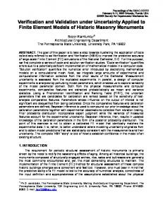
derived from the system model by a semantic-preserving transformation. If under this assumption a tested property is not fulfilled by the implementation then it must be due to faults in the model. As a consequence, we have lifted up both verification and validation from the implementation layer to the model layer. For verification of properties, first a suitable formal verification tool (e.g. a model checker) has to be chosen capable of verifying the aspects associated to the property. For example, for the property of deadlock freedom, the model checker has to support the aspects of concurrency, communication and interaction of processes. After identification of such a verification tool, conditions need to be established for the property. These conditions are specified within the specification language understood by the verification tool. Note that, different from a property, a condition is bound to a concrete specification language and it can well be the case that the same property is expressed differently in different specification languages. As model checkers typically operate on formal specification languages and we focus on a UML-based development process, for verification of conditions, a UML model must first be translated into such a specification language. Rather then designing a complete translation of the UML model it is advisable to restrict the translation to those aspects that contribute to the conditions. This is due to the well-known limitations of model-checking and because of the difficulty of defining a complete formal semantics of the UML model in terms of the formal language understood by the model checker. For example, when verifying a property that has to do with communication and interaction of components such as deadlock freedom, submodels of the UML model that have to do with the structure aspect such as class diagrams need not be formalized. For designing such a partial translation, we have shown that a graph transformation approach is well-suited [14]. In Figure 1, the different steps within model-based verification are illustrated. Given a UML system model, this is transformed into a formal specification applying pre-defined graph transformation rules. Additionally, the properties are manually encoded into formal conditions. Then both the formal conditions and the formal specification are analyzed with a formal verification tool to prove the formal conditions. The results are visualized within a result 5
Engels et al.
model, typically using the same visual modeling language as in the system model. This result model can be used by the developer to improve the system model according to the verification results. For validation of properties, tests check conformance of the system under test to a specification by simulating the model or testing an implementation derived from the model. Tests must be designed as a sufficient representative of the checked property of the system under test. As a consequence, software testing relies on the execution of code using different test inputs for one property. For testing such a specific property, a test case specifies the pre-test state of the implementation under test, the test inputs and the expected results. A test suite is a collection of test cases, typically related by a common goal [4]. Following our discussion, one needs to answer the following questions concerning model-based validation: •
How to derive a test case or a test suite from UML models for the validation of a specific property?
•
How to execute a test case or a test suite to validate a specific property?
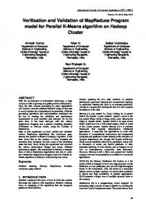
For deriving a test case from a UML model, an algorithm or heuristic is needed which we refer to as test strategy. The system model describes the implementation under test. A test model is a part of the system model, annotated with the properties to be tested. For example, for testing timing constraints, time expressions are attached on message or stimuli names of a sequence diagram of the system model. Such a sequence diagram is then used as a test model. Depending on the test strategy, test cases are derived from test models complemented by system models. We assume that test strategies define how test cases are derived from UML models such as sequence diagrams or class diagrams; this means a test strategy describes how to derive precise specifications of possible test cases from UML diagrams. For the execution of a test case, code of the system model is generated using graph transformation rules and the test cases are applied to the code under test. For example, for ensuring timing constraints of a system, a test strategy can define how test models derived from system models consisting of a set of sequence diagrams together with timing constraints attached to each sequence diagram are used to create a test case. After applying code generation techniques to the system model, a test case or a test suite is used to validate the resource constraints. In Figure 2, the different steps within model-based validation are illustrated. Given a UML system model, this is transformed into a part of the implementation in a programming language applying pre-defined graph transformation rules. Additionally, the test model or the UML system model is transformed into a test case or a test suite. Then the implementation of the system is executed with the test case as input. The test results are visualized with a result model using the same visual 6
Engels et al. UML System Model
Test Suite
graph transformation
generation according to test strategy
Result Model
visualization
Test Model
Implementation
Test execution
Test results
Fig. 2. Steps within model-based validation of properties
modeling language as in the system model. This result model can be used by the developer to improve the system model according to the test results. By applying these techniques of model-based verification and model-based validation of properties, important properties can be either verified or validated within model-based development. For model-based verification of properties, a partial translation of the UML model into the formal language of a model checker must be pre-defined. For model-based validation of properties, a suitable test strategy must be pre-defined, which defines how to derive test cases from system models and how to apply them. In the remainder of the paper, we will now illustrate both model-based verification and validation with an example.
4
Verification of Deadlock Freedom
In this section, we will concentrate on the verification of a specific property, deadlock freedom. In general, deadlock freedom is the property that a collection of components working together cannot reach a deadlock state. Such a deadlock state can be characterized by the situation that no component can make any progress. Within our system model, we will be interested in deadlock freedom of a collection of objects working together. We will assume a low-level system model consisting of a class diagram and additionally collaboration diagrams. In order to support the modeling of concurrent systems, we will assume that this low-level system model is expressed in UML-RT [22], a profile of UML for modeling real-time systems and incorporating the concept of components called capsules. In the following, we shortly describe concepts of UML-RT. Then we will concentrate on the verification of deadlock freedom within such a low-level system model. 4.1
UML-RT
Concerning the modeling language, we will use UML-RT [22], a profile of UML for modeling real-time systems and incorporating the concept of components called capsules. In the following, we shortly describe concepts of UML-RT and 7
Engels et al. Protocol RoleA
RoleB SProtocol
SA
SB
CapsuleA:
P2:Protocol::RoleB
P1:Protocol::RoleA
CapsuleB:
Fig. 3. Submodels and their usage in UML-RT
then we relate submodels used within UML-RT to the previously identified aspects. UML-RT is an extension of the UML by introducing the notions of capsules, ports, connectors, protocols and protocol roles. Originally targeted at enabling modeling of complex real-time systems, UML-RT has also been seen as a 1 candidate for modeling software architectures [21] and for modeling concurrent systems in general. In the following, concepts of UML-RT are explained in detail. A capsule is a stereotyped active class and is used for modeling a self contained component of a system. Other than ordinary classes, capsule operations can only be called from within the capsule. For communication with other capsules a capsule may have one or more ports through which it is interconnected to other capsules via connectors. A connector is an association between capsules. It represents a hardware connection via which capsules communicate by sending and receiving signals. These signals enter or leave a capsule at a port. A port realizes a protocol role which specifies the signals sent and received via the port. One or more protocol roles form a protocol. From the point of view of behavioral modeling, a statechart may be associated to a capsule. A capsule statechart describes how the capsule reacts to signals received via its ports and when signals are sent via its ports. State transitions of capsule statecharts may also include calls of capsule operations. For protocols, there exist also the possibility of modeling all valid sequences of message exchanges in a protocol statechart. The protocol statechart therefore expresses requirements rather than specifying the implementation of a protocol. In Figure 3, concepts of UML-RT are illustrated using a very simple example consisting of two capsule instances CapsuleA and CapsuleB connected by a connector via the two ports P1 and P2. The ports are bound to the protocol roles RoleA and RoleB, respectively. Each capsule is associated to a capsule statechart, SA and SB respectively, describing the dynamic behavior of the capsule. The protocol statechart SProtocol is associated to the connector 8
Engels et al.
between the two capsules. After introducing UML-RT as the language for specifying the system model and fixing the property deadlock freedom to be verified, in accordance with Figure 1 we have to •
choose a suitable formal language and a model checker
•
define a partial mapping of a UML-RT model into the language of the model checker
•
define conditions for deadlock freedom in the language of the model checker
4.2
The formal language CSP and the model checker FDR
We choose as a formal language CSP [17] which provides a mathematical model for concurrency based on a simple programming notation and supported by tools [12]. Next, we briefly review the syntax and semantics of the CSP processes we are using. Given a set A of actions and a set of process names N , the syntax of CSP is given by P ::= STOP | SKIP | a → P | P [A | B ]P | P u P | P 2P | P \ a | pn where a ∈ A, A, B ⊆ A, and pn ∈ N . Process names are used for defining recursive processes using equations pn = P . The interpretation of the operations is as follows. The processes STOP and SKIP represent, respectively, deadlock and successful termination. The prefix process a → P performs action a and continues like P . The parallel composition P [A | B ]Q results in an interleaving of P and Q except for the actions in A ∩ B , which have to be performed synchronously. The processes P u Q and P 2 Q represent internal and external choice between P and Q, respectively. That means, while P u Q performs an internal (τ -)action when evolving into P or into Q, for P 2 Q this requires an observable action of either P or Q. For example, (a → P ) u (b → Q) performs τ in order to become either a → P or b → Q. Instead, (a → P ) 2 (b → Q) must perform a or b and evolves into P or Q, respectively. This distinction shall be relevant for the translation of statechart diagrams below. Finally, the process P \ a behaves like P except that all occurrences of action a are hidden. The semantics of CSP is usually defined in terms of traces, failures, and divergences [17]. A trace is just a finite sequence s ∈ A∗ of actions which may be observed when a process is executing. A failure (s, A) provides, in addition, the set A of actions that will be refused by the process after executing s. Divergences are traces that are followed by infinite internal computations (without any communication). We denote by T (P ) the set of all traces of P. Together with these semantic models come several notions of process refinement. We write P vT Q if T (Q) ⊆ T (P ), i.e., every trace of Q is also 9
Engels et al.
a trace of P . Analogously, P vF Q if the failures of Q are included in the failures of P , etc. In general, the idea is that Q is a refinement of P if Q is more deterministic (more completely specified) than P . These refinement relations shall be used to express consistency constraints. 4.3
A partial mapping of UML-RT to CSP
For the property of deadlock freedom, we can restrict our mapping of a UMLRT model to statecharts associated to capsules. Our concept of mapping of statecharts to CSP processes relies on graph transformation rules and is inspired by Hiemer [15]. For a precise description of our mapping, the reader is referred to [10] and [8], detailing the use of graph transformation techniques. In the following, we briefly summarize our results: For each capsule statechart S, a CSP process is constructed (denoted by CSP (S )) parameterized over the states of the statechart. Similarly, we also translate the protocol statechart into a CSP process. Additionally, we define for each CSP process CSP (S ) a view process that restricts the process to the messages exchanged via a specific port p and denote this process by Vp (CSP (S )). Informally, this view process mirrors our decision to concentrate on messages sent over a specific port. According to the UML specification, each statechart is associated to an event queue where incoming messages are stored. However, the behavior of such an event queue is not defined. In order to be both precise and flexible about the size of buffers and their behavior, we assume that the storage and scheduling of events is the task of the connectors. Currently, connector behavior is not supported by UML-RT. For this reason, we propose to use connector stereotypes for selecting specific, pre-defined connector behavior. We associate every connector stereotype to a CSP process CON describing its behavior. Given two capsules connected by two ports p1 and p2 via a connector associated to a connector process CON and capsule statecharts associated to the capsules named SA and SB , we define the semantics of this construct by Vp1 (CSP (SA )) |[ p1in , p1out ]| CON |[ p2in , p2out ]| Vp2 (CSP (SB )) We denote this process with CSPp1 ,p2 (SA , CON , SB ). 4.4
Conditions for Deadlock Freedom and Verification
Having described the partial mapping of UML-RT models into CSP, we are now able to specify conditions for models translated to CSP: Condition 1 (Deadlock freeness) Two capsule statecharts SA and SB of two capsules connected by a connector with behavior CON via the ports p1 and p2 are deadlock free, if the induced system of CSP processes 10
Engels et al.
Fig. 4. The FDR tool and a trace to a deadlock
CSPp1 ,p2 (SA , CON , SB ) is deadlock free. Given a concrete UML-RT model, this can be translated into CSP using the partial translation described above. Then, the model checker FDR is used for evaluating the condition of deadlock freeness. The output of the model checker will then be either that the model is deadlock free or it will output a counterexample (see Figure 4).
5
Validation of Properties
In this section, we will illustrate the validation of a specific property, timing constraints. In general, for the conformance to timing constraints it must be assured at runtime that the system performs certain computations within a pre-defined time span. A general problem regarding model-based validation is that the usage of UML models varies from one development method to another. If there are no specific assumptions about the usage of UML models (like in [2]), it is difficult to automate the testing approach. To allow the automatic derivation of test cases from UML system models, we assume the model-based development presented in section 2. In the following, we shortly describe how to derive a test model from a system model. Then we will concentrate on a specific test strategy for deriving test cases from a UML model for the validation of timing constraints. 11
Engels et al. : TransactionControl
b : Bill
accA : Account
accB : Account
a:payBill(b) {a.executionTime = amount]
[this.balance