Dushman (26) derived an expression which is an approximation of the so-called Clausing's fac- tor (K'). This approximation is accurate within 10% com- pared to ...
1728
J. Electrochem. Soc., Vol. 138, No. 6, June 1991 9 The Electrochemical Society, Inc.
3. (a) A. Kuramata, S. Yamazaki, and K. Nakajima, Extended Abstracts of "22nd Conf. on Solid State Devices and Materials," Jpn. Soc. Appl. Phys., Aug. 22, 1990; (b) R. R. Saxena, J.E. Fouquet, V.M. Sardi, and R. L. Moon, Appl. Phys. Lett., 53, 304 (1988).
7.
4. P. Daniel, H. D. Sarge, and W. Weiner, "Proc. VII Intl. Conf. on Ion I m p l a n t a t i o n Technology," July 30, 1990, Surrey, England.
8.
5. (a) D. Kotecki, J. Blouse, C. Parks, and S. Sarkozy, "Proc. MRS S y m p o s i u m on Chemical Perspectives in Microelectronics," Nov. 26, 1990, Boston, MA; (b) T. E. Tang, in "Technical Digest International Electron Device Conference," IEEE, New York (1989). 6. (a) D. S. Williams and E. A. Dein, This Journal, 134, 657
10.
9.
11. 12.
(1987); (b) W. Kern and R. C. Helm, ibid., 117, 562 (1970). C. L. Keller and P. L. Tucker, "Hazardous Materials Regulations of the Department of Transportation," U.S. Bureau of Explosives, Washington, DC (1987). N. M. Gralenski, Microelectron., Manufact. Test., 10, 2 (1987). W. Kern, W. A. Kurylo, and C. J. Tino, RCA Rev., 46, 117 (1985). M. Shibata, T. Yoshimi, and K. Sugawara, This Journal, 122, 157 (1975). S. M. Sze, "VLSI Technology," McGraw-Hill, Inc., New York (1983). W. Kern, G. L. Schnable, and A. W. Fischer, RCA Rev., 37, 3 (1976).
Modeling and Optimization of the Step Coverage of Tungsten LPCVD in Trenches and Contact Holes A. Hasper, J. Holleman, and J. Middelhoek 1 Facutty of Electrical Engineering, University of Twente, 7500 AE Enschede, The Netherlands
C. R. Kleijn and C. J. Hoogendoorn Faculty of Applied Physics, Delft University of Technology, 2600 GA Delft, The Netherlands ABSTRACT A model is presented to calculate the step coverage of blanket tungsten low pressure chemical vapor deposition (W-LPCVD) from t u n g s t e n hexafluoride (WF6). The model can calculate tungsten growth in trenches and circular contact holes, in the case of the WF6 reduction by H2, Sill4, or both. The step coverage model predictions have been verified experimentally by scanning electron microscopy (SEM). We found that the predictions of the step coverage model for the Ha reduction of WF 8 are very accurate, if the partial pressures of the reactants at the inlet of the trench or contact hole are known. To get these reactant inlet partial pressures, we used a reactor model which calculates the surface partial pressures of all the reactants. These calculated surface partial pressures are used as i n p u t for our step coverage model. I n this study we showed that thermodiffusion plays a very important role in the actual surface partial pressure. I n the case where Sill4 was present in the gas mixture trends are predicted very well but the absolute values predicted by the step coverage model are too high. The partial pressure of HF, which is a by-product of the Ha reduction reaction, may be very high inside trenches or contact holes, especially just before closing of the trench or contact hole. We found no influence of the calculated HF partial pressure on the step coverage. Differences between step coverage in trenches and contact holes, as predicted by the step coverage model, were found to agree with the experiments. It is shown that the combination of the step coverage and reactor model is very useful in the optimization towards high step coverage, high throughput, and low WF6 flow. We found a perfect step coverage (no void formation) in a 2 ~m wide and 10 i~m deep (2 x 10 i~m) trench using an average WF6 flow of only 35 sccm, at a growth rate of 150 nm/min. I n general, it is shown that the reduction ofWF 6 by SiH~ offers no advantages over the reduction by H2 as far as step coverage is concerned. With the increasing degree of complexity in integrated circuits the aspect ratio of contacts and vias also increases. These geometries require deposition techniques capable of filling s u b m i c r o n high aspect ratio contact holes without void formation. Blanket tungsten, deposited by LPCVD and s u b s e q u e n t back etching (Fig. la), is widely used to fill these contacts (1, 2). A second possibility is to fill these contacts using a selective deposition scheme (3-11), in order to avoid the need of back etching (see Fig. lb). A n advantage of selective over blanket deposition of t u n g s t e n is the economic use of WF6. However, selective deposition of t u n g s t e n is only possible when all the contacts are equal in depth (12), which is not always the case (see Fig. 2). Other disadvantages of selective deposition of t u n g s t e n are the sensitivity to pretreatments and the nonreproducibility. To deposit t u n g s t e n two reducing agents are widely used. First the H2 reduction reaction of WF~ with the following overall reaction WF6 + 3H2 --->W + 6HF [1] Second, the Sill4 reduction reaction of WF6 2WF6 + 3Sill4 -> 2W + 3SiF4 + 6H2 [2] The H2 reduction reaction has shown its excellent step coverage (1, 2), b u t it has some disadvantages compared to the Sill4 reduction reaction such as low and very temperature d e p e n d e n t growth rate (3-5) and rough layers (1, 2, 13). 1Deceased.
The Sill4 reduction reaction however has a high and nearly temperature i n d e p e n d e n t growth rate and results in layers with a small grain size (1, 11, 13, 14). The reactivity of WF8 with silicon in the case of the Sill4 reduction reaction is m u c h less than the H2 reduction reaction. The WF6 reaction with silicon results in the undersirable gouging and encroachment of silicon. The problem of step coverage has been evaluated in the case of physical vapor deposition (PVD) (24). In that case, .
.
.
.
.
.
.
.
.
.
.
.
.
"
.
,
.
.
.
.
-
Oxide
Silicon la
W-LIDCVD Oxide Silicon lb
Fig. 1. (a) Blanket deposition of tungsten and subsequent back-etching and (b} selective deposition of tungsten.
Downloaded 23 Jun 2009 to 130.89.112.86. Redistribution subject to ECS license or copyright; see http://www.ecsdl.org/terms_use.jsp
J. Electrochem. Soc., Vol. 138, No. 6, June 1991 9 The Electrochemical Society, Inc. C
Blanket tungsten
ism for mass transfer. Because the Knudsen diffusion rate is m u c h smaller than bulk diffusion, concentration gradients can occur easily during the growth. The reactants m o v e into the feature by random flights interrupted by collisions and m o m e n t a r y adsorption on the wall9 The gas flow is delayed by the wall resistance. This is the so-called Knudsen flow. According to the kinetic theory of gases (25, 26), the K n u d sen diffusion coefficient can be written as follows. For a contact hole with radius r
M=First metal level Active
Fig. 2, Differences narization.
1729
Area
in contact depths that may be present after
2 r.(8RTtIJ2 = 5"
pla-
[3a]
And for a trench with a width w the step coverage is dominated by geometrical sidewall shadowing and surface diffusion. This approach is not applicable for CVD processes 9 McConica et al. (15) were the first to propose that W-LPCVD in circular contact holes could be described by the simultaneous heterogeneous reaction on the side wall and diffusion along the contact hole. Our step coverage m o d e l is also based on these assumptions. In this report we extend the model of McConica et al. to a numerical W-LPCVD model for zero- and first-order reactions allowing other geometries (like trenches) and accounting for tungsten growth on the bottom of the ge'ometry in the model boundary conditions. The step coverage of W-LPCVD has been investigated experimentally as well as theoretically (1, 2, 15-23). However, using the combination of the output of a reactor model as input for a step coverage model for the reduction of WF6 by H2 and/or Sill4 has not been reported yet. For the H2 reduction reaction an analytical solution of the step coverage can be found in terms of deposition parameters ignoring tungsten growth at the bottom of the features (15). For the Sill4 reduction reaction no such analytical solution can be obtained and numerical methods are necessary. Theory
In our study we defined the step coverage as the ratio in percents of the tungsten thickness (a) taken halfway the feature depth and the substrate surface thickness (b) at the m o m e n t the feature closes. This definition is shown in Fig. 3. Thus we obtain 100% step coverage if no void formation occurs. the pressures (100 Pa) and temperatures (673 K) c o m m o n in W-LPCVD, the mean-free path for the reactants is about 100 ~m. This is m u c h larger than the typical feature diameter. Whenever the mean-free path of the reactants is larger than the diameter of the feature (25, 26), K n u d s e n diffusion is the dominating mechanKnudsen
diffusion.--At
12
_
l
_
Dk = Dk = " K' -- - " r" '
3
\~-M/
-
i
)
1 + 8 -. r/3- 1
[4a]
For trenches Dk = Dk,= " K' = - - w 3
\ ~M/
9
(
1
) [4b]
1 + 8 " w / 3 91
During the growth, the dimensions of the feature are changing, thus making these diffusion coefficients become time dependent. For the calculation of the step coverage we will use the following two equations. For contact holes 2 (8RT/U2.( 1 ) Dk [r(t), l(t)] = ~ . r(t) . \ ~rM / ![ + 8" r(t)/3 . l(t)
[5a]
( 8 R T ~ '/2
"t
6
4
> O -2
0
2
4
1
1 + 8 " w(t)/3 - l(t)
)
[5b]
S o m e remarks have to be made concerning these diffusion coefficients. First, these formulas are derived for tubes without bottoms 9 In reality molecules c a n b o u n c e back, but for high aspect ratio features, as studied in this paper, the influence of the bottom will be small. Second, the formulas are derived for features, which are regarded as being constant in cross section across the length. For high aspect ratio trenches and contact holes this is approximately the case during growth.
--.) a
-4
F r o m Eq. [3a] and [3b] the diffusivities of the reactants in infinitely long circular or rectangular tubes are known, however, in practice the aspect ratio is not infinite and the influence of the open end of the feature has to be considered. We have a molecular flow through an open end and a short tube. The tube conductance has to be corrected with a factor depending on the finite length and the influence of the diameter of the feature. This is investigated by Clausing (27), who found a rather complicated expression for this phenomenon. D u s h m a n (26) derived an expression which is an approximation of the so-called Clausing's factor (K'). This approximation is accurate within 10% compared to the Clausing's factor. The Knudsen diffusion coefficient corrected with this factor for circular contact holes is
2
/~m
-6
[3b]
Dk [w(t), l(t)] = 3 " w ( t ) . \ ~ - ~ ]
T
8
(8R.Tt lj2
For trenches
__i b
10
2
Dk~ =--'W.
6
Fig. 3. Schematic sketch of o cross section of a trench or a contact hale. Our definition of the step coverage (S.C.) S. C. = a / b * 100%.
The hydrogen reduction reaction.--During typical W-LPCVD conditions, the tungsten deposition rate from H2 and WF6, appears to be fully determined by surface chemistry. The overall reaction is given by reaction [1] and the growth rate is given by
Downloaded 23 Jun 2009 to 130.89.112.86. Redistribution subject to ECS license or copyright; see http://www.ecsdl.org/terms_use.jsp
J. Electrochern. Soc., Vol. 138, No. 6, June 1991 9 The Electrochemical Society, Inc.
1730
Fluxin
RH = Cl " [p(WF6)] ~ [p(H2)] 1/2" e x p (-EA/RT) for p(WF6) > 0 R~ = 0
for p(WF6) = 0
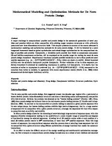
The silane reduction reaction.--WF6 c a n also b e r e d u c e d b y Sill4 (6-10) a n d o t h e r h i g h e r o r d e r s i l a n e s (8). T h e react i o n w i t h Sill4 t a k e s p l a c e a c c o r d i n g to r e a c t i o n [2] (31). I n t h e l i t e r a t u r e o n l y a f e w p u b l i c a t i o n s d e a l w i t h t h e Sill4 red u c t i o n r e a c t i o n o f WF6. R e f e r e n c e s (11, 14) as well as o u r o w n o b s e r v a t i o n s (see Fig. 4) i n d i c a t e t h a t t h e g r o w t h r a t e is first o r d e r i n t h e p a r t i a l p r e s s u r e o f Sill4, a n d n e a r l y ind e p e n d e n t o f t h e t e m p e r a t u r e i n t h e e x a m i n e d r e g i o n of 523 to 673 K. T h e d e p o s i t i o n r a t e is also zero o r d e r i n W F 6. T h e d e p o s i t i o n r a t e o f t h e Sill4 r e d u c t i o n r e a c t i o n c a n b e w r i t t e n as R~ = c2- [p(WF6)] ~ [p(SiH4)] 1 for p(WF6) > 0
[7a]
for p(WF6) = 0
[7b]
I n Eq. [7] C2 = 1.0 x 10 -8 m o l 9 c m -2 - s 1 - P a - L I n o u r m o d e l i n g s t u d y Eq. [6] a n d [7] a r e u s e d to c a l c u l a t e t h e g r o w t h rate.
M a t h e m a t i c a l model of deposition in trenches and contact holes.--The m o d e l is b a s e d o n a o n e - d i m e n s i o n a l m a s s b a l a n c e i n a c o n t a c t h o l e or t r e n c h . F o r t h i s m o d e l t h e foll o w i n g a s s u m p t i o n s h a v e to b e m a d e ; (i) t h e r e a c t i o n o n l y t a k e s p l a c e o n t h e w a l l a n d b o t t o m , (ii) t h e r e is n o s u r f a c e d i f f u s i o n , (iii) t h e l a t e r a l c o n c e n t r a t i o n g r a d i e n t s are negligible. W i t h t h e s e a s s u m p t i o n s t h e c o n c e n t r a t i o n profile i n t h e t r e n c h or c o n t a c t h o l e c a n b e c a l c u l a t e d . C o n s i d e r a s c h e m a t i c d i a g r a m of a v o l u m e e l e m e n t V of a t r e n c h as r e p r e s e n t e d i n Fig. 5 o(C~ 9 V) _ ( F l u x ~ 9A)
Ot
~L_. . . . . . . . . .
(Fluxou t 9 A)
-
R(C.
T).
n-
AA
[8]
x=x2
200 180
L
F l u x out Fig. 5. A schematic drawing of a differential element in a trench.
H e r e R(Ci, T) is t h e m o l a r r a t e of WF6 d i s a p p e a r a n c e p e r u n i t s u r f a c e a r e a as a f u n c t i o n o f t h e local m o l a r c o n c e n t r a t i o n Ci a n d t h e a b s o l u t e t e m p e r a t u r e T, ~ is a s t o i c h i o m e t r y c o n s t a n t d e p e n d i n g o n t h e c h e m i s t r y . AA is t h e a c t i v e surface o f t h e v o l u m e e l e m e n t V o v e r w h i c h t h e r e a c t i o n t a k e s place. A is t h e c r o s s - s e c t i o n a l a r e a o f t h e t r e n c h or c o n t a c t hole. I n o u r s t e p c o v e r a g e s t u d y w e c o n s i d e r e d t w o geometries I. A r e c t a n g u l a r t r e n c h w i t h initial w i d t h W0 a n d initial d e p t h L0. II. A c i r c u l a r c o n t a c t h o l e w i t h initial r a d i u s R0 a n d initial d e p t h L0. F o r t h e s e t w o g e o m e t r i e s t h i s r e s u l t s i n t h e f o l l o w i n g diff e r e n t i a l e q u a t i o n s for t h e m o l a r c o n c e n t r a t i o n s C~ as g i v e n b y t h e following. For trenches
O(Ci . w) -
-
Ot
o { -
T ) 9 "q
[9a]
OxO { r2 " Dk " OCilj - 2 " R(Ci' T) " ~ "
[9b]
9 Dk 9
Ox )
-
2 9 R(Ci,
For contact holes
W h e r e t h e v a r i a b l e s C~, w, r, a n d Dk are f u n c t i o n s o f t h e pos i t i o n a n d t i m e . N o w f r o m Eq. [9a] a n d [9b] a n d a c c o r d i n g to r e a c t i o n [1] o r / a n d [2] w e c a n w r i t e a set of d i f f e r e n t i a l e q u a t i o n s for t h e WF6, Sill4, Ha, SiF4, a n d H F c o n c e n t r a tion. F o r e x a m p l e t h e d i f f e r e n t i a l e q u a t i o n of t h e WF6 concentration in a trench becomes
o w(x, t) . D~ . Ox -~x J - 2 9 {RH(CH, Cw, T) + Rs(Cs, Cw)} [10]
120 T h e c h a n g i n g d i a m e t e r s o f t h e f e a t u r e s are g i v e n b y t h e following differential equations For trenches
100 rr
OC~ w
Ox
140 E
X 2
V
O{Cw . w(x, t)} Ot
160
X 1
-
O(C~ "
x=:~1 --
o
[6b]
R e c e n t l y , it w a s f o u n d t h a t t h e d e p o s i t i o n r a t e is i n d e e d z e r o - o r d e r d o w n to v e r y l o w p r e s s u r e s o f WF6 (28, 38). I n t h e l i t e r a t u r e (3-5, 28-30) EA is f o u n d to b e 67-73 k J / m o l . B a s e d o n t h e e x t e n s i v e e x p e r i m e n t a l set p u b l i s h e d b y B r o a d b e n t a n d R a m i l l e r (3), E A is t a k e n at 69 k J / m o l a n d c] = 1.7 x 10 .4 tool - P a -u2 - c m -2 - s -1. T h e s e v a l u e s w e r e s h o w n to b e i n g o o d a g r e e m e n t w i t h o u r o w n e x p e r i m e n t s . B e c a u s e EA a n d c~ w e r e d e r i v e d f r o m e x p e r i m e n t s i n a h o t wall system, the values are not suffering from uncertainties i n t h e w a f e r t e m p e r a t u r e .
R~ = 0
W
[6a]
8O 6O
Ow(x, t) Ot
4O 20
2
{Rs(Cw, Cs) + R~(Cw, CH, T)}
[lla]
Pw
For contact holes
0 0
i
i
i
1
2
3
p(SiH4,wafer)
4
[Pa]
Fig. 4. Growth rate as a function of the partial pressure of Sill4 (Tw~ = 6 7 3 K, P,ot = 133 Pa, Ar = 1.5 slm, and WF6 = 150 sccm).
Or(x, t)
{Rs(Cw, Cs) + RH(Cw, CH, T)}
Ot
Pw
[llb]
B y s o l v i n g t h e p a r t i a l d i f f e r e n t i a l e q u a t i o n s for all react a n t s , t h e c o n c e n t r a t i o n of WF6, Sill4, H2, SiF4, a n d H F c a n be determined. From these concentrations the growth rate
Downloaded 23 Jun 2009 to 130.89.112.86. Redistribution subject to ECS license or copyright; see http://www.ecsdl.org/terms_use.jsp
J. Electrochem. Soc., Vol. 138, No. 6, June 1991 9 The Etectrochernical Society, Inc. at any point in the trench or in the contact hole can be calculated and thus the deposition profile and the step coverage (see Fig. 3). Suppose that the reactor is operating under steady-state conditions, the concentrations of the reactants at the mout h of the feature are constant. The initial conditions for the partial differential equations, for all x, are
(contact holes)
3"-WAF~:~ 8"--WAFE~ SL,IS(::EPTOI:~
[12c]
l(0)
[12d]
= L0
The boundary conditions for the concentration C~, for all t, are x = 0 Q(0, t) = C.0
At
[12b]
w ( x , O) = Wo (trenches)
x . Lo. D~ . . OCi . 3x
(:~.JARTZ W I N D O ~
[12a]
Ci(x, O) = Ci.o r(x, O) = Ro
173t
[13a]
~ - {Rs(Cw, Cs, T) + Rs(Cw, Cs)} [13b]
The partial differential Eq. [9] and [11] have to be solved numerically with the initial conditions of Eq. [12] and the boundary conditions of Eq. [13]. The boundary conditions at the bottom of the feature are based on the assumption that at the end of the feature the diffusive flux towards the bottom is equal to the c o n s u m p ti o n of the reactant by the chemical reactions. The partial differential equations were solved numerically using a fully implicit scheme (32). This implicit scheme is stable even for large time steps. The discretization m e t h o d we used has a first-order accuracy in time and a second-order accuracy in space. For most of the calculations the total trench depth was divided into 20 equidistant pieces. The grid independence was checked for a representative situation using 50 and 100 grid points. The calculated step coverage obtained on these fine grids differed less than 0.5% from those obtained on a standard grid of 20 grid points. The time step was chosen to satisfy t h e re qu i r em en t that the concentration change between two time steps did not differ more than 0.1% from the previous calculation. The m a x i m u m time step was set to 5 s. We solved the differential equations with full-time dependency. This d e v e l o p m e n t differs from (22, 23) where these equations were solved using steady- or pseudo steady-state approximations. McConica et at. recently (17) concluded that the steady- or pseudo steady-state solution is only valid for conditions of no significant depletion of the reactants. In the case of conformal deposition and high aspect ratio features the length of the feature does not change much. In this regard, one should note that for nonconformal feature fillings, the length of the feature is increasing during deposition. In our model we also account for this changing length of the feature during deposition.
Experimental Procedure The step coverage experiments of tungsten LPCVD were performed in an ASM cold wall single-wafer reactor, which is designed for handling 8 in. wafers. In our experiments an 8 in. wafer is used as carrier for a 3 in. p-type 10 ~ - cm (100) wafer. In all the experiments the deposition area was over the whole 8 in. wafer. A schematic sketch of the reactor and the gas lines is presented in Fig. 6. The walls of the reactor c h a m b e r are water cooled. The wafer is placed on a graphite susceptor, which is placed on a quartz dome. The susceptor is heated indirectly by a heating element. Gases are injected radially near the top of the reactor perpendicular into a 0.20 m diam gas tube. This tube is positioned perpendicular to the wafer surface. The purity of the gas sources (WF6, Sill4, H2, Ar) employed for the experiments was 99.999%. In cold wall LP C V D reactors the temperature of the wafer is not equal to the temperature of the susceptor, but is related to total pressure, gas composition, coating of the wafer, and the temperature of the susceptor. The temperature of the susceptor could be measured by a series of ther-
TO pIMp
H2
Sill4
WF6
TO PLIvlP
Fig. 6. Schematic sketch of the cold wall reactor and the gas lines. mocouples. By knowing the temperature of the susceptor, the gas composition, and the total pressure the wafer temperature could be determined from calibration tables with an accuracy of -+5 K. The calibration was done by measuring the temperature o f a Si wafer (p+-0.02 D 9cm) as a function of the susceptor temperature, the gas composition, and the total pressure. The temperature of the Si wafer (p+-0.02 D - cm) was measured with the use of a dual wavelength pyrometer (2.1 and 2.3 ~m). Trenches and circular holes were reactive ion etched (RIE) using a gas m i x t u r e of Clz and SIC14. The trenches and circular holes were etched with SiO2 as a mask to a depth of about 10 ~m and have a diameter ranging from 1 to 4 ~m. After RIE etching the SiO~ was r em o v ed in HF (1:6). J u s t before tungsten deposition the wafers received a dip of 30 s in 1% HF. Each tungsten deposition was preceded by an i n s i t u deposition of a silicon reduced tungsten film (10 sccm WF~, 1.5 slm Ar, PTOT = 133 Pa, TWAFER = 673 K) of 25 -+ 5 n m (13). The thickness of the tungsten films and the step coverage was determined by SEM observations. The use of trenches instead of contact holes as a test vehicle for step coverage is very applicable, because cleaves through trenches can be obtained easily and the trench cleaves expose the real deposition profile. Getting straight cleaves through the middle of contact holes of micron dimensions is hardly possible. Cleaves of contact holes that do not go through the middle, reflect a wrong step coverage. This advantage of trenches as a test vehicle for monitoring step coverage has been described earlier by Schmitz et al. (1). The step coverage as calculated by the step coverage model were compared with SEM observations. Absolute step coverages as determined by SEM observations have an overall accuracy of -+5%. The experiments on step coverage used in this study and the deposition parameters are s u m m e d up in A p p e n d i x A.
Results M o t i v a t i o n f o r u s i n g a reactor m o d e L - - I n order to get precise knowledge of the reactant partial pressures a reactor model is used. The distribution of the reactants are mainly determined by hydrodynan:dcs and transport phenomena. Especially in the case of cold wall single-wafer reactors where deposition rates are high and the walls are cooled, the inlet concentrations do not represent the reactant concentrations just above the wafer surface. These reactant wafer concentrations have to be known in order to calculate the step coverage. The reactor model is used to determine the partial pressures of the reactants just above the wafer surface. These partial pressures are used as input for our step coverage model. In the study (28, 38) of growth rates as function of the inlet flows of WF6, H2, and Ar, it became clear that the inlet concentrations in cold wall reactors do not represent the wafer surface concentrations. The conversion rate, which is often used as criterion for gradientless reactor operation, was shown to be not a good criterion, not even in the case of hig]b gas flows. This study also showed the importance of thermal diffusion phenomena. Due to this thermal diffusion, wafer surface partial pressures of WF6 will always be lower than the inlet partial pressure. Thermal diffusion causes the relatively heavy WF6 molecules to m o v e away from tile hot susceptor. From
Downloaded 23 Jun 2009 to 130.89.112.86. Redistribution subject to ECS license or copyright; see http://www.ecsdl.org/terms_use.jsp
J. Electrochem. Soc., Vol. 138, No. 6, June 1991 9 The Electrochemical Society, Inc.
1732
Table I. Comparison between different methods to calculate WF~ partial pressures at the wafer surface.
Exp. 1 10
Conversion of WF6
p(WF6)a (Pa)
p(WF6)b (Pa)
p(WF6)~" (Pa)
49% 13%
49 3.99
2.26 3.59
1.06 2.00
p(WF6)at wafer surface supposed equal to inlet partial pressure. b p(WF~) at wafer surface supposed equal to outlet partial pressure. c p(WF6) at wafer surface calculated by reactor model.
the above it is clear that a reactor m o d e l which incorporates thermal diffusion effects is necessary for determining the actual reactant concentrations at the wafer surface. Another advantage of the reactor model is the knowledge of reaction by-product partial pressures just above the wafer surface. In that manner, possible influences of byproducts on the step coverage can be studied. A detailed description of the reactor model that we used can be found in (28, 33, 38). As m en t i o n ed previously the inlet partial pressure of the reactants, especially WF6, has to be k n o w n for accurately predicting the step coverage 9 For our step coverage model we used inlet partial pressures which were calculated by the reactor model. Other methods, such as accounting for the conversion of the reactants (outlet partial pressure), as used by others (16, 19, 23) are not accurate, because they do not incorporate thermal diffusion phenomena. In Table I the partial surface pressures of WF6 have been calculated using three different methods. From Table I, we can conclude that the m e t h o d of calculation for the WF6 partial pressure at the wafer surface can result in large differences, even in the case of low conversion, as in experim e n t 10. The reactor m o d e l calculations of the WF 6 partial pressures are m u c h lower than the other calculation methods. Th e step coverage m o d e l using the wafer surface partial pressure as boundary condition for its calculations will also be influenced by the reactant surface partial pressure. It must be noted that the reactor model predictions of the WF6 pressure at the wafer surface are relatively sensitive to small errors in the thermal diffusion coefficients, which were obtained from kinetic gas theory. For example, a 25% increase of the thermal diffusion coefficient led to a decrease in the WF6 surface partial pressure from 1.06 to 0.88 Pa for e x p e r i m e n t 1 and from 2.00 to 1.76 Pa for experiment 10. The resulting changes in predicted step coverages for a 2 • 10 ~m trench are from 77 to 74% for experim e n t 1 and from 82 to 80% for e x p e r i m e n t 10, respectively.
Table II. Influence of HF on step coverage. In all the experiments the partial pressure of Hz is kept on 110 Pa.
p(WF6) p(HF) surface surface (Pa) (Pa)
Exp. 1 2 3 4
1.04 1.47 1.98 2.38
Trench (Fm)
12.30 5.92 2.59 1.20
2.0 x 2.6 x 3.2 x 2.4 x
Growth rate (nm/min)
Exp. Model Exp.
l0 10 10 10
73 80 92 89
77 86 92 91
Model
87.2 77.4 57.4 41.8
91.7
83.0 62.2 44.7
that the influence of H F by-product on step coverage is negligible in the e x a m i n e d regime. In all cases of modeling on the Ha reduction reaction we found that the primary cause of the drop in step coverage is depletion of WF6 in the trench. Although the reaction is zero order in WF6, the reaction rate still becomes zero when the partial pressure of WF~ becomes zero. This effect of WF6 depletion is shown in Fig. 7 and 8, where partial pressure profiles of the reactants are shown at several stages during growth, for two typical cases Figure 7 -WFs:H2 = 1:1 Figure 8
-WF6:H2 = 1:10
In these two cases the partial pressure of Ha at the trench inlet was 17 Pa, H F partial pressure was 1.7 Pa, wafer temperature 723 K, resulting in a surface growth rate of about 50 rim/rain. The trenches were 2 • 10 ~m. F r o m Fig. 7 and 8 we see that the primary cause of the drop in step coverage is WF6 depletion rather than H2 depletion, in spite of the three times higher flux of H2. In general this is because of (i) the higher diffusivity of H2 compared to WF6 (about 12 times), (ii) in almost all cases H2 is available in excess; and (iii) growth rate has only a square root dependence on the H2 partial pressure. Thus considering the H2 partial pressure constant [cf. McConica et al. (15)] during growth does not influence the predicted value of the step coverage much. 20
2O
I
I i
i=900 S ii= t O 0 0 s
9
18 I
iii=110Q s
[
iv=12OO S
"
i
..
.
15
i
"
~
iv
11
~~
5
14 I TOP
The hydrogen reduction reaction.--In our step coverage study we did not account for any influence of the by-products on growth rate. For reaction [1] it has been found (29, 34) that H F can supress the tungsten growth rate. Others found that H F did not have more than a dilution effect (35) on deposition rate. It is very difficult to incorporate such influences of by-products in the step coverage modeling because little data are available, and these data are not consistent. In our case using the reactor model we can calculate the partial pressure of H F just above the wafer. If H F had some influence, the growth rate predicted by the reactor m o d el based on Eq. [6] and the experimental results at different H F partial pressures should contradict. Also the step coverages should be influenced by the in situ generated HF. Especially inside the trenches or contact holes the by-product partial pressures can be very high during growth. The influence of H F is examined in four experiments, w he r e the H F partial pressure was varied from 1.2 to 12.3 Pa. These varying partial pressures were achieved by changing total flow while maintaining a constant partial pressure of H2. The H F and WF6 partial pressures were calculated by the reactor model. The results of these four experiments are presented in Table II. F r o m these experiments we see that the influence of H F on step coverage is within the experimental error. F r o m this we m a y conclude
Step coverage (%)
BOTTOM
,21/
.
0
2
.
.
.
4
"~ 6
8
10
2
4
micrometers
6
8
10
micrometers
(a)
(b)
12
20
I
15 8 10
I
I
6 Hi 4
5
0
/TOP 2
2~
~, B O T Q ~ 4
6
micrometers
(c)
8
10
0 -6
' -4
-2
0
,
,
2
4
6
(d)
Fig. 7. Time varying partial pressures profiles in 2 x 10 I~m trench for WF6:H2 = 1:1 (a-c). Partial pressure at the trench inlet were (a, b) Hz = WF6 = 17 Pa, (c) HF = 1.7 Pa, T w a f e r ~ 723 K, resulting in a bulk growth rate of 50 nm/min. The deposition profile is shown in (d) resulting in a step coverage of 96%.
Downloaded 23 Jun 2009 to 130.89.112.86. Redistribution subject to ECS license or copyright; see http://www.ecsdl.org/terms_use.jsp
J. Electrochem. Soc., Vol. 138, No. 6, J u n e 1991 9 The Electrochemical Society, Inc. 2.00 i
2~t IB
--
1(5
1733
i=100 s ii=200 s
[i/ --,
1.50
iii=300 s iv=350 S
i
C,,,
i=900 s
1.00
~
i
i
3
i
iv
i
ii
2
ii=1000 s
iii=1100 s
14
0.50
BO~
TOP 12
B~
0.00
0
2
4
6
8
10
iiJ
i
2
0
4
6
8
TOP
10
/
0
TOP 0 z~'/'TO'P 2
0
4
micrometers
micrometers
6
8
10
2
0
micrometers
'
'B~OOT~TOOMM' I.
4
6
8
10
microrr~ter8
(b)
(a)
(a)
(b)
12 20
L___
10 3 84
1o
8
15
iv
10
6
4 TOP
BOTTO~
/
2 2
4
6
8
4f
5
/~m>
TOP
10
0 -6
micrometers
~m
8
iiii i
6 1
I
i
-4
-2
2
BOTTOM /.Am>
0
4
2
4
6
8
ol
10
-6
micrometers
(e)
-4
-2
0
2
4
(d)
Fig. 8. WF6:H2 = 1:10. WF6 partial pressure at trench inlet is reduced to 1.7 Pa, other porameters as in Fig. 7. In (d) the deposition profile is shown, step coverage drops to 86%.
When the growth rate stops due to a lack of WF6, we can see a redistribution of the H2 partial pressure. This effect is shown in Fig. 7a (compare t = 1100 s and t = 1200 s). The partial pressure of H F can be very high deep inside the trench or contact hole, as is shown in Fig. 7c and 8c. The resulting m o d el ed deposition profiles for these two cases are shown in Fig. 7d and 8d. In Fig. 9 the step coverage of all H2 reduction reactions is plotted as a function of the so-called step coverage modulus (SCM), first proposed by McConica et al. (15). This dimensionless n u m b e r is given by L~ 9 R
SCM -
(c)
Fig. 10. Time varying partial pressure profiles in a 2 x 10 t~m trench. Trench inlet partial pressures were; H2 = 1.3 Pa, Sill4 = 2.7 Pa, and WFe = 13 Po. Twafer = 673 K, resulting growth rate 150 nm/min. (a) H2 partial pressure, (b) Sill4 partial pressure, (c) WF 6 partial pressure, and (d) deposition profile, resulting S.C. = 84%.
the WF6 depletion but also by a changing Sill4 partial pressure in the trench or contact hole. In Fig. 10 and 11 partial pressures and deposition profiles are shown for two cases. First, where step coverage is determined by Sill4 depletion 3s
2.00 i=100 s ii=200 s iii=300 s
1.75
n
[14]
Wo " Dk" Cw.o
(d)
2.75
ii
1.50
Figure 9 shows that the m o d e l predictions and the experimental values fit well. For simplicity in this figure the changing length during growth is not incorporated, bec a u s e o t h e r w i s e a s i m p l e S.C. as f u n c t i o n o f t h e S C M
could not be determined. This makes Fig. 9 only valid for high aspect ratio features. In our experiments, geometries meeting this r e q u i r e m e n t are used.
2.50
I
2~!5
1.25 / TOP
BOTTq~
TOP 2.00
1.00 0
2
4
6
8
0
10
2
micrometers
4
6
e
10
4
6
micrometers (b)
(a)
The s i l a n e r e d u c t i o n r e a c t i o n . - - I n the case of the Sill4 reduction of WF6 step coverage is not only determined by
BOTTOM
12 2.00 l 100
~
9
exp- 1
z~
exp-2
o
exp-3
+
exp-4
~ /
9
exp-7
~ e
9
exp-9
xz
e x p - - 10
9
exp- 1 1
[]
e x p - 12
10 1"50
8 80
~N.
Mode/ g C~ u)
) 60
\
40
20 . 0.001
.
. . 0.01
.
. . 0.1
.
. 1
10
Step C o v e r a g e Modulus ( - )
Fig. 9. Step coverage predictions (--) and experiments as a function of the step coverage modulus (SCM).
1,00
..
r/~,
6 4
0,50
2 0.00
0
2
4
6
micrometers (c)
8
10
o _6
_4
-2
2
(d)
Fig. 11. Parameters as in Fig. 10, except WF 6 partial pressure decreased to 1.3 Pa. (a) H2 partial pressure, (b) Sill4 partial pressure, (c) WF6 partial pressure, and (d} deposition profile, resulting S.C. = 71%.
Downloaded 23 Jun 2009 to 130.89.112.86. Redistribution subject to ECS license or copyright; see http://www.ecsdl.org/terms_use.jsp
1734
J. Electrochem. Soc., 100
Vol. 138,No. 6, June 1991 9 The ElectrochemicalSociety,Inc.
L = 1 0 ,urn D= 2 ~rn T=673 K
/
/
60 ~!i/"
--ID(SiH4)=I Pa
/
---
p(SIH4)=2 Pa
----
p(SiH4)=3 Pa
40
20 0.1
1
10
100
Partial pressure W F 6 (Pa)
Fig. 12. Step coverage predictions as a function of the partial pressure of WF6 for three different partial pressures of Sill4. (a) p(SiH4) = 1 Pa (--); (b) p(SiH4) = 2 Pa (----), and (c) p(SiH4) = 3 Pa ( - - ) .
(see Fig. 10) and, second, step c o v e r a g e is d e t e r m i n e d by W F 6 d e p l e t i o n (see Fig. 11). I n b o t h m o d e l i n g cases t h e g r o w t h rate is m a i n t a i n e d at a b o u t 150 n m / m i n , t e m p e r a ture is 673 K. A t t h e inlet of t h e feature the partial p r e s s u r e of H2 is k e p t at 1.3 P a and t h e Sill4 partial p r e s s u r e is 2.7 Pa. In Fig. 10 WF6 partial p r e s s u r e is 13 P a and in Fig. 11 WF~ partial p r e s s u r e is 1.3 Pa. I n Fig. 10 t h e step c o v e r a g e is d e t e r m i n e d by Sill4 d e p l e t i o n and in Fig. 11 by WF e depletion. We also see an a c c u m u l a t i o n of H z in t h e trench, b e c a u s e H2 is a b y - p r o d u c t of t h e Sill4 r e d u c t i o n reaction. In t h e case of Sill4 r e d u c t i o n reaction, w h i c h is first-order in Sill4, a d r o p in Sill4 partial p r e s s u r e directly results in a l o w e r local g r o w t h rate. I n t h a t case the step c o v e r a g e is i n d e p e n d e n t on Sill4 partial p r e s s u r e b u t only d e p e n d e n t on the g e o m e t r y of the feature. In Fig. 12 the step c o v e r a g e p r e d i c t i o n s as a f u n c t i o n of the partial pressure of WF6 at t h r e e d i f f e r e n t partial p r e s s u r e s of Sill4 are shown. F r o m this figure it can be seen that the m o d e l p r e dicts s t e p c o v e r a g e s i n d e p e n d e n t of partial p r e s s u r e of Sill4 p r o v i d e d that t h e partial p r e s s u r e of WF6 is sufficiently high. A t partial p r e s s u r e s of WF~ l o w e r t h a n a b o u t t h r e e t i m e s the partial p r e s s u r e of Sill4 the step c o v e r a g e drops. T h e r e a s o n for this is WF6 d e p l e t i o n rather t h a n Sill4 depletion. F i g u r e 12 also s h o w s that it is f u n d a m e n tally i m p o s s i b l e to o b t a i n a step c o v e r a g e of 100% in a 2 x 10 txm t r e n c h u s i n g t h e Sill4 r e d u c t i o n reaction. T h e p r e d i c t e d i n d e p e n d e n c y of t h e step c o v e r a g e on a c h a n g i n g S i l l 4 partial p r e s s u r e at sufficiently h i g h partial p r e s s u r e o f WF6 is verified e x p e r i m e n t a l l y . T h e results are s h o w n in T a b l e III. F r o m this table we see that the step c o v e r a g e as p r e d i c t e d b y t h e m o d e l is h i g h e r t h a n w h a t is s e e n e x p e r i m e n t a l l y . U n t i l n o w it is not clear w h y t h e s e p r e d i c t e d v a l u e s of t h e step c o v e r a g e are too high. This m a y be a t t r i b u t e d to t h e fact that v e r y little kinetic data are available for this Sill4 r e d u c t i o n r e a c t i o n and the influence of by-products. T h e influence of SiF4 on the g r o w t h rate, as was s h o w n by S c h m i t z et aI. in a single e x p e r i m e n t (19), will affect t h e step c o v e r a g e to a l o w e r value. B e c a u s e of t h e u n k n o w n n a t u r e a n d influence of t h e b y - p r o d u c t s this is n o t i n c o r p o r a t e d in t h e s i m u l a t i o n models. E x p e r i m e n t a l l y w e f o u n d no influence of the Sill4 partial p r e s s u r e on step c o v e r a g e at sufficiently high WF~ partial pressures. T h i s is in a g r e e m e n t w i t h t h e m o d e l p r e d i c t i o n s and is a c l u e that t h e g r o w t h rate of t h e Sill4 r e d u c t i o n reaction is i n d e e d first o r d e r in Sill4. T h e step c o v e r a g e m o d e l p r e d i c t s a d r o p in step c o v e r a g e w h e n the WF6 par-
Fig. 13. SEM cross sections for P(SiH4) = 1.5 Pa, T,o~,, = 673 K. (o, top)p(WF 6) = 10 Po and (b, bottom)p(WF~) = 2.4 Pa. Step coverage in (a) is 7 0 % and in (b) 5 0 % for the 2 • 10 ~m trench.
tial p r e s s u r e is r e d u c e d to a p o i n t w h e r e step c o v e r a g e is d e t e r m i n e d by a l a c k of WFs. This is illustrated in two S E M cross sections w h e r e t h e surface partial p r e s s u r e of Sill4 is k e p t c o n s t a n t at a b o u t 1.5 P a but the partial p r e s s u r e of WF6 is r e d u c e d f r o m 10 to 2.4 Pa. This r e s u l t e d in a d r o p of the step c o v e r a g e f r o m 70 to 50% for t h e 2 • 10 txm trench, see Fig. 13a and 13b. In t h e case of t h e Sill4 r e d u c t i o n reaction of WF 6 the m o d e l p r e d i c t s h a r d l y any influence of t h e t e m p e r a t u r e . This is verified in t h r e e e x p e r i m e n t s . T h e results of t h e s e e x p e r i m e n t s are s h o w n in Fig. 14. A l t h o u g h t h e p r e d i c t e d v a l u e s are too h i g h t h e t r e n d is the same. Comparison of step coverage in trenches and contact ho~es.--For o b t a i n i n g e x p e r i m e n t a l step c o v e r a g e data, t r e n c h e s are v e r y c o n v e n i e n t , b e c a u s e it is m u c h easier to get cleaves t h r o u g h t r e n c h e s t h a n t h r o u g h c o n t a c t holes, especially w h e n t h e y are in t h e range of a few microns. Ano t h e r a d v a n t a g e of t r e n c h e s is that t h e y s h o w the real deposition profile. I n Fig. 15 a c o m p a r i s o n is m a d e b e t w e e n step c o v e r a g e v a l u e s p r e d i c t e d in t r e n c h e s a n d c o n t a c t holes of t h e s a m e d i a m e t e r d e p t h ratio. This figure is valid (within a few percent) for the Sill4 as well as the H2 reduction reaction. In one case it was possible to b r e a k exactly t h r o u g h a 3.2 x 10 F m c o n t r a c t hole, g i v i n g a step c o v e r a g e of 48%. T h e t r e n c h of 3.2 x 10 ~ m on t h e s a m e wafer r e v e a l e d a step c o v e r a g e o f 76%. This is in v e r y g o o d a g r e e m e n t with Fig. 15 (see d a s h e d line). T h e s e cleaves are s h o w n in Fig. 16a and 16b.
Table III. Step coverage in 2.2 x 10 p~m trenches at different partial pressures of Sill4. In these experiments the wafer temperature was 773 K, total pressure 133 Pa. 1.4 slm argon was used as carrier gas.
Exp. 14 15 16
Conversion of WF6 (%)
p(WF~) surface (Pa)
p(SiH4) surface (Pa)
Growth rate (nm/min)
Step coverage experiment (%)
Step coverage model prediction (%)
2 4 6
10 10 10
0.50 1.00 1.50
30.1 56.4 87.5
70 70 70
84 84 84
Downloaded 23 Jun 2009 to 130.89.112.86. Redistribution subject to ECS license or copyright; see http://www.ecsdl.org/terms_use.jsp
J. Electrochem. Soc., Vol.
138, No. 6, June 1991 9 The Electrochemical Society, Inc.
1735
100
80
60
-
~ o d e /
-
Experiment~j~_~_
q
u)
4O p(WF6)=2.4 Pa 2O
p(SiH4)= 1.2 Pa
T r e n c h = 2 x 10 ~ m | i i i 0 4 5 0 500 550 6 0 0 650 700 7 5 0 Temperature (K) Fig. 14. Influence of temperature on step coverage.
Process optimization.--From t h e r e s u l t s of t h e simulat i o n s a n d t h e e x p e r i m e n t a l v e r i f i c a t i o n it is n o w p o s s i b l e to o p t i m i z e t h e s t e p c o v e r a g e . F o r t h i s o p t i m i z a t i o n s o m e r e q u i r e m e n t s c o n c e r n i n g t h e W - L P C V D p r o c e s s i n a single w a f e r r e a c t o r h a v e b e e n m a d e : (i) to get v o i d - f r e e filling of a h i g h a s p e c t r a t i o c o n t a c t , s t e p c o v e r a g e s h o u l d b e 95% i n a f e a t u r e w i t h a n a s p e c t ratio o f 5, (ii) for a t h r o u g h p u t o f 10 w a f e r s / h , t h e g r o w t h r a t e s h o u l d b e 150 n m / m i n , (iii) for e c o n o m i c r e a s o n s c o n v e r s i o n of WF6 s h o u l d b e h i g h a n d t o t a l W F 6 flow s h o u l d b e low. W i t h t h e u s e of t h e r e a c t o r m o d e l a n d t h e s t e p c o v e r a g e m o d e l t h e s e d e m a n d s c o u l d b e fulfilled. I f a s t e p c o v e r a g e o f 95% is req u i r e d i n a f e a t u r e w i t h a s p e c t ratio o f 5 t h e Sill4 r e d u c t i o n r e a c t i o n , as w e s a w b e f o r e (see Fig. 12), is n o t suitable. So w e h a v e to c h o o s e t h e Hz r e d u c t i o n r e a c t i o n . F r o m Eq. [6] w e s e e t h a t w e h a v e to i n c r e a s e t h e p a r t i a l p r e s s u r e o f H2 a n d t e m p e r a t u r e to o b t a i n a h i g h g r o w t h rate. W i t h r e g a r d to m u l t i l e v e l m e t a l l i z a t i o n t h e m a x i m u m t e m p e r a t u r e is l i m i t e d to 693 K, b u t if w e i n c r e a s e t h e g r o w t h r a t e b y i n c r e a s i n g t h e p(H2), s t e p c o v e r a g e d r o p s , see Eq. [14]. H o w e v e r , a n o t h e r w a y to i n c r e a s e p(H2) is to i n c r e a s e t o t a l p r e s s u r e [PToT = p(H2) + p(WF~) + p(Ar)]. I n that case the ~/p(WF6) ratio d e c r e a s e s a n d so d o e s t h e s t e p c o v e r a g e m o d u l u s (36), s e e Eq. [14]. I n t h a t w a y t h e s t e p c o v e r a g e i m p r o v e s . W i t h a little a d a p t a t i o n of o u r rea c t o r it w a s p o s s i b l e to i n c r e a s e t h e t o t a l p r e s s u r e to 1330 Pa. I n t h a t p r e s s u r e r a n g e d i f f u s i o n i n t h e t r e n c h e s a n d c o n t a c t h o l e s is still d o m i n a t e d b y K n u d s e n diffusion. F o r e c o n o m i c u s e o f WF6, its c o n v e r s i o n s h o u l d b e h i g h a n d t h e WF6 flow s h o u l d b e low. To fulfill t h i s d e m a n d w e c a l c u l a t e d t h e p a r t i a l p r e s s u r e o f WF6 at t h e w a f e r s u r f a c e as f u n c t i o n o f t h e WF6 i n l e t flow at l o w t o t a l flow (see Fig. 17). F o r a s t e p c o v e r a g e o f at l e a s t 95% in a 2 • 10 ~ m 100
/
8O
I
60
~
4o
0
/
l
d
/
/
40
60
= = H2-flow = At-flow = WF6-flow = Tren(:~ = R =
r 0
Twafer
150
1064 Pa 693 K / 2 0 0 scc.m / 1 0 0 - 0 scorn / 0--100 8corn / 2 x 1(:) ~ . / 150 n m / m i n / /
/
/
50
E
,
50
Ptotal
&
}
0
i
30
R e a c t o r model
200
~o
I
0
e=
100
I
/
t r e n c h a n d a g r o w t h r a t e o f 150 n n ' g m i n t h e step c o v e r a g e m o d e l c a l c u l a t e s t h a t t h e p a r t i a l p r e s s u r e o f WF6 s h o u l d b e g r e a t e r t h a n 30 P a , so t h e WF~ i n l e t flow h a s to b e g r e a t e r t h a n 40 s c c m . To b e o n t h e safe side a WF6 i n l e t flow of 50 s c c m is c h o s e n . T h e r e s u l t o f t h i s e x p e r i m e n t c a n b e s e e n in t h e S E M c r o s s s e c t i o n i n Fig. 18. D u r i n g d e p o s i t i o n t h e a s p e c t ratio of a t r e n c h or a cont a c t h o l e is c h a n g i n g f r o m t h e initial d i a m e t e r l e n g t h r a t i o to infinite. So a t t h e s t a r t of t h e d e p o s i t i o n t h e WF6 p a r t i a l p r e s s u r e c a n b e c h o s e n at a l o w e r level t h a n at t h e e n d o f d e p o s i t i o n w h e n t h e f e a t u r e is closing. I n Fig. 19 w e calcul a t e d t h e r e q u i r e d W F 6 p a r t i a l p r e s s u r e at t h e w a f e r s u r f a c e as a f u n c t i o n of t h e d e p o s i t i o n t i m e i n s u c h a m a n n e r t h a t w e m a i n t a i n e d a WF8 p a r t i a l p r e s s u r e g r e a t e r t h a n zero a t t h e b o t t o m o f a 2 • 10 ~ m t r e n c h . F r o m t h i s figure w e see t h a t i n t h e b e g i n n i n g t h e WF~ p a r t i a l p r e s s u r e c a n b e l o w e r to e n s u r e a final s t e p c o v e r a g e o f 95%. I n Fig. 19 it is also
4~ -h
' 4, 20
Fig. 16. Cleaves through (a, top) trenches and (b, bottom) a contact hole.
0
70
80
S.C.-Trench
(%)
20
40
60
80
100
90 100
Fig. 15. Comparison of S.C. in trenches and contact holes.
WF6 flow (sccrn) Fig. 17. Partial pressure of WF 6 at the wafer surface as a function of the WF 6 inlet flow.
Downloaded 23 Jun 2009 to 130.89.112.86. Redistribution subject to ECS license or copyright; see http://www.ecsdl.org/terms_use.jsp
J. Electrochem. Soc., Vol. 138, No. 6, June 1991 9 The Electrochemical Society, Inc.
1736
Fig. 20. Cross section of a trench, P,otaJ= 1064 Pa, T~,of~, = 693 K, H 2 = 200 sccm, Ar varying from 70 to 50 sccm, and WF e varying from 30 to 50 sccm. Growth rate is 150 nm/min.
Discussion
Fig. 18. Cross section of a trench, Ptotal = 1064 Pa, Twa~e,= 693 K, H2 = 200 sccm, Ar = SO sccm, and WF6 = 50 scorn. Growth rate is 150 nm/min.
indicated what the WF~ inlet flow was in the e x p e r i m e n t (see dashed line). The result of this e x p e r i m e n t with a changing WF6 inlet flow and constant total flow during deposition is shown in the SEM picture of Fig. 20. Here we see that the step coverage of this process is equal to the step coverage found by maintaining a constant WF6 inlet flow of 50 sccm; compare Fig. 18 with 20. As calculated by the reactor model for these two experiments the partial pressure of H F becomes extremely high, about 300 Pa. Note that in spite of this e x t r e m e high H F partial pressure we found no influence on step coverage and growth rate. Step coverage as well as growth rate are in agreement with the step coverage and reactor model, respectively. With this process using the more economic WF6 inlet flow and high total pressure, contact holes of 2 ~m in diameter and 0.8 ~m in depth were filled. After RIE back etching in a chlorine containing plasma no void could be detected, see SEM picture in Fig. 21. A conformal step coverage is obtained, otherwise a top view should reveal a hole in the middle of the contact. In Fig. 21 some attack of the RIE plasma on the oxide can be observed.
Until now it is not clear why the predicted values of the step coverage in the case of the Sill4 reduction reaction are too high. This may be due to a lack in the knowledge of the true kinetics of the Sill4 reduction reaction and the unk n o w n influence of by-products. However, the trends predicted by the step coverage model were in good agreement with the experiments. F r o m the modeling studies and the e x p e r i m e n t a l observations it is very likely that the Sill4 reduction reaction of WF~ is indeed first order in Sill4. From a fundamental point of view the Sill4 reduction reaction offers no advantages in terms of step coverage over the H2 reduction reaction. First, the step coverage is worse than the H2 reduction reaction and the step coverage cannot be tuned to a value near 100% for (sub)micron contact holes. This is because the Sill4 reduction reaction is first order in Sill4. For first-order reactions, step coverage is independent of the partial pressure of the reactant. A second reason for the lower step coverage for the Sill4 reduction reaction is the higher rate constant than the H 2 reduction reaction at comparable partial pressures. Another problem with the Sill4 reduction reaction is that the SiH4/WF6 ratio is extremely important for contact resistance and grain structure (8, 9, iI, 37). Because of the difference of Knudsen diffusivity between WF6 and Sill4 during deposition a change of the ratio of these two reactants can occur easily down to the length of a trench or contact hole. The tungsten of the bottom could contain tungsten silicide which has a much higher resistance. This problem can be avoided by working in an excess of WF6. For the H2 reduction reaction a good fit of experimental step coverage data and step coverage modeling was found provided we use the reactor model in order to calculate the
1000
100
50
35
"'0 m
rr
F-
Dep. Time I
0.1
0
60
I
1
I
I
t~,1
120 180 2 4 0 3 0 0 3 6 0 4 2 0 Deposition time (sec)
Fig. 19. Required partial pressure at wafer surface enough to maintain growth on the bottom of a 2 • 10 I~m trench as a function of the deposition time. Calculated (--) and experimental (----).
Fig. 21. Contact holes (2 • 0.8 ~m) filled with a varying WF6 partial pressure and etched back in a chlorinated plasma.
Downloaded 23 Jun 2009 to 130.89.112.86. Redistribution subject to ECS license or copyright; see http://www.ecsdl.org/terms_use.jsp
J. Electrochem. Soc., Vol. 138, No. 6, June 1991 9 The Electrochemical Society, Inc. surface reactant partial pressures. The reactor model s h o w e d t h a t k e e p i n g r e a c t i v e a r e a s s m a l l a n d flow r a t e s h i g h is n o t e n o u g h to e n s u r e t h a t t h e i n l e t c o n c e n t r a t i o n s do r e p r e s e n t t h e w a f e r s u r f a c e c o n c e n t r a t i o n s . T h i s in cont r a s t to t h e s u g g e s t i o n o f C h a t t e r j e e et al. (23). T h e r m o d i f f u s i o n s t r o n g l y a f f e c t s t h e r e a c t a n t c o n c e n t r a t i o n profiles i n cold wall r e a c t o r s , e s p e c i a l l y i n t h e c a s e of a m i x t u r e o f WF6 a n d H2 (28, 38).
Conclusions I n t h e c a s e of t h e H2 r e d u c t i o n r e a c t i o n a g o o d agreement between the experimental step coverage data and m o d e l is f o u n d . T h e s t e p c o v e r a g e is d e t e r m i n e d b y t h e dep l e t i o n o f W F 6 i n t h e feature. N o i n f l u e n c e of H F is f o u n d o n s t e p c o v e r a g e . T h e s t e p c o v e r a g e i n h i g h a s p e c t ratio f e a t u r e s is e n h a n c e d b y h i g h WF6 p a r t i a l p r e s s u r e a n d low g r o w t h rate. A r e a c t o r m o d e l is n e e d e d to p r e d i c t t r u e s u r f a c e concentrations. True concentrations cannot be calculated just by calculating conversion because thermodiffusion plays a n i m p o r t a n t role i n t h e d i s t r i b u t i o n of a gas m i x t u r e , especially i n t h e c a s e o f a gas m i x t u r e c o n t a i n i n g WF6 a n d H2. A l t h o u g h h i g h t h r o u g h p u t a n d h i g h s t e p c o v e r a g e are cont r a d i c t o r y goals, w e w e r e a b l e to d e f i n e a p r o c e s s w h i c h combines both. Using the step coverage and reactor model a p r o c e s s is o b t a i n e d w i t h h i g h s t e p c o v e r a g e , h i g h c o n v e r s i o n of WF6, l o w flow o f WF6, a n d h i g h g r o w t h rate. Process characterization: PTOTAL = 1064 P a TWAFER
=
693 K
H2 flow WF6 flow A r flow Growth rate Step coverage
= = = = ->
200 s c c m 30-50 s c c m (varying) 70-50 s c c m (varying) 150 n m / m i n 95% i n f e a t u r e w i t h a s p e c t ratio o f 5 a n d u n i f o r m o v e r a 6 in. w a f e r
The step coverage of the SiI~ reduction reaction were p r o v e n to b e i n d e p e n d e n t o f t h e p a r t i a l p r e s s u r e of S i l l , at s u f f i c i e n t l y h i g h p a r t i a l p r e s s u r e of W F 6. I n t h a t case, t h e s t e p c o v e r a g e is o n l y d e p e n d e n t o n t h e a s p e c t ratio o f t h e feature. T h e s e e x p e r i m e n t a l l y f o u n d t r e n d s w e r e i n agreement with the model predictions, although the absolute p r e d i c t e d v a l u e s w e r e t o o h i g h . T h i s m a y b e a t t r i b u t e d to a l a c k i n k n o w l e d g e of t h e e x a c t k i n e t i c s o f t h e Sill4 r e d u c tion reaction and the unknown influences of by-products. Apart from high growth rate and low surface roughness t h e Sill4 r e d u c t i o n r e a c t i o n offers n o f u n d a m e n t a l a d v a n t a g e s o v e r t h e H~ r e d u c t i o n r e a c t i o n i n t e r m s o f g e t t i n g high step coverage.
1737
T h e s t e p c o v e r a g e d i f f e r e n c e s as f o u n d i n t r e n c h e s a n d contact holes agree with calculations. Although trends in s t e p c o v e r a g e f o u n d i n t r e n c h e s a n d c o n t a c t h o l e s are t h e s a m e , t h e a b s o l u t e v a l u e s are not.
Acknowledgment This work forms part of the "Innovatief Onderzoeks Prog r a m m a IC T e c h n o l o g i e s " ( I n n o v a t i n g R e s e a r c h P r o g r a m for IC T e c h n o l o g y ) a n d w a s m a d e p o s s i b l e b y t h e f i n a n c i a l s u p p o r t f r o m t h e N e t h e r l a n d s M i n i s t r y o f E c o n o m i c Affairs. B e r t O t t e r is also a c k n o w l e d g e d for his S E M assistance. M a n u s c r i p t s u b m i t t e d Aug. 24, 1990; r e v i s e d m a n u s c r i p t r e c e i v e d Dec. 18, 1990.
The University of Twente assisted in meeting the publication costs of this article. A AA C Ci Ci,o c, C2 Dk Dk,| D~ EA K' L0 l M p(i) R Ro r Rn Rs S.C. SCM T t Y Wo w
LIST OF SYMBOLS f e a t u r e c r o s s - s e c t i o n area, c m 2 a c t i v e s u r f a c e a r e a for d e p o s i t i o n , c m 2 c o n c e n t r a t i o n o f a n y c o m p o n e n t , tool 9 c m -~ c o n c e n t r a t i o n of c o m p o n e n t i, m o l - c m -3 c o n c e n t r a t i o n o f c o m p o n e n t i a t i n l e t feature, m o l cm-3 h y d r o g e n r e d u c t i o n r e a c t i o n r a t e c o n s t a n t , tool 9 pa-lJ2, a m - 2 . S-1 s i l a n e r e d u c t i o n r e a c t i o n r a t e c o n s t a n t , m o l 9P a - ' 9 e m -2 9 s 1 K n u d s e n d i f f u s i v i t y of a n y c o m p o n e n t , c m 2 9 s -1 K n u d s e n d i f f u s i v i t y i n i n f i n i t e g e o m e t r i e s , c m 2 - s -1 K n u d s e n d i f f u s i v i t y o f c o m p o n e n t i, c m 2. s -1 a c t i v a t i o n e n e r g y , k J 9m o l ~ Clausing's factor initial feature depth, cm variable feature depth, cm m o l e w e i g h t , g 9m o l p a r t i a l p r e s s u r e o f c o m p o n e n t i, P a g a s c o n s t a n t , k J 9m o l ' 9K - ' initial r a d i u s of c o n t a c t hole, c m v a r i a b l e r adiu_s of c o n t a c t hole, c m d e p o s i t i o n r a t e d u e to h y d r o g e n r e d u c t i o n r e a c t i o n , tool - c m -2 9 s -1 d e p o s i t i o n r a t e d u e to s i l a n e r e d u c t i o n r e a c t i o n , m o l - c m -2 9 s -1 s t e p c o v e r a g e b a s e d o n film t h i c k n e s s at half-feature depth, % step coverage modulus absolute temperature, K time, s volume, cm 3 initial w i d t h of t r e n c h , c m v a r i a b l e w i d t h of t r e n c h , c m
APPENDIX A Experiments on step coverage
Exp. (--)
WF6 (sccm)
H2 (sccm)
Ar (sccm)
Sill4 (sccm)
1 2 3 4 7 8 9 10 11 12 13 13b 14 15 16 17 18 19 20
20 500 46 0 35 1000 131 0 65 2000 300 0 125 4000 639 0 26 432 425 0 18 132 435 0 13 371 49 0 85 2400 315 0 5 2400 395 0 50 200 50 0 30-50 200 70-50 O W i t h b a c k e t c h i n g o n d i o d e s ( s e e S E M p i c t u r e Fig. 21) 150 0 1331 70 150 0 1371 42 150 0 1391 28 150 0 1411 14 25 0 500 20 25 0 500 20 25 0 500 20
Growth rate Exp. Model (nm/min.)
PTOT (Pa)
Twafer (K)
133 133 133 133 133 133 133 133 133 1064 1064
703 698 678 663 683 683 648 713 673 693 693
87.2 77.4 57.4 41.8 62.7 35.2 33.3 98.5 41.1 143 135
91.7 83.0 62.2 44.7 70.3 39.8 36.6 105.4 24.1 150.0 150.0
133 133 133 133 133 133 133
673 673 673 673 673 523 623
140 87.5 56.4 30.1 69.0 69.0 69.0
144.9 86.7 57.8 28.8 110.0 110.0 110.4
Downloaded 23 Jun 2009 to 130.89.112.86. Redistribution subject to ECS license or copyright; see http://www.ecsdl.org/terms_use.jsp
J. Electrochern. Soc., Vol. 138, No. 6, June 1991 9 The Electrochemical Society, Inc.
1738 x
distance along feature length, cm
Greek Pw
stoichiometry constant solid density of deposited tungsten, mol 9 cm -3
Subscripts w tungstenhexafiuoride, WF6 s silane, Sill4 H hydrogen, H2 HF hydrogen-fluoride, H F SiF4 silicon-tetra-fluoride, SiF4 0 at inlet of feature Superscripts w tungstenhexafluoride, WF~ s silane, Sill4 H hydrogen, H2 HF hydrogen-fluoride, H F SiF4 silicon-tetrafluoride, SiF4 REFERENCES 1. J. E. J. Schmitz, R. C. Elwanger, and A. J. M. Dijk, in "Tungsten and Other Refractory Metals for VLSI Applications III," V.A. Wells, Editor p. 55, MRS Pub., P i t t s b u r g h (1988). 2. R. Blumenthal and G. C. Smith, ibid., p. 47. 3. E. K. B r o a d b e n t and C. L. Ramiller, This Journal, 131, 1427 (1984). 4. E. K. B r o a d b e n t and W. T. Stacy, Solid State Technol., 28, 51 (1985). 5. C. M. McConica and K. Krishnamani, This Journal, 133, 2542 (1986). 6. u K u s h u m o t o , K. Takakuwa, H. Hashinokuchi, and I. Nakayama, in "Tungsten and Other Refractory Metals for V L S I Applications III," V. A. Wells, Editor, p. 103, MRS Pub., Pittsburgh (1988). 7. R. F. Foster, S. Tseng, L. Lane, and K. Y. Ahn, in ibid., p. 69. 8. T. Ohba, T. Suzuki, T. Hara, Y. Furumura, and K. Wada, in "Tungsten and Other Refractory Metals for V L S I Applications IV," R. S. Blewer, and C. M. McConica, Editors, p. 17, MRS Pub., Pittsburgh (1989). 9. J. E. J. Schmitz, M. J. Buiting, and R.C. Elwanger, ibid., p. 27. 10. K. Y. Ahn, P. M. Fryer, J. M. E. Harper, R.V. Joshi, C. W. Miller, and E. G. Colgan, ibid., p. 35. 11. R. S. Rosler, J. Mendoca, and M . J . Rice, J. Vac. Technol./3, 6, 1721 (1988). 12. R. J. Saia, ]3. Gorowitz, D. Woodruff, and D. M. Brown, This Journal, 135, 936 (1988). 13. J. Holleman, A. Hasper, and J. Middelhoek, in "Chemical Vapor Deposition of Refractory Metals and Ceramics," T.M. Besman, and B. M. Gallois, Editors, p. 107, MRS Pub., P i t t s b u r g h (1989). 14. J. E. J. Schmitz, A. J. M. van Dijk, and M. W. M. Graef, in "Tenth International Conference on Chemical Vapor Deposition," G.W. Cullen, Editor, PV 87-7, p. 625, The Electrochemical Society Softbound Proceedings Series, Pennington, NJ (1988). 15. C. M. McConica and S. Churchill, in "Tungsten and Other Refractory Metals for VLSI Applications III," V.A. Wells, Editor, p. 257, MRS Pub., Pittsburgh (1988).
16. C. M. McConica, S. Chatterjee, and S. Sivaram, Paper presented at Fifth Annual IEEE VLSI Multilevel Interconnection Conference, Santa Clara, CA, 1988. 17. C. M. McConica and A. S. Inamdar, in "Tungsten and Other Refractory Metals for VLSI Applications IV," R . S . Blewer and C.M. McConica, Editors, p. 197, MRS Pub., P i t t s b u r g h (1989). 18. T. S. Cale, F. A. S h e m a n s k y , G. B. Raupp, ibid., p. 183. 19. J. E. J. Schmitz, W. L. N. van der Sluys, and A. H. Montree, in "Tungsten and Other A d v a n c e d Metals for VLSI/ULSI Applications V," S. S. Wong and S. Furukawa, Editors, p. 117, MRS Pub., Pittsburgh (1990). 20. A. Hasper, C. R. Kleijn, J. Holleman, and J. Middelhoek, ibid., p. 127. 21. E. J. McInerney, P. Geraghty, and S. Kang, ibid., p. 135. 22. G. B. Raupp and T. S. Cale, Chem. Mater., 1, 207 (1989). 23. S. Chatterjee and C. M. McConica, This Journal, 137, 328 (1990). 24. I. A. Blech, D. B. Fraser and S. E. Haszko, J. Vac. Sci. Technol., 15, 13 (1978); Errata, J. Vac. Sci. Technol., 15, 1856 (1978). 25. M. Knudsen, "The Kinetic Theory of Gases," John Wiley & Sons, Inc., New York (1950). 26. S. D u s h m a n in "Scientific F o u n d a t i o n s of Vacuum Technique," J.M. Lafferty, Editor, J o h n Wiley & Sons, Inc., New York (1962). 27. P. Clausing, Physica, 9, 65 (1929). 28. C. R. Kleijn, A. Hasper, J. Holleman, C.J. Hoogendoorn, and J. Middelhoek, in "Tungsten and Other A d v a n c e d Metals for VLSI/ULSI Applications V," S . S . Wong and and S. Furukawa, Editors, p. 109, MRS Pub., P i t t s b u r g h (1990). 29. Y. P a u l e a u and Ph. Lami, This Journal, 132, 2779 '(1985). 30. W. A. Bryant, ibid., 125, 1534 (1978). 31. M. L. Yu, B. N. Eldridge, and R. V. Joshi in "Tungsten and Other Refractory Metals for VLSI Applications IV," R . S . Blewer and C.M. McConica, Editors, p. 221, MRS Pub., Pittsburgh (1989). 32. W. H. Press, S. A. Flannery, S. A. Teukolski, and W. T. Vetterling, "Numerical Recipes in C," Cambridge University Press (1988). 33. C. R. Kleijn, Th. H. van der Meer, and C. J. Hoogendoorn, This Journal, 136, 3423 (1989). 34. J. F. Berkeley, A. Brenner, and W. E. Reid, ibid., 114, 561 (1976). 35. H. Cheung, in "Proceedings of the 3rd International Conference on Chemical Vapor Deposition," F . A . Glaski, Editor, p. 136, The American Nuclear Society, Hinsdale, IL (1970). 36. J. E. J. Schmitz, A. J. M. van Dijk, J. L. G. Suijker, M. J. Buiting, and R. C. Elwanger, in "Proceedings of the European Workshop on Refractory Metals and Silicides," R. De K e e r s m a e k e r s and K. Maex, p. 350, North-Holland, Pub. Co., A m s t e r d a m (1989). 37. C. A. van der Jeugd, A. H. Verbruggen, G. J. Leusink, G. C. A. M. Janssen, and S. Radelaar, in "Tungsten and Other A d v a n c e d Metals for VLSI/ULSI Applications V," S . S . Wong and S, Furukawa, Editors, p. 267, MRS Pub. Pittsburgh (1990). 38. C. R. Kleijn, A. Hasper, J. Holleman, C.J. Hoogendoom, and J. Middelhoek, This Journal, 138, 509 (1991).
Downloaded 23 Jun 2009 to 130.89.112.86. Redistribution subject to ECS license or copyright; see http://www.ecsdl.org/terms_use.jsp