are called Domain-Specific Modeling Languages (DSML). ... As will be seen later, the languages developed in this work belong to the DSML category, so it is.
THESE / UNIVERSITE DE BRETAGNE-SUD Sous le sceau de l’Université Européenne de Bretagne
Pour obtenir le titre de
présentée par
Dominique BLOUIN Lab-STICC
DOCTEUR DE L’UNIVERSITE DE BRETAGNE-SUD
Mention : STICC Ecole doctorale SICMA
Modeling Languages for Requirements Engineering and Quantitative Analysis of Embedded Systems
Thèse soutenue le 10 décembre 2013, devant la commission d’examen composée de : Daniel AMYOT, rapporteur Professeur, University of Ottawa, Canada Jean-Paul BODEVEIX, rapporteur Professeur, Université Paul Sabatier, Toulouse, France Anne ETIEN, examinatrice MCF, Ecole Polytechnique Universitaire de Lille, France Emilio INSFRAN, examinateur Professeur, Universitat Politècnica de València, Espagne Franck SINGHOFF, examinateur Professeur, Université de Bretagne Occidentale, Brest, France Eric SENN, directeur de thèse MCF HDR, Université de Bretagne-Sud, Lorient, France
Abstract Model-based Systems Engineering (MBSE) is a promising approach to handle the increasing complexity of embedded systems through the use of models that can be analyzed for early design errors detection. A critical phase of systems engineering is Requirements Engineering (RE), which occurs at the very beginning of the development cycle and aims at stating precisely the problem that a system is intended to solve. Requirements errors are numerous and persistent, and are often the most dangerous and expensive errors. It is well known that a clear statement of the problem is an essential step towards a correct solution. Coupled with the requirements is a system design specification, which states a solution to the problem formulated by the requirements. Many Architecture Description Languages (ADLs) have been proposed for modeling system designs, providing support for predicting system NonFunctional Properties (NFP) such as resource consumption, schedulability, availability, etc. However, some of these ADLs such as the SAE Architecture Analysis and Design Language (AADL) currently have no means to model the problem domain. In addition the analysis of NFPs is performed with external tools and integrating the analysis with the design remains a problem. To solve these problems, this thesis proposes two new modeling languages that can be used with any ADL to model the problem and analysis domains. The Requirements Definition and Analysis Language (RDAL) has been developed to support the modeling and analysis of requirements, and the automated evaluation of requirements verification by the design. RDAL is currently under the process of being adopted as a standard annex of the AADL. The Quantitative Analysis Modeling Language (QAML) allows for modeling quantitative analysis models of many kinds and supports their seamless integration with design models. Automated evaluation of system NFPs by interpretation of QAML models ensures that estimates are always consistent with the evolving design. QAML is also well suited to for the representation of complex component data sheets to ease their integration in model-based designs. The validation of both languages is presented with a set of example models showing how the proposed languages can help in building correct by construction systems through early error discovery.
Keywords: Model-based System Engineering, Requirements Engineering, Non-functional Properties, Architecture Description Languages, AADL.
1
2
Acknowledgments I am grateful to my thesis director Eric Senn, first for hiring me as a research engineer at the university, and for having always been very enthusiastic about this work. I would also like to thank Skander Turki who worked as a post-doctoral fellow at the Lab and defined the first version of the RDAL language issued from his PhD thesis work. I am also grateful to Frank Singhoff for suggesting to make a PhD thesis out of this work, and for his good advices. Special thanks go to Daniel Amyot and Jean-Paul Bodeveix, and the other members of this thesis jury for taking the time to review this work and to suggest relevant improvements. I would also like to thank all my colleagues at the Lab-STICC in Lorient who made my stay very enjoyable. I very much appreciated their daily friendliness and humor. Finally, I thank Marie and my family for their love and support.
3
4
Table of Contents 1
INTRODUCTION
13
1.1 Motivations 1.1.1 The Problems of Building Complex Embedded Systems 1.1.2 Model-based Systems Engineering: a New Paradigm to Develop Complex Systems 1.1.3 Shortcomings of Current Architecture Description Languages
13 13 15 16
1.2 Thesis Contributions 1.2.1 Contributions to Requirements Engineering 1.2.2 Contributions to Quantitative Analysis Modeling
17 17 17
1.3
Thesis Outline
18
2
BACKGROUND
21
2.1 Systems Engineering 2.1.1 Defining the Concept of System 2.1.2 Defining Systems Architecture
21 21 22
2.2
24
Architectural and Analytical Paradigms
2.3 Modeling 2.3.1 Defining Modeling 2.3.2 Descriptive, Prescriptive and Generative Models
25 26 27
2.4 Model-based System Engineering 2.4.1 Model-Driven Engineering 2.4.2 Modeling Languages 2.4.3 Natural versus Modeling Languages
28 29 29 30
2.5 Architecture Description Languages 2.5.1 UML 2.5.2 SysML 2.5.3 MARTE 2.5.4 AUTOSAR 2.5.5 AADL 2.5.6 Comparison of the ADLs
30 31 31 31 32 32 36
2.6 The Open-PEOPLE Project 2.6.1 Open-PEOPLE Needs for a Formalism to Represent Analysis Models 2.6.2 Open-PEOPLE Needs for Modeling Requirements
37 38 38
2.7
39
3
Conclusion
STATE OF THE ART
41
3.1 Requirements Engineering 3.1.1 Elicitation
41 41
5
3.1.2 3.1.3 3.1.4 3.1.5 3.1.6
Modeling Analysis Validation / Verification Management Current Industrial REM Practices
42 42 42 42 42
3.2 Model-Driven Requirements Engineering 3.2.1 SysML Requirements 3.2.2 The KAOS Method and Language 3.2.3 The User Requirements Notation 3.2.4 Discussion
45 45 47 48 50
3.3 Quantitative Analysis Modeling 3.3.1 SysML Constraints Blocks 3.3.2 Non-Functional Attributes Modeling Language 3.3.3 ACOL 3.3.4 MARTE Quantitative Analysis Modeling 3.3.5 Discussion
50 51 53 56 57 60
3.4
61
4
Conclusion
GLOBAL LANGUAGES ARCHITECTURE
63
4.1
Summary
63
4.2
Multi-Paradigm Modeling
63
4.3
Overall Languages Architecture
63
4.4 Constraints Languages Modeling Language 4.4.1 Needs 4.4.2 Language Overview
64 64 65
4.5 Settings Language 4.5.1 Needs 4.5.2 Language Overview
66 66 67
4.6
68
5
Conclusion
REQUIREMENTS DEFINITION AND ANALYSIS LANGUAGE
69
5.1
Summary
69
5.2
Objectives
69
5.3 Language Definition 5.3.1 Overview 5.3.2 Core Concepts 5.3.3 Contractual Elements Refinements 5.3.4 Organization of a Requirements Specification 5.3.5 System Overview
6
69 69 70 73 73 74
5.3.6 5.3.7
Environmental Assumptions Binary versus Quantitative Worlds
76 78
5.4 RDAL Semantics 5.4.1 Quality Assurance of Requirements Specifications 5.4.2 Combined RDAL and AADL Specifications 5.4.3 Design Verification 5.4.4 Design Performance Evaluation
78 78 82 82 83
5.5
Graphical Syntax
83
5.6
Conclusion
85
6
RDAL USAGE EXAMPLES
87
6.1
Summary
87
6.2
Validation of the RDAL Language
87
6.3
From Natural to Semi-Formal Language
87
6.4 Predefined Modeling Environment 6.4.1 Settings Model
89 89
6.5 Modeling the REMH Isolette Thermostat Example 6.5.1 How the Modeling is Presented 6.5.2 A.1 System Overview 6.5.3 A.2 Operational Concepts 6.5.4 A.3 External Entities 6.5.5 A.4 Safety Requirements 6.5.6 A.5 Thermostat System Function 6.5.7 Performance Requirements 6.5.8 System Requirements to Subsystems Allocation
90 90 91 96 101 107 110 119 122
6.6 Analyses Results 6.6.1 Use Cases 6.6.2 Quality Assurance of Requirements Specifications 6.6.3 Combined RDAL and AADL Specifications
127 127 128 129
6.7
129
7
Conclusion
QUANTITATIVE ANALYSIS MODELING LANGUAGE
131
7.1
Summary
131
7.2
Objectives
131
7.3 QAML Overview 7.3.1 QEML (Evaluable Models) 7.3.2 QAML (Quantitative Analysis)
131 132 137
7
7.4 QAML Semantics 7.4.1 QEML Model Visibility 7.4.2 Model Interpreter
139 139 140
7.5
141
8
Conclusion
QAML USAGE EXAMPLES
143
8.1 AADL Modeling Approaches and Best Practices 8.1.1 Separation of Software, Hardware and Deployment Concerns 8.1.2 Modeling by Incremental Extension 8.1.3 Modeling of Configurable Hardware Components (FPGAs) 8.1.4 Power Consumption Modeling
143 144 145 145 146
8.2 Predefined Open-PEOPLE Modeling Environment 8.2.1 Property Sets 8.2.2 Generic AADL Component Classifiers 8.2.3 FPGA AADL Extension
147 147 147 148
8.3 Static Power Analysis 8.3.1 Tool Chain 8.3.2 Generic Quantitative Analysis Models 8.3.3 Ethernet Power Consumption Model 8.3.4 Uncertainty 8.3.5 Other Analyses 8.3.6 Consumption Analysis Toolbox Models
148 148 148 151 153 153 153
8.4
154
9
Conclusion
CONCLUSION AND PERSPECTIVES
155
9.1
RDAL
155
9.2
QAML
156
9.3 Publications 9.3.1 Invited Presentations 9.3.2 International Journals 9.3.3 International Conferences and Workshops 9.3.4 National Journals
10
REFERENCES
156 156 157 157 157
159
8
List of Figures Figure 1-1: The evolution of the number of SLOC with time in commercial aircrafts (reproduced from [1]). ................................................................................................................................ 14 Figure 1-2: The benefits of early fault discovery with model-based system engineering, and its support by the RDAL and AADL languages (from [1])............................................................ 15 Figure 2-1: Symbolic representation of a system (from [15]). ....................................................... 22 Figure 2-2: A context diagram for the Isolette Thermostat example (from [20]). ......................... 23 Figure 2-3: Modeling as a projection (from [18]). .......................................................................... 26 Figure 2-4: A generative model (from [18]). .................................................................................. 28 Figure 2-5: The Model-Driven Architecture organization (from [19])............................................ 30 Figure 2-6: The search order for evaluating AADL property values (from the SAE AADL specification [7]). ................................................................................................................... 35 Figure 2-7: Collaborating engineering using various modeling languages (from [8]). ................... 36 Figure 2-8: Various ADLs and their characteristics in terms of intended use and domains (from [21])........................................................................................................................................ 37 Figure 2-9: The Functional Level Power Analysis (FLPA) method (from [22]). ............................... 38 Figure 3-1: A KAOS goal model showing several refinements (yellow circles) to achieve the same goal (from [38]). ..................................................................................................................... 47 Figure 3-2: The KAOS language, its mains concepts and its sub-languages (from [38]). ............... 48 Figure 3-3: The User Requirements Notation. ............................................................................... 49 Figure 3-4: An example SysML parametric diagram for modeling vehicle dynamics (from [6]). ... 51 Figure 3-5: Using specialized SysML blocks to represent design alternatives (from [43]). ............ 52 Figure 3-6: A performance trade-off modeled as a SysML block (from [43]). The details of the cost function are not specified in this example. .................................................................... 52 Figure 3-7: A parametric diagrams relating the MOE’s to the parameters of an objective function for two design alternatives (from [43]). ................................................................................ 53 Figure 3-8: The attribute language meta-model and its integration with a component-based modeling language (from [31]). ............................................................................................. 54 Figure 3-9: Types of attributes (from [31])..................................................................................... 54 Figure 3-10: Meta-data for attribute values (from [31]). ............................................................... 54 Figure 3-11: Attribute composition (from [31]). ............................................................................ 55 Figure 3-12: The ACOL meta-model and its link with an ADL (from [32]). ..................................... 56 Figure 3-13: The architecture of the MARTE profile (from [9]). ..................................................... 58 Figure 3-14: The Nature package of the MARTE NFPs (from [9])................................................... 58 Figure 3-15: The MARTE GQAM package (from [9]). ..................................................................... 59 9
Figure 4-1: An overview of the languages involved in the work of this thesis. ............................. 64 Figure 4-2: The CLML meta-model................................................................................................. 65 Figure 4-3: The settings meta-model. ............................................................................................ 67 Figure 4-4: The model interface classes of the settings meta-model............................................ 68 Figure 5-1: The main features of RDAL. ......................................................................................... 70 Figure 5-2: The core RDAL concepts. ............................................................................................. 71 Figure 5-3: A class diagram for the RDAL organizational elements. .............................................. 73 Figure 5-4: The system and its environment (from [28]). .............................................................. 75 Figure 5-5: A class diagram for the RDAL system overview concepts. .......................................... 76 Figure 5-6: A class diagram for the RDAL requirements capture elements................................... 77 Figure 6-1: The process of migrating from natural to modeling languages. ................................. 88 Figure 6-2: The settings model used for modeling the REMH isolette thermostat example. ....... 90 Figure 6-3: The RDAL system overview editor, showing the definition of the system-to-be and the external entities with the interaction variables for the isolette thermostat example. ........ 92 Figure 6-4: A RDAL context diagram for the normal operation of the isolette. ............................ 94 Figure 6-5: The main UCM diagram for the isolette. The red path represents the simulation of the sunny day behavior scenario. ......................................................................................... 97 Figure 6-6: A UCM diagram for use case A.2.2 (nurse configures the isolette), modified to fix a discovered inconsistency. ................................................................................................... 100 Figure 6-7: Environmental assumptions for the isolette thermostat. ......................................... 102 Figure 6-8: The environmental assumptions for the isolette and the assignment of EA-IS-1 to the isolette AADL system component type. .............................................................................. 103 Figure 6-9: The formal language expression of the EA-IS-1 environmental assumption of the isolette expressed with the Lute language. ........................................................................ 103 Figure 6-10: A sample of the RDAL requirements specification for the isolette system (that includes the thermostat) where requirements are declared for the isolette, and correspond to assumptions on the isolette declared in the thermostat RDAL specification. ............... 104 Figure 6-11: The natural language description of the current temperature variable (from the REMH [20]). ......................................................................................................................... 105 Figure 6-12: The assumptions for the current temperature variable of the temperature sensor. ............................................................................................................................................. 106 Figure 6-13: The initial fault tree for the isolette (from [20]). ..................................................... 107 Figure 6-14: Safety requirements for the isolette. ...................................................................... 108 Figure 6-15: The revised fault tree of the isolette (from the REMH [20]). .................................. 109 Figure 6-16: The expression in Lute of the hazard safety requirements for the thermostat. ..... 111 Figure 6-17: The high level requirements for the isolette thermostat refining requirements SR-1 10
and SR-2 declared in the RDAL specification of the isolette (the refinement is not shown in the diagram). ....................................................................................................................... 111 Figure 6-18: The dependency diagram for the high level functions of the thermostat represented with Adele. ........................................................................................................................... 112 Figure 6-19: A diagram showing requirements for the regulate temperature function.............. 113 Figure 6-20: The detailed behavior requirements for the Manage Regulator Interface (MRI) function and the traceability link of the requirements package to use cases steps where the function is used. ................................................................................................................... 115 Figure 6-21: The MRI-4 detailed behavior requirement selected in the diagram with its expression in CTL displayed in the constraints expression tab. .......................................... 117 Figure 6-22: The Manage Regulator Mode (MRM) detailed behavior requirements and their decomposition in terms of the Manage Regulator Interface (MRI) and Detect Regulator Failure (DRF) requirements.................................................................................................. 118 Figure 6-23: The end to end flow (in red) for the heat control variable of the isolette. ............. 120 Figure 6-24: The latency requirement REQ-IS-4 for the heat control variable assigned to an end to end flow declared on the isolette system overview specification defining the normal operation of the isolette. ..................................................................................................... 120 Figure 6-25: The expression of the REQ-IS-4 latency requirement with the Lute language for the heat control variable............................................................................................................ 121 Figure 6-26: The requirements for the global isolette system. .................................................... 122 Figure 6-27: A system whose functions F1 and F3 shall be allocated to subsystems (from the REMH [20])........................................................................................................................... 123 Figure 6-28: The allocation of functions F1 and F3 to subsystems (from the REMH [20]). ......... 124 Figure 6-29: The structure of the AADL specifications for the integration of subsystems of the isolette. ................................................................................................................................ 125 Figure 6-30: The decomposition of the requirements and design specification for the isolette system and its subsystems. ................................................................................................. 126 Figure 7-1: The meta-model of the concepts package of QUDV, which has been implemented as an Ecore meta-model. Not all classes are shown, but the complete language can be found in the QUDV annex of the SysML OMG specification [6]..................................................... 133 Figure 7-2: The meta-model of EQML (Estimated Quantity Modeling Language). ...................... 134 Figure 7-3: The meta-model of LUTML (LookUp Table Modeling Language). ............................. 134 Figure 7-4: The meta-model of the Quantity Evaluation Modeling Language (QEML). ............... 136 Figure 7-5: The core AMW weaving meta-model that has been adapted to link objects with a soft references mechanism implemented as query expressions evaluated to retrieve the referred elements, in addition to direct referencing of elements. ..................................... 138 Figure 7-6: A diagram for the QAML model interpreter. ............................................................. 140 Figure 8-1: A complex video processing system analyzed with QAML models............................ 144 11
Figure 8-2: The Open-PEOPLE modeling approach for configurable hardware components (FPGAs). ............................................................................................................................... 146 Figure 8-3: The predefined generic power static QEML models located under the predefined Generic_Models OPSWP project. ........................................................................................ 149 Figure 8-4: The association of the static power models with the generic component implementations of the OPSWP AADL environment. ......................................................... 149 Figure 8-5: The model parameters of a LUTML-based QEML model........................................... 151 Figure 8-6: The data of a LUTML-based QEML model. ................................................................ 151 Figure 8-7: A MathML-based QEML model for the time taken to transfer a socket message. The model is made of a piecewise construct including different expressions for disjoint domains of validity of input parameter values. ................................................................................. 152 Figure 8-8: The weaving of the Dynamic Time Socket and Dynamic Power Socket QEML models with the socket component in an AADL instance model. ................................................... 152
12
1 Introduction The purpose of this first chapter is to briefly introduce the contributions of this thesis and the motivations that determined their development. An outline of the thesis is also presented.
1.1 Motivations 1.1.1
The Problems of Building Complex Embedded Systems
Embedded systems are nowadays widely used in many consumer and industrial applications of a large variety. Examples of these applications are aircrafts, automobiles, cellular phones, digital music players, vending machines, refrigerators, etc. All these applications contain embedded systems of various kinds. The complexity of these systems is constantly increasing, due to the increasing number of functions that these systems are required to perform, which often must include more and more intelligence. In addition, these systems must satisfy an increasing number of non functional constraints due to their operating environments, which are often hostile and limited in resources. 1.1.1.1 Evolution of System Complexity As explained in [1], this increase in complexity is well observed in the avionics domain. For instance, consider the evolution of the number of Software Lines of Code (SLOC) embedded in aircrafts systems as illustrated in Figure 1-1. It shows a plot of the number of onboard SLOC as a function of years for the most common aircrafts built by Airbus and Boeing since the 70’s. The slope of the curve indicates that the number of SLOC has roughly doubled every four years, primarily due to a major increase in systems complexity. An immediate result of this increasing complexity is that the development is experiencing exponential growth of errors, rework and costs. In the case of safety critical systems, this is even worst because these systems must take into account safety constraints, which impose additional constraints related to tools certification. The development process of such systems is actually reaching the limit of affordability, as it can no longer ensure sufficiently reliable systems at affordable costs. To understand how this limit is reached, let us consider the traditional V cycle model (Figure 1-2), which is the most commonly used systems engineering process. The numbers in blue in the figure indicate what percentage of system errors are introduced at the various phases of the cycle. As can be seen, a large majority of these errors (70%) are introduced at the early phases (requirements engineering and design) of the cycle, while the majority of these errors are only discovered much later at system integration and operation time. As a result, the cost of fixing these errors is dramatically high, since they often require the upfront design to be modified, requiring parts of the system to be re-implemented. 1.1.1.2 The Importance of Requirements More specifically, and as explained in [1], the defects introduced during Requirements Engineering (RE) have an even stronger impact on the development costs. They may account for up to nearly 80% of the rework costs, with about 50% of RE defects being only detected and removed during integration. Examples of requirements errors are numerous. For instance, one of the most well known errors occurred during the inaugural flight of the Ariane 5 rocket [2], where a bug in software caused the explosion of the rocket only 40 seconds after it was launched. Discovering this error at operation time resulted in the most expensive bug of history 13
costing nearly 300 million Euros!
Figure 1-1: The evolution of the number of SLOC with time in commercial aircrafts (reproduced from [1]). The error was caused by a piece of software developed for Ariane 4, but reused for Ariane 5. The software relied on assumptions verified for Ariane 4, but not for Ariane 5. The system that included the faulty software was used to control the trajectory of the rocket, by sensing the acceleration through accelerometers, and then calculating the necessary output control values to be sent to the engine. Ariane 5, which was required to transport much heavier weights than Ariane 4, experienced much higher acceleration values. The software had not been developed for such high values and a data overflow occurred and resulted in wrong calculations of the trajectory. 14
As will be presented in greater details in chapter 5, the Ariane 5 fault is a requirements error, since it can be related to inappropriate documentation of environmental assumptions, which is a common problem the RDAL language helps to solve. Many requirements errors have actually lead to system failures. Several of these errors can be related to mismatched assumptions such as those presented in [1], and others to an incorrect system boundary definition, or incorrect context of operations. This is why RE is so important, since it aims at providing systematic and repeatable procedures for building high quality requirements (including assumptions) [3]. It is well known that a clear understanding of the problem is an essential step towards a solution, and providing means to formulate the problem correctly is one aim of RE.
Figure 1-2: The benefits of early fault discovery with model-based system engineering, and its support by the RDAL and AADL languages (from [1]). 1.1.2
Model-based Systems Engineering: a New Paradigm to Develop Complex Systems
To handle the problem of systems complexity, new paradigms have been developed. A promising one is Model-Based Systems Engineering (MBSE), which uses models to represent the system and predict its properties in order to validate the design before the system is implemented. MBSE attempts to integrate several types of models issued from many disciplines into a common development framework. These models can come from domains such as physics (fluid dynamics, thermodynamics, solid state physics, etc.), chemistry, electronics, and so on. They are often analytical in nature derived from theories of physical phenomenon, but they can also be issued from measurements or simulations, which are often computed in advance to provide data sets used to increase the analysis speed. On the other hand, the pure software engineering discipline has also been using modeling techniques for representing the functions of the software to be built, before committing to any 15
specific execution platform. Approaches such as the OMG Model-Driven Architecture (MDA, [4]), combined with the well known Unified Modeling Language (UML) [5] involve the constitution of a so-called Platform-Independent Model (PIM) representing the system from a pure functional point of view. Once the functions are developed, a second model is introduced for the execution platform and combined with the PIM to produce a Platform-Specific Model (PSM) from which code can be generated. As for any modeling activity, the main benefit of software modeling is to ease and improve the design by representing the software at the right level of abstraction, to make the design artifacts easier to manipulate than implementation code. Using the PIM, designers can focus on the functions of the software only to help reducing complexity. The specification of the execution platform is a next step making use of the PIM. Separating the concerns this way allows reusing the different models to study the deployment of the functional system over several platforms to compare performances and ultimately optimize the design. Similarly to software, the systems engineering discipline has started to incorporate software model-driven techniques into MBSE, thanks to the use of Architecture Description Languages (ADL). Many ADLs such as the OMG Systems Modeling Language (SysML) [6], the SAE Architecture Analysis and Design Language (AADL) [7], the OMG Modeling and Analysis of RealTime Embedded Systems (MARTE) [9], and the AUTomotive Open System ARchitecture (AUTOSAR) [10]1 have been developed to better meet the specific needs of the different domains. MBSE, through the use of these ADLs turns out to be extremely valuable in helping to discover design errors early. Indeed, while testing the real implemented system currently remains the most important of the standard verification and validation methods [11], it is certainly not the most effective and efficient way to verify that the system behaves as it should. According to [11], most forms of testing are only able to find about 35% of the defects. In this context, modelbased validation and verification methods can obviously help. 1.1.3
Shortcomings of Current Architecture Description Languages
Even though the use of ADLs in system design is very promising, important shortcomings remain, which may explain at least partially why MBSE is still not widely adopted by the industry. For instance, this was experienced during the Open-PEOPLE project [12], whose objective was to provide a comprehensive platform for the modeling, analysis, verification and optimization of embedded systems power consumption properties in model-based designs. When AADL was chosen as a pivot language for this project, it was soon realized that it was not possible to capture all the aspects of the system to be built in an AADL model. For example, users of the AADL did not have any means to capture, validate, analyze and verify system requirements, thus leading to a higher risk of errors. As explained in chapter 3, even though good requirements modeling languages exist, they are difficult to use with ADLs such as the AADL. In addition, it was also realized during the project that the analysis of AADL models suffered from integration problems as well. It is indeed typically performed by external tools poorly integrated with the modeling environment, thus leading to a risk of errors due to analysis results not always re-evaluated when the design changes.
1
All these languages will be presented in the next chapter.
16
1.2 Thesis Contributions To overcome these difficulties, this thesis proposes a twofold contribution, which consists of two modeling languages to help solving the aforementioned problems. These languages are the Requirements Definition and Analysis Language (RDAL) and the Quantitative Analysis Modeling Language (QAML) for the Requirements Engineering (RE) and Quantitative Analysis (QA) domains introduced above. 1.2.1
Contributions to Requirements Engineering
When a new system must be developed, specifying the problem that this system shall solve is of primary importance, as much as specifying the solution that solves this problem. Indeed, there is no point in trying to verify that a system fulfills its mission if the mission itself is not clearly and precisely stated. The problem to be solved must be formulated correctly, unambiguously, completely, consistently and verifiably for a good solution to be provided. One means to help specifying requirements correctly is to model them with an appropriate formalism. Indeed, the benefits expected from modeling requirements can be as much as what is expected from modeling the design with an ADL. Errors in the requirements specification can be discovered by analyzing the requirements specification alone, even before considering any specific design for the system. In addition, once the design starts, the modeled requirements can be assigned to design components responsible for meeting them, providing an essential support in the verification of the system requirements. The first contribution of this thesis is the development of the RDAL language, which supports the modeling and analysis of requirements. RDAL provides a comprehensive and adaptable traceability framework allowing its use with potentially any ADL, to nicely complement the ADL by covering the problem concern and reducing the errors introduced at the very first phase of the V-cycle model (Figure 1-2). Of course, the RE discipline being so vast, a number of requirements modeling languages already exist and a legitimate question to ask is why a new language needed to be defined. As will be explained in chapter 3, one reason was the difficulty to use these languages with existing ADLs. As a matter of fact, these RE languages often include constructs to model the system to be developed in addition to the requirements. When these languages are used with an existing ADL, this implies a duplication of the design elements in the ADL, thus leading to the problem of duplication of information. Having duplicated information means that the duplicated artifacts must be synchronized, which is a complex task and can be an important source of errors, also seen as a variant of the “multiple sources of truth” problem as introduced in [1]. To solve this problem, the RDAL has been designed following a Multi-Paradigm Modeling approach (MPM) [13], which advocates separation of concerns through composition of modeling languages. As such, RDAL was built to be used in conjunction with an existing ADL, since it does not include constructs to model the design of the system. This is achieved by an extensible traceability mechanism that can be easily adapted for the ADL language to be used with RDAL. 1.2.2
Contributions to Quantitative Analysis Modeling
Another shortcoming that was discovered is related to quantitative analysis of system design models. The purpose of quantitative analysis is the estimation of non-functional properties of a system from its structural properties. Non-functional properties such as resources consumption (power, energy, CPU, memory, etc.) timing, latency, tolerance, etc. are of primary importance 17
for embedded systems, which often must operate in environments with limited resources, or must meet safety constraints. Estimates for these non-functional properties are typically provided by external analysis tools, which are specific to the kind of analyses (scheduling, power consumption, etc.). The integration of these tools with model-based design environments is however a major concern. In the normal use case scenario, the information needed by an analysis tool to estimate some property of the system must be extracted from the design model, and the computed results set back into the model for verification of the design. It is therefore of primary importance that the estimated results are always consistent with the rapidly changing design during development. Interfacing these tools with the architecture models is always a challenge, and very often, it must be performed manually by the designer. In addition, analysis models are often based on characteristics of hardware components as specified by their data sheets. To be accurate, the information to be provided by the data sheets becomes more and more complex, and basic Excel style sheets are not sufficient. In addition, integrating this information into the models by hand can be error prone. Clearly, a standard formalism to specify components datasheets is required to improve the analysis of NFPs. To solve these problems, the second contribution of this thesis is the development of the Quantitative Analysis Modeling Language (QAML), which can be used to formalize quantitative analysis models to ease their integration with ADL models. Like for the RDAL, QAML has been developed with a MPM approach to support its usage with potentially any ADLs, and only a thin interface layer needs to be customized for the used ADL. With QAML, analyses of non-functional properties can be automatically performed by automatically interpreting the QAML models every time the design is changed, thus maintaining the consistency of the analysis results with the design. Again, providing this tight integration shall help in reducing errors related to the “multiple source of truth” problem. The QAML language has been designed with sufficient expressivity for representing analysis of a wide variety of kinds, whether they are based on analytical equations, data tables (constructed from measurements or simulation runs), or even on calls to legacy analysis tools, that then becomes closely integrated into the design environment. Therefore, it should also be possible to use QAML for the modeling of complex component data sheets. This is clearly a need for components that are becoming more and more complex, and whose properties can no longer be expressed as a single numerical value. The adoption by components manufacturers of a standard language for representing components data sheets would allow automated integration of data sheets in compliant CAD tools.
1.3 Thesis Outline This thesis is divided into 9 chapters. The next chapter (chapter 2) introduces the background material to understand MBSE. Concepts such as system, system engineering, system architecture, the modeling activity, modeling languages, architecture description languages, model-based engineering, etc. are introduced. Chapter 3 provides the state of art of existing MBSE methods and languages in relation with the domains covered by RDAL and QAML. Then, chapter 4 introduces the global architecture of the RDAL and QAML languages, including the MPM approach followed in defining these languages. 18
The RDAL language is then presented in details in chapter 5, which is followed by an example model in chapter 6, illustrating how the language solves the problems stated in the state of the art chapter. The same is done for QAML in chapters 7 and 8. Finally, chapter 9 concludes the thesis by discussing potential improvements of the languages with research perspectives.
19
20
2 Background As mentioned in the introduction, the main contributions of this thesis make use of the Modelbased System Engineering (MBSE) paradigm, which is a means to support Systems Engineering (SE) through the use of models. MBSE builds on the fundamental concepts of system, systems engineering, system architecture, model, modeling, modeling languages, architecture description languages, etc. The purpose of this chapter is to introduce definitions for these concepts and to show how they relate to each other providing a better perspective for this work. The content of this chapter was primarily taken from the INCOSE (International Council of System Engineering) [14], the work of Daniel Krob on complex systems engineering [15], and papers from Jeff Rothenberg [17], [18] and Jean Bézivin [19] about modeling in the large sense.
2.1 Systems Engineering To build modern industrial complex systems, it has been necessary to develop a new engineering discipline called Systems Engineering (SE) promoted by the INCOSE. One origin of SE can be traced to the cold war where USA had to build defense systems for which the issues of data management, decisions and military riposte had to be taken into account as a whole, in an integrated and consistent way, in order to ensure a short reaction time between an attack and its counter-attack. According to the INCOSE, SE is: “…an engineering discipline whose responsibility is creating and executing an interdisciplinary process to ensure that the customer and stakeholder's needs are satisfied in a high quality, trustworthy, cost efficient and schedule compliant manner throughout a system's entire life cycle.” One purpose of systems engineering is to help handle the problem of increasing complexity. As mentioned in the introduction, systems are becoming more and more complex. As a matter of fact, a new dimension of system complexity is the so called Systems of Systems (SoS). SoSs are more and more required to collaborate with each other while remaining able to fulfill their individual mission in an autonomous manner. New behaviors and services greater than the sum of services of each system are expected to emerge from such collaboration. 2.1.1
Defining the Concept of System
At the heart of systems engineering is the concept of system. It is the central artifact to be built and managed throughout its entire life cycle with the help of systems engineering. The INCOSE defines a system as: “…a construct or collection of different elements that together produce results not obtainable by the elements alone. The elements, or parts, can include people, hardware, software, facilities, policies, and documents; that is, all things required to produce systems-level results. The results include system level qualities, properties, characteristics, functions, behavior and performance. The value added by the system as a whole, beyond that contributed independently by the parts, is primarily created by the relationship among the parts; that is, how they are interconnected.” A more formal definition of a system can be found in the interesting work of [15] and [16]. This definition, maybe more difficult to grasp than the definition from the INCOSE, has the advantage of identifying a minimal set of elements needed to represent the architecture of any industrial system. As a matter of fact these elements can be seen as the basis of all ADLs such as SysML, AADL, AUTOSAR, etc., which are introduced in section 2.5. These languages all provide means to 21
model these fundamental elements of systems architecture. According to this definition, a system is a functional black box transforming inputs into outputs, and characterized by an internal state (q) as represented by the following equation, and illustrated in Figure 2-1. y(t) = F(x(t); q(t); t)
Figure 2-1: Symbolic representation of a system (from [15]). Two types of operators are also defined that can be used to construct new systems from a set of existing systems: An integration operator, which consists of taking a set of correctly interfaced systems to construct a new system as a black box describing only the global input / output behavior of the integrated system, without taking into account its internal composition. An abstraction operator, that is used to change the level of abstraction of a system through abstraction and concretization of the granularity of its data flows. It allows defining from a composition of systems a more abstract system to be itself integrated in more global ones. 2.1.2
Defining Systems Architecture
According to [15] and [16], systems architecture is a generic discipline to handle systems (existing or to be created) in a way to support reasoning about the system’s structural properties. The architecture of a system can be defined as its parts that do not change in time (invariant). Systems architecture can be compared with buildings architecture from which it originated. Indeed, the architecture of a building specifies the invariant parts of the building in terms of its outside and inside walls, windows, doors and corridors, taking into account the environment of the building. In this view, the role of the architect thus consists of negotiating and exploring the boundaries of the internal constituents of the building, in terms of the allowed interactions between them through windows, doors, corridors, etc, and with the environment of the building. This typically maps to the concepts of component interfaces, which contain interaction features (windows, doors) and declare how these features are connected through connections (corridors). The purpose of the architecture is thus to consider the system in its globality, allowing detecting and solving fundamental problems before focusing on the details of subsystems. Indeed, a typical error during design is to spend lots of efforts on the subsystems before their interfaces have correctly been defined and validated. The role of the system architect is thus central in defining interfaces that are robust with respect to change, by ensuring that the interfaces deal with stable concepts of the domain, pushing the volatile (implementation details) concepts as far down as possible into the internal details of subsystems. 22
From these considerations, the following general concepts pertaining to systems architecture can be stated. A system has: A boundary, which is defined as the interaction of the system with other natural or industrial systems whose influence cannot be neglected. A set of other systems interacting with it, which is called the environment of the system. The boundary and a subset of interacting systems is referred as the context of operation of the system, knowing that there can be several contexts of operation for a given system. An internal composition in terms of other subsystems. This also defines the interfaces specifying the interaction of the subsystems in terms of connections. To make these concepts more concrete, let us apply them to the main modeling example of this work, taken from the FAA Requirement Engineering Management Handbook (REMH) [20], which is a set of best practices for the design of safety-critical system that strongly inspired this work1. The system consists of a simple thermostat system (isolette thermostat) whose purpose is to maintain the air of an isolette at a constant temperature (Figure 2-2). An isolette is an incubator for an infant that provides controlled temperature, humidity, and oxygen (if necessary). In this example, the system boundary is defined by the interaction of the thermostat with the temperature sensor, the heat control, and the operator interface during normal operation. The environment is then the set of other systems that interact with the system being considered (thermostat). The context of operation of the system is represented by the systems that interact with the system under design and the connections between them.
Figure 2-2: A context diagram for the Isolette Thermostat example (from [20]).
1
This document is further introduced in chapter 3.
23
2.1.2.1 Architecture View Points According to [15], a system’s architecture consists of several viewpoints. The nature and number of these viewpoints actually depends on the domain, as it could be systems engineering, software engineering, and so on. For systems engineering, the views are typically: 1. The operational view point defining the mission of the system and its context of operation, thus answering the why of the system. 2. The functional view point defining the logical function of the system including its modes of operations, thus answering what the system does. 3. The organizational view point defining the components and their organization within the system, thus answering how the system performs its mission. In this view, both operational and functional view points are typically the result of a Requirements Engineering (RE) process, which consists of “discovering, understanding, formulating, analyzing and agreeing on what problem should be solved, why such a problem needs to be solved, and who should be involved in the responsibility of solving that problem” [3]. While the importance of this very first phase of a project seems common sense, it actually turns out to be quite complex, as it requires several parties to achieve consensus on the system. As explained in [1] and [3], RE is the phase where most errors are introduced, and for which the cost to fix the errors is the highest. Recalling the isolette thermostat example of 2.1.2, the operational view point shows that the purpose of the thermostat is to maintain the temperature of the air inside the isolette within a desired range to avoid the infant being harmed by a too cold or too hot environment. The functional view point defines the functions of the isolette system such as turning the heat source on and off, turning the thermostat on and off, setting the desired temperature, etc. The organizational view defines the internal composition of the thermostat and its interaction with other systems such as the temperature sensor, the heat source and operator interface. Introducing these aspects is quite relevant for this work, since its contributions are to provide comprehensive modeling support for the operational and functional view points, with seamless integration with other viewpoints such as the organizational ones through the composition of RDAL with an ADL.
2.2 Architectural and Analytical Paradigms Following [15], the process of designing a system typically involves two distinct ways of thinking referred as the architectural and analytical paradigms. This distinction is best explained by the following table: Characteristic
Analytical Paradigm
Architectural Paradigm
Founding Principle
Complete Understanding
Global Understanding
Scope
Homogeneous Systems
Heterogeneous Systems
Theoretical Foundations
Science
Logic and Semantics
24
Way of Thought
Certainty
Relativity
Representation
Detailed
View Points
Project Interactions
Local (expertise)
Global (collaborative)
Role
Engineer
Architect
Table 2-1: A comparison of the analytical and architectural paradigms (from [15]). In this view, the architecture basically deals with the global understanding of the system. It manipulates heterogeneous elements, and considers the subsystems and their relations to each other (interactions) rather than their internal composition, as opposed to the analytical view, which deals with detailed understanding of the system and subsystems properties, these properties being typically evaluated using precise mathematical models to provide analysis results with high degrees of certainty. These two paradigms are of course complementary. The architect defines the system and uses the analytical knowledge of the various specialists such as mechanical, thermal, electronic or software engineers for system sizing and resources allocation. This distinction is especially relevant for this work, since it nicely puts in perspective each of the two contributions of the thesis, which is to provide modeling means pertaining to these two different paradigms; the RDAL (combined with the AADL) for the architectural paradigm, and the QAML dealing with the analytical paradigm by providing means to model and integrate analysis models into architecture models.
2.3 Modeling After having introduced the concepts of system, systems engineering and system architecture, it is now time to introduce the concept of modeling in more details, as it is one of the main activities supporting systems engineering. Going back to System Engineering (SE) as introduced in section 2.1 it is observed that its process typically comprises seven tasks [14]: 1. State the problem. 2. Investigate alternatives. 3. Model the system. 4.
Integrate.
5.
Launch the system.
6.
Assess performance.
7. Re-evaluate. Models are used in many disciplines such as mathematics, engineering, physics, biology, economical sciences, and even social sciences. They are extremely diverse in nature as they can be statistical, meteorological, biological, economical, architectural, etc. Developing new systems requires using several of these models to predict the characteristics of the system without the need to build the actual system (analytical paradigm) and to represent the architecture of the system (architectural paradigm). For this reason, it is important define what modeling is in the context of system engineering, as several definitions exist depending on the discipline and usage 25
of the models. 2.3.1
Defining Modeling
A very practical definition of modeling was proposed by Jeff Rothenburg in 1989 as the “cost effective use of something in place of something else for some cognitive purpose” [17]. As Rothenburg says, “it allows us to use something that is simpler, safer or cheaper than reality instead of reality for some purpose. A model represents reality for the given purpose; the model is an abstraction of reality in the sense that it cannot represent all aspects of reality. This allows us to deal with the world in a simplified manner, avoiding the complexity, danger and irreversibility of reality”. From this, he identifies three important criteria that define a model; that is, a model must: 1. Refer to some real world referent. 2. Have some intended purpose with respect to that referent. 3. Be more cost effective to use for this purpose than the referent itself. These three criteria, which are referred as reference, purpose and cost-effectiveness, and collectively called the RPC-E laws, allow defining the validity of a model. A model can be said valid if it cost-effectively fulfills its purpose with respect to its referent, that is, if it obeys the RPC-E laws. This implies that the cost-effectiveness of a model must be evaluable in some way to be able to know if the model is valid or not. As a result, the referent, even if it does not need to be a concrete existing thing, must be accessible enough to allow validation of the model against it. The RPC-E criteria define the necessary and sufficient conditions for the model-to-its-referent relationship to be a modeling relationship. This relationship can be visualized as a projection of the referent onto the model, as illustrated in Figure 2-3. Following this, a model always represents the reality at a given level of abstraction.
Figure 2-3: Modeling as a projection (from [18]). Keeping these laws in mind when modeling is particularly important, as it helps to avoid spending efforts in building invalid models; that is develop models that are unverifiable, that have no referent (thus no use), or that are so close to reality that they are not cost effective anymore. In [19], Bezivin mentions a story from the last novel of Lewis Carroll “Sylvie and Bruno
26
Concluded”1 about people building maps (models) of their country. Carroll narrates: “That’s another thing we’ve learned from your Nation,” said Mein Herr, “map-making. But we’ve carried it much further than you. What do you consider the largest map that would be really useful? “About six inches to the mile.” “Only six inches!” exclaimed Mein Herr. “We very soon got to six yards to the mile. Then we tried a hundred yards to the mile. And then came the grandest idea of all! We actually made a map of the country, on the scale of a mile to the mile!” ”Have you used it much?” I enquired. “It has never been spread out, yet,” said Mein Herr: “the farmers objected: they said it would cover the whole country, and shut out the sunlight! So we now use the country itself, as its own map, and I assure you it does nearly as well.” As Bezivin says, this can usefully be recalled when one tries to capture in a UML model the totality of aspects of a Java program. In such case, the UML model is no longer an abstraction of the program, and thus has limited cost effectiveness. 2.3.2
Descriptive, Prescriptive and Generative Models
Another interesting aspect of models is their characterization with respect to their use, as descriptive, prescriptive or generative models. Indeed, the purpose of a model can be almost anything, but as Rothenberg says, “they are typically, used for understanding, appreciating, communicating or predicting something about some real world entity, when using the entity itself would be inconvenient, impractical, unsafe or too expensive” [18]. The purpose of a model will therefore closely determine the type of the relation between the model and the reality. 2.3.2.1 Descriptive Models Defining modeling as a projection as illustrated in Figure 2-3 makes the relation of the model to its referent a relation of description of the reality. 2.3.2.2 Prescriptive Models A prescriptive model is a descriptive model one whose purpose is to prescribe some desired (often optimal) state of the world in order to achieve some desired goal. A prescriptive model always begins as a descriptive model of some reality (referent). This model is then used to predict and prescribe a desired or optimum state for the referent. In this view, a prescriptive model is simply a descriptive model whose purpose is to predict a desired or optimum state of the referent, and/or to show how to achieve that state. 2.3.2.3 Generative Models Generative models are slightly different than descriptive and predictive models. A generative model is a prescriptive model, but the main difference is that the purpose is to support the building of a real object instead of prescribing something about the referent. For example, the set of plans of a house is a generative model, but the referent of the model is not the house
1
There is actually a mistake in [19], which named the novel « Mary and Bruno Concluded » instead of « Sylvie and Bruno Concluded ».
27
itself since it does not exists, but the concept of the future house. In such case, besides its referent, the model is added an objective, which is the real object to be built, as illustrated in Figure 2-4. Once the objective is built, it then becomes the referent, and the model can be used as a descriptive ore prescriptive model for that referent.
Figure 2-4: A generative model (from [18]). An important aspect for this type of models to be valid (obey the RPC-E laws) is that they must include the constraints of building the real object, that is the constraints that make possible to build the real object. Otherwise the model will not be helpful in generating the real object and will miss their purpose. Again, these definitions will help in setting up a perspective for the work of this thesis, since they consist of modeling languages whose purpose is to support the building of models of several natures and their correct integration as ultimately a set of generative models for model-based systems engineering.
2.4 Model-based System Engineering Together, the definitions systems engineering and modeling as introduced in the previous sections allow defining Model-Based System Engineering (MBSE), which relates to supporting the system design process with the help of models. The design process starts by recognizing the needs for building a system of the real world, which leads to the development of a first conceptual model. This model is a generative model whose referent is the identified target reality and objective the system to be built. An intermediate objective for the conceptual model, before the actual real system, will be a concrete specification of the system. This specification is itself a generative model whose referent is the conceptual model and whose objective is the real system to be built. The design process then consists of refining the conceptual model, using it to produce the concrete specification of the system. Eventually, the real system is implemented from the specification model. As mentioned in the definition of modeling, one purpose is to use these models to predict the properties of the system under design, without having to build the real system. These models are of various natures depending on the domain (physics, chemistry, electronics, computer science, and so on), and can also be computable models such as simulation models. In addition to these types of models, which can be modeled with QAML, models of software are also used to develop software systems, typically known as Model-driven Engineering.
28
2.4.1
Model-Driven Engineering
Model-driven Engineering (MDE) can be viewed as a special case of MBE, where the referent is the software to be developed. One of the objective pursued is to separate business-neutral models from platform dependent implementations, using domain models. These latter models are the main artifacts used during design, and replace computing code that is instead generated (partially or not) from the models. Manipulating domain models instead of code turns out to be quite efficient, as the level of abstraction can be raised to focus only on the specific problem (function) that the software is expected to solve. The technical details of the deployment platform are left for other Platform-specific Models (PSM), as recommended by the OMG Model-driven Architecture (MDA) variant of MDE. PSM models are typically generated automatically from more abstract Platform-Independent Models (PIMs) allowing to easily retarget the PSM for other platforms by simply changing the code generator and PSM libraries. Obviously, this greatly favors reuse. 2.4.2
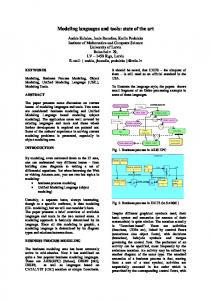
Modeling Languages
Domain models are defined in terms of modeling languages. These languages can be of various kinds, sometimes general enough to represent any system, or sometimes being very specific to capture only parts of a system, or only specific types of systems, or only some specific aspects or views of a system. An example of a general modeling language is the Unified Modeling Language (UML) [5], which has been defined for modeling software systems. On the other hand, more specific languages are called Domain-Specific Modeling Languages (DSML). Their advantage is that they abandon generality to the profit of a better expressivity, as they have been specifically constructed for adequately representing the knowledge of a precise domain. One drawback however is that several DSMLs are most of the time needed to cover all aspects of a system, thus increasing the cost to build tools to manipulate models of these languages. As will be seen later, the languages developed in this work belong to the DSML category, so it is worth taking some time to introduce their structure and the means that were develop for their definition. These notions are taken from Bézivin [19], where he proposes a vision of the development of MDE based on lessons learnt in the past 30 years in the development of object oriented technology. He compares the two relations at the heart of object oriented programming (instance, inheritance) with two similar relations of MDE (representation, conformance). These two latest relations are depicted in Figure 2-5, which represents the OMG Meta-Object Facility (MOF), where 4 levels of models are defined. The first level (M0) corresponds to reality (referent according to Rothenberg), which is represented by a model at the next level (M1). This model and the upper levels belong to a closed meta-modeling architecture where every model element on every layer is strictly in correspondence with a model element of the layer above. The model is said to conform to a meta-model, which is a model of a particular set of the possible conforming models. Like for the M1 model, the M2 model conforms to another model (M3 for Meta-Meta-Model), which conforms to itself thus closing the architecture. The power of the MDA framework actually comes from this M3 level, because it allows for building coordination between models based on different meta-models. One examples of such coordination is model transformation between models of different meta-models, but there are many others like model weaving, which deals with associating elements of different meta29
models. As a matter of fact, a promising research domain deals with the modeling of this coordination between models. It refers to the concept of mega-model, which is a model whose elements are models, including the representation of the specific relations between these models such as transformations, association, etc.
Figure 2-5: The Model-Driven Architecture organization (from [19]). 2.4.3
Natural versus Modeling Languages
Finally, a comparison of natural and modeling languages can be useful in the frame of this work. A major difference between these two types of languages is their semantics, which is much more precisely defined in modeling languages than natural languages. Indeed, a modeling language precisely states domain concepts in terms of classes, attributes and relations, which have a unique interpretation as opposed to natural language. Precision must be distinguished with level of abstraction. A model is always precise, at least enough to be understood by a computer program, independently of the level of abstraction of the represented reality. This required precision / semantics of course limits the expressiveness of the language compared to natural language. This will further be discussed in this document from the comparison of two representations of a requirements specification in terms of natural and RDAL languages, demonstrating that modeling language can have tremendous benefits and allow discovering errors that cannot be detected as easily from natural language specifications.
2.5 Architecture Description Languages A specific category of DSMLs is the Architecture Description Languages (ADLs), which are 30
dedicated to the modeling of systems architectures, for software, hardware, or both types of systems. As mentioned earlier, the commonality between these languages is that they all provide means to model the minimal set of elements needed to represent the architecture of systems, as identified by the definition of a system of [15], introduced section 2.1.1. However, these ADLs still differ in many aspects, especially in their semantics which is often refined for a specific domain. Some of the most well known of these ADLs are briefly introduced in the following sections. 2.5.1
UML
The Unified Modeling Language (UML) [5] is a general purpose modeling language for object oriented design authored by the OMG and initially created for the modeling of pure software systems. UML provides several diagrams to express different views of the system under design. Class diagrams provide a structural entity-relationship view of the system. Use case diagrams are used to outline the operational view. Sequence diagrams complement use case diagrams through interaction scenarios. State machine diagrams provide a behavioral view of the system. While UML is well suited for classical software design, a widespread criticism is that it is not well adapted for hardware modeling. However, UML can be extended to cover more specific domains. This is achieved by the definition of profiles, which consist of stereotypes providing additional attributes that can be affected to UML classes, tagged values and constraints. 2.5.2
SysML
An example of a UML profile is the Systems Modeling Language (SysML) [6], which is a standard for Model-Based Systems Engineering. SysML reuses a subset of UML including behavioral diagrams such as use cases, state machine, sequence and activity diagrams, and the package diagram. It provides a new requirements diagram with new structural diagrams such as block definition, internal block and parametric diagrams. The main structural concepts of SysML are centered on the concepts of blocks, ports and flows, which are used to model systems, system components (hardware and software), items that flow between them, conceptual entities and logical abstractions. The behavior concepts are all reused from UML to describe use cases, use case scenarios (activity or sequence diagrams) and block state transitions (state machines). Of particular interest for this work is the SysML requirements diagram, which allows the modeling of system requirements and their traceability to the design (blocks diagrams), and the parametric diagram, which allows the modeling of system analysis through constraints blocks, and the Quantities Units Dimensions Values annex (QUDV), which allows detailed modeling of quantitative properties. All these SysML concepts are introduced in greater details in chapter 3 which presents a state of the art for the contributions of this thesis. 2.5.3
MARTE
The Modeling and Analysis of Real-Time Embedded Systems (MARTE) [9] is another UML profile that adds to UML the capability of modeling and analyzing embedded systems. Besides software, which is well covered by UML, it allows the modeling of hardware components, and the definition of a mapping of software components onto hardware components with an allocation model to constitute a PSM. 31
MARTE provides support for high level specifications and detailed design of real-time embedded systems. It provides facilities to annotate models with information required to perform specific analysis, including performance and schedulability analysis. It also defines a general framework for quantitative analysis which intends to be refined / specialized to provide any other kind of analysis. 2.5.4
AUTOSAR
The Automotive Open System Architecture (AUTOSAR) language [10] was created for the development of complex electronic systems for the automotive domain. The standard defines a meta-model, which allows to model software architecture components and their interfaces. AUTOSAR separates the software and hardware components to allow components reuse and supports the modeling and analyzing of: 1. Functional safety (e.g. memory partitioning, program flow control, end-to-end library). 2. Multi-core. 3. Application / vehicle mode management. 4. Variants (for product line engineering). 5. Timing. 6. Standardized application interfaces. The principal aim of the standard is to master the growing complexity of automotive electronic and software architectures. It has already been used in major development projects and it has resulted in substantial savings in the overall costs [10]. 2.5.5
AADL
The Architecture Analysis and Design Language (AADL) is the ADL that has been used to illustrate the contributions of this thesis. For this reason, it is introduced in greater details than the other ADLs previously presented to ease the understanding of the modeling examples of chapters 6 and 8. 2.5.5.1 Components AADL is language standardized by the Society of Automotive Engineers (SAE) [7] based on components. Components are separated into four distinct types. Application software components are used to model the logical view of a system and are subdivided into the following sub-categories: A process represents a protected memory address space. A thread represents a unit of concurrent execution. A thread group represents a compositional unit for organizing threads. A data represents data types and data structures that can declare operations through subprogram access. A subprogram represents callable sequentially executable code. A subprogram group represents a compositional unit for organizing subprograms. 32
Execution platform components (hardware) are used to model the hardware resources of a system, and are subdivided into the following sub-categories: A processor is an abstraction of hardware and software resource that can schedule and execute threads. A virtual processor represents a logical resource that is capable of scheduling and executing threads, and other virtual processors bound to them. It allows representing hierarchical schedulers scheduling threads and/or virtual processors bound to them. A memory represents a component that stores data and code. A bus represents a component that connects execution platform components and implicitly embeds the necessary communication protocol and resources. A virtual bus is a logical bus abstraction such as a virtual channel or communication protocol. It can be bound to buses, virtual buses, processors, virtual processors, devices, or memory, which further determines what is represented by the virtual bus. A device represents a component that interfaces with the external environment such as peripherals. Abstract components are components that can contain any component and can be contained in any component. They are typically used to provide a place where information pertaining to a high level of abstraction can be stored. They are meant to be refined into one of the concrete component categories and must then obey the composition rules of the refining component. Finally, system components can be used to represent an assembly of interacting subcomponents, according to the definitions of systems previously introduced in this chapter. AADL systems can have modes representing different configurations of sub-components and their connectivity and properties. 2.5.5.2 Component Types and Implementations AADL components are represented by type and implementation (classifier) declarations. A component type declares the externally visible features of a component such as its ports, accesses to shared data or to buses, subprograms, etc. Implementation declarations define the internal composition of a component through contained subcomponents declarations. Component types and implementations can be extended to support successive refinements of components to provide a hierarchy of decreasing levels of abstraction. In a similar way, the type of a subcomponent can be refined into a more specific type being an extension of the original type thus preserving the defined characteristics and providing additional ones. 2.5.5.3 Component Interactions The interaction of components in AADL is represented with features, shared access and connections constructs. Features and shared accesses are declared in component types and can consist of: Event ports for communication of events raised by subprograms, threads, processors, or devices that may be queued. Data ports for typed data transmission among components without queuing. 33
Event data ports for message transmission with queuing. Subprogram access for access to a subprogram to be called from other components. Subprogram group access representing sharing and required access to a subprogram library. Parameter features representing data values that can be passed into and out of subprograms, and typed with a data classifier reference. Data access representing communication via shared access to data. Bus access representing physical connectivity of processors, memory, devices, and buses through buses. Abstract features representing placeholders for concrete features, i.e., ports, parameters, and the different kinds of access features. Abstract features are typically used in incomplete component type declarations, especially those that play the role of a template. Connections can be declared between features of subcomponents to enable the directional exchange of data and events among component, the access top bus or data components or the exchange of parameters of subprogram calls. 2.5.5.4 Declarative and Instance Models The part of AADL that has just been described above is called the declarative meta-model. Besides, AADL also provides an instance meta-model, which allows the modeling of instantiated systems where all components are contained in a single tree. An instantiated system is automatically generated from its declarative specification. The purpose of this is to provide a model that is easier to process by analysis tools, since there is no need to search for the subcomponents declared in distinct component implementations often located in different files. 2.5.5.5 Properties AADL includes a comprehensive sublanguage for modeling properties. Property types are defined at the M1 level (Figure 2-5), and contained in property sets. The core language includes a set of predefined properties to support main analysis domains such as schedulability, latency, resources allocation, etc. Because properties are defined at the M1 level, users can define new properties of their own for specific analysis needs. AADL properties can be of various types such as numbers with units, enumerations, references to AADL elements, etc. However, the coverage of the quantitative domain remains limited compared to that of other languages such as SysML. An important feature of AADL properties that has inspired the semantics of the languages of the work of this thesis is their visibility mechanism. Property values in AADL components can be declared in several places in a specification; component classifiers (type and implementations), subcomponents of a given classifier, instance components of the instance model, extending classifiers, refined subcomponents, etc. When values of the same property type are declared in several of these components (type, implementation, subcomponent, instance), a mechanism must be defined, with a search algorithm to determine which value is going to be used. For example, a property value declared in a component type is automatically visible from all its implementations, extending components, the subcomponents of its type, etc. The algorithm to 34
search for a property value is specified in Figure 2-6. From the given contexts identified by the numbered circled, the search consists of first looking if a value is set at the specific context. If no value is set, then the place with the following number in increasing order must be search and so on.
Figure 2-6: The search order for evaluating AADL property values (from the SAE AADL specification [7]). The advantage of this mechanism in that it nicely provides several places where property values can be declared, according to the level of abstraction of the information represented by the property. 2.5.5.6 Extensibility An important asset of AADL is its extensibility, which is essential for meeting project or domainspecific needs. Two extension mechanisms are provided. A first one consists in the addition of user-defined property sets and packages declaring new properties and component classifiers to constitute a so-called user extension. These classifiers are to be used as library of components for the modeling of other components. The second mechanism is the definition of new sublanguages in the form of annexes to extend the semantics of the AADL core language. An annex must be defined with great care and approved as part of the language by the SAE AS-2C subcommittee. This is not always an easy process as was experienced by the development of RDAL, which is in the process of being adopted as an annex of AADL for requirements engineering support. 2.5.5.7 System Architecture Virtual Integration To complete this presentation of AADL, the System Architecture Virtual Integration (SAVI) paradigm [8] is introduced. SAVI has been initiated by an international consortium of aerospace companies and government organizations. The goal is to achieve affordable development costs of safety-critical complex systems through the paradigm shift of “integrate then build”, pursuing the objective to build correct by construction systems. SAVI is driven by the following key concepts: An architecture-centric model repository covering many aspects of the system as the “single source of truth”. A component-based framework for model-based engineering. A model bus for maintaining a consistent model repository and for tool interchange. An architecture-centric acquisition process throughout the system life cycle that is supported by industrial standards and tool infrastructure. 35
The model repository makes use of several modeling languages, including ADLs such as AADL and SysML to represent the multiple aspects of the system to be built with the adequate formalism, as illustrated in Figure 2-7. This model-based development process encompasses both systems engineering and embedded software systems engineering.
Figure 2-7: Collaborating engineering using various modeling languages (from [8]). The model bus provides a data interchange mechanism between model repositories and the formats acceptable by analysis and generation tools. This integration of tools is facilitated by the use of standardized interchange representations for the models. It enables more effective integration checks by leveraging existing tools and minimizing the number of transformations towards tool proprietary representations. Virtually integrating and analyzing systems from their integrated models before physical integration allows for discovering many software/system integration issues at design time. Various system interface and sizing analyses can be performed on the integrated models by tools of various natures, sometimes operating directly on the AADL models like models represented with QAML, or otherwise taking as input a model conforming to the input format of the analysis tool, which must then be generated from the AADL models and transferred via model buses. 2.5.6
Comparison of the ADLs
The previous sub-sections have briefly introduced the main ADLs for the modeling of embedded systems, by emphasizing on the AADL which has been used for this work. In this section, a comparison of these languages along the axes of intended uses and modeling domains is presented, as illustrated in Figure 2-8. Recalling that one purpose of MBSE is the analysis of models, and that our domain is the embedded systems, UML is clearly inappropriate as it only considers software systems. It is only by extending it with the help of profiles such as SysML and MARTE that concepts for respectively system engineering and embedded systems can provide more semantics to the language. However, SysML still remains too general for the embedded systems domain, preventing important analyses to be performed due to the lack of semantics. As a matter of fact, the only way to provide enough semantics in SysML by distinguishing 36
components according to their categories (processor, memory, thread, subprograms, etc) is to extend the language with stereotypes for these categories. However, the risk is no standardization of these stereotypes and reduced interoperability between organizations.
Figure 2-8: Various ADLs and their characteristics in terms of intended use and domains (from [21]). Hence, only MARTE and AADL are adequate for the analysis of embedded systems. Between these two languages, AADL has a stronger semantics than MARTE, which is essential for model analysis and code generation. In addition, the fact that AADL is implemented as a DSML makes the language simpler by providing the exact needed constructs for the domain, instead of reusing the features of UML, which are not well tailored for specific domains. In addition, using UML tends to make the language more complex by automatically inheriting all features of UML, which may not be needed for the embedded systems domain.
2.6 The Open-PEOPLE Project Finally it is not possible to end this background chapter without a brief introduction of the OpenPEOPLE project [12], which supported most of this work. The purpose of the project was to provide an infrastructure for the analysis and optimization of the power and energy consumption of embedded systems, and for the development of power consumption models to be used in MBSE designs. Numerous power analysis models of all kinds were expected to come out of this project, and means to easily integrate them in model-based design tool chains were required. The power consumption models of the project are constructed following the Functional Level Power Analysis (FLPA) method [22], which has been developed at the Lab-STICC. As illustrated in Figure 2-9, the method consists in identifying a set of functional blocks impacting the power consumption, and to use them to define the model. The component under characterization is stimulated to vary each parameter on which the consumption depends, and measurements of 37
the drawn current are taken on the hardware platform. The model is then extracted from these measurements and represented by either a set of analytical functions, or a multidimensional data table. Once the model is built, the estimation process consists of extracting from the design the appropriate parameter values that are injected into the model to compute the power consumption.
Figure 2-9: The Functional Level Power Analysis (FLPA) method (from [22]). 2.6.1
Open-PEOPLE Needs for a Formalism to Represent Analysis Models
While the FLPA method has the advantages of producing models of a high accuracy that are fast to execute compared to low level simulations, its major drawback is a reduced applicability of the models. Because they are based on measurements on the targeted component, the resulting model is often specific to this component type, if not specific to the component instance itself. As a result, many models must be defined and managed. As a matter of fact, such power consumption models could ideally be shipped as part of a component’s data sheet. A dedicated formalism would then be needed to express such complex model and ease their integration in CAD tools. However, during the definition of QAML, it was soon realized that the scope of analysis can be much wider than power consumption, which is why the language was made generic enough to represent analysis for any quantities. 2.6.2
Open-PEOPLE Needs for Modeling Requirements
In addition, it was soon realized by partners of the Open-PEOPLE project that means to verify and optimize the AADL designs were required and missing. For example, once power consumption had been estimated with results valued in properties design components, users would also want to define constraints on these results, for example to verify that a given component never consumes more that a given power value, to meet requirements on autonomy or capacity of power supply. 38
Such verification is typically performed by annotating the models with constraints expressed with dedicated languages such as OCL [23] or Lute/REAL [24]/[25] for AADL. However, modeling only constraints is not sufficient. Even though some work on constraints had already been done in a PhD thesis of the Lab-STICC [26], it was felt that other crucial information than the plain constraints was required to be documented, for better traceability of the constraints. Information such as why the constraint exist, what are the assumptions for this constraint to hold, who has the need for such constraint, etc. may be as much important as the constraint itself. Indeed, as explained in chapter 3, several system faults have occurred simply because assumptions and rationale for a constraint had not been documented. The assembly of a constraint and these other information typically constitute a requirement, whose purpose is to bind these aspects under a single construct. While for the Open-PEOPLE project, only requirements constraining non-functional properties of the system (such as power consumption) needed to be represented, it was found that developing a comprehensive language for requirements engineering would be better since it would benefit the entire AADL community.
2.7 Conclusion The purpose of this chapter was to introduce the background concepts needed to provide a perspective for better understanding of the contributions of this thesis. Fundamental concepts such a system, system architecture, systems engineering, model, modeling, modeling language, architecture description language, model-driven engineering and model-based system engineering have been introduced. It was shown how the two contributions of this work are part of the systems engineering process, within the modeling process, and in the architectural and analytical paradigms. Next, the most common architecture description languages building upon these concepts were introduced, with an emphasis on the AADL, which has been used to exercise the contributions of this thesis. Finally, the Open-PEOPLE project was presented to understand the context in which the need for doing this work was originally discovered.
39
40
3 State of the Art Following the introduction of the fundamental concepts of MBSE, this chapter presents a detailed state of the art for the two contributions of this thesis, related to the domains of Model Based Requirements Engineering (ModRE) and NFP analysis modeling languages for embedded systems. First, a short introduction to Requirements Engineering Management (REM) is presented. Then, Model-Driven Requirements Engineering in support of REM is introduced by presenting the main modeling languages for RE. SysML requirements [6], the KAOS method and language [3] and the User Requirements Notation ITU standard are introduced with the identified issues. Finally the state of the art for quantitative analysis modeling is presented for SysML, the attribute language of Sentilles et al. [31], the ACOL language [32] and the MARTE Non Functional Properties (NFP) and Generic Quantitative Analysis Modeling (GQAM) [9]. It is through the study of these languages that both RDAL and QAML could be developed by reusing the best ideas from them while trying to solve their identified problems.
3.1 Requirements Engineering Requirements Engineering Management (REM) is a discipline of dealing with the management of requirements throughout the life cycle of a product. It is of primary importance since a requirements specification is the main artifact used to evaluate the success of a development project, whatever the domain may be (pure software, embedded systems, mechanical systems, etc.). This is performed by verifying that the developed product meets its requirements. To allow such verification, the requirements must be specified with some means, often using natural language documents or even better with a domain-specific language. The requirements specification can then be evaluated against the system that has been developed to ensure that it meets its requirements. The capture and analysis of requirements is therefore an essential activity in any system development process. It is not an easy task, since it often starts with ill-defined and conflicting ideas of what the proposed system is to do, and must progress towards an agreed, detailed, technical specification of the system. The requirements must consider not only the system to be built, but also its environment, as it describes how this environment shall be affected by the system for each context of operations. In addition, it involves a large diversity of stakeholders such as domain experts, designers, developers, marketing, etc, which are not used to work with the same methods and tools. As a result, the requirements description must be suitable for all these people, while remaining understandable by tools to help validate the requirements. The REM activity, which occurs at the very beginning of a project, is typically divided into five sub-activities or steps [27]: elicitation, modeling, analysis, validation / verification and management. 3.1.1
Elicitation
The elicitation of requirement occurs at the very beginning of the design cycle and requires negotiation among all stakeholders of the project, from the future users of the system to be built (or to evolve) to the people responsible for building and marketing the system. One difficulty of this activity is to define requirements that are consistent, complete and precise enough to be verifiable once the system is implemented. Requirements elicitation is typically performed by developing use cases scenarios for the system to discover its functions, which 41
must then be agreed by all stakeholders. 3.1.2
Modeling
Once requirements have been defined, a modeling phase can start using an adequate formalism. The purpose of this phase is to support the next phase which consists of analyzing the requirements specification to reveal errors that may not have been perceived during elicitation. 3.1.3
Analysis
The purpose of analysis is to evaluate the global quality of the requirements specification. This phase will allow revealing defects such as ambiguities, inconsistencies, incompleteness, etc., which often result from misunderstanding stakeholder needs, unresolved conflicts or incompleteness’s regarding the assumptions on the environment of the system. 3.1.4
Validation / Verification
Validation consists of checking that the requirements specification really corresponds to stakeholder needs. It is therefore a subjective activity since it always involves people. This activity is followed by a verification activity used to show that the system design specification meets the requirements. To support these activities, the requirements will need to be closely linked to the design specification and other artifacts. 3.1.5
Management
The management of requirements mainly concerns the way requirements are organized and linked to other requirements or artifacts from which they origin such as external regulatory or certification documents, etc. Other aspects deal with requirements uncertainty with respect to change, and requirements evolution in time and through product families. Tools and techniques such as traceability management and views are defined to better manage requirements specifications. Indeed, organizing requirements specifications properly is important since complex systems may include thousands of requirements with several levels of hierarchy. Modeling, which was introduced in the previous chapter, can greatly help in performing these activities, by providing a more precise description of the artifacts than natural language specifications. This has the advantage of reducing ambiguity, while still representing the artifacts at the adequate level of abstraction for the activities to be performed. 3.1.6
Current Industrial REM Practices
These activities, which form the basis of REM, are always needed whatever the project is. However the way they are performed can vary a lot in the industry, as was found by an interesting study conducted by Lempia and Miller for the Federal Aviation Administration (FAA) Airport and Aircraft Safety Research and Development Division [28]. This study of practices from both the industry and literature served as a basis for the authors to define a set of 11 REM best practices as introduced in section 3.1.6.2. The results of the study are presented in the REM Findings Report and the best practices in the REM Handbook. These two documents are briefly presented in the following sections. 3.1.6.1 The FAA Requirements Engineering Management Findings Report In 2008, the FAA subcontracted a study to determine methods to enable successful 42
management, control, integration, verification, and validation of system and software requirements. The study included two phases. The first phase consisted of a survey of both the literature and industry practices to identify best practices in requirements and issues and concerns of practitioners. 3.1.6.1.1 Results from the Literature Search The FAA literature survey, although it was not complete as it missed important RE languages and methods introduced later in this state of the art, still allowed discovering that despite the various REM best practices for safety-critical systems (Software Cost Reduction (SCR), Consortium Requirements Engineering (CoRe), Specification Toolkit and Requirements Methodology (SpecTRM)), important issues in REM remained. These issues include clearly defining the system boundary, documenting all environmental assumptions, supporting development by multiple entities, providing intent and rationale, supporting the validation of requirements, managing change and complexity, specifying Human Machine Interface (HMI) requirements, and supporting the verification of requirements. Helping in solving these issues has been the intent of the RDAL language, as will be presented in chapter 5. 3.1.6.1.2 Results from the Industry Practices Survey The industry practices survey showed that the majority of respondents capture requirements in natural language, using tables and diagrams with tools such as IBM Rational DOORS or word processors. Object-oriented approaches such as UML are starting to be used, but to a lesser extent and primarily for software requirements. One of the most surprising finding of the study is that 14 years after the publication of the DO178B [29], which is a standard dealing with the safety of software used in airborne systems, there are still many questions on how to specify and manage requirements within a DO-178B process. In addition, it also appeared that the best practices identified in the literature search are being used only rarely. Even the object-oriented approaches for requirements elicitation and documentation do not appear to be widely used by the survey respondents. Finally, and surprisingly, the survey respondents raised very few concerns related to several of the key issues identified in the literature search, including how to specify the system boundary, how to identify and document environmental assumptions, how specify the intent of requirements, and how to specify requirements for the HMI interface. 3.1.6.2 The FAA Requirements Engineering Management Handbook The second phase of the study consisted in using the findings of the first phase to guide the selection of several best practices from the literature and industry practices. A set of 11 practices were selected and documented in the REMH [20]. The best practices are summarized in Table 3-1. More details on these practices will be given as the RDAL language is introduced, when showing how the language was constructed to support these practices. Practice # 1
Title
Develop the System Overview
Summary of Practice
Provide a high level view of the system to be developed describing its purpose, how it interacts with its environment, and why the system is needed.
43
2
Identify the System Boundary
Provides a sound understanding of what lies within the system to be built and what lies within the larger world. Define the exact interaction of the system with its environment through monitored and controlled variables.
3
Develop the Operational Concepts
Provide scripts or scenarios that describe how the system will be used. Used to discover the system function and the context in which these functions are used.
4
Identify the Environmental Assumptions
Identify the environmental assumptions on which a system depends for its correct operation. These can be specified as a mathematical relationship between the controlled and the monitored variables. This relationship can be as simple as the types, ranges, and units of the monitored and controlled variables.
5
Develop the Functional Architecture
Organize requirements into functions that are logically related with minimal dependencies between the functions to enhance readability of the requirements and to make them robust in the face of change. Break down functions into smaller sub-functions to allow the requirements to scale for large systems.
6
Revise the Architecture to Meet Implementation Constraints
Revise the ideal functional architecture early to meet implementation constraints such as those related to safety or to the need to integrate with legacy systems. Start from the previously developed ideal functional architecture and iterate to develop an architecture that addresses these constraints. This architecture is then used as the framework for organizing the detailed requirements.
7
Identify System Modes
Modes define discontinuities in the system behavior that are visible from the operators or other systems. Identify these modes to simplify the specification of the detailed requirements.
8
Develop the Detailed Behavior and Performance Requirements
Produce a complete and consistent set of detailed system requirements that define how the system must change the controlled variables in response to changes in the monitored variables. Specify the value of the controlled variable for each system state and inputs, the allowed tolerance about this value, and performance characteristics such as the allowed latency.
9
Define the Software Requirements
Define software requirements that map directly to the system requirements and their architecture as a straightforward extension of the system requirements.
10
Allocate System Requirements to Subsystems
For large systems, allocate requirements to subsystems that can be developed independently by subcontractors, in a manner that is consistent with the other recommended practices.
11
Provide Rationale
Provide proper rationale documentation on why each requirement or environmental assumption exists or why a particular value or range is specified.
Table 3-1: The eleven best REM practices of the REMH [20]. An important asset of the REMH practices is that they can be introduced incrementally in an 44
organization’s existing requirements engineering process, without the need to completely change the process. This requirement, when not met by new methods and tools very often prevents their adoption by the industry.
3.2 Model-Driven Requirements Engineering The previous section introduced the REM discipline through a brief description of its main activities and current practices. It was pointed out how modeling can help in these practices. As a matter of fact, modeling requirements helps in improving the quality of requirements specifications as much as modeling the system architecture helps in improving the quality of the design. In addition, extra benefits emerge from the composition of requirements and design specifications by bridging the gap between requirements and design. Many requirements modeling languages already exist for these purposes and the most well known are introduced with a discussion on their strengths and weaknesses. 3.2.1
SysML Requirements
3.2.1.1 Overview The SysML [6] is one of the most used languages for modeling requirements in the embedded systems industry. This OMG standard has already been implemented in well known tools such as TOPCASED [33], the Enterprise Architect commercial UML tool [34] and the Eclipse Papyrus UML modeler1. SysML provides stereotypes to represent requirements and test cases, and a set of predefined traceability relations between requirements and other elements such as other requirements, use cases or design elements (blocks). A SysML requirement has a text attribute to store its expression in terms of natural or formal (OCL) language. SysML design elements can be linked to requirements through a satisfy relation. When OCL is used, a requirements expression can be evaluated against design elements to verify the requirement. Several requirements relationships are provided in SysML to enable relating requirements to other requirements, as well as to other model elements. These include relationships for defining a requirement’s hierarchy through decomposition, deriving requirements, verifying requirements, and refining requirements. Decomposition implies that all sub-requirements must be met for the parent requirement to be met. Derivation relates a requirement to its source requirement, generally corresponding to requirements at the next level of the system hierarchy. A simple example may be a vehicle acceleration requirement that is analyzed to derive requirements for engine power, vehicle weight, and body drag. The verify relationship defines how a test case or other model element verifies a requirement. A test case can be used as a general mechanism to represent any of the standard verification methods for inspection, analysis, demonstration, or test. A verdict property of a test case can be used to represent the verification result. The refine requirement relationship describes how a model element or set of elements can be used to further refine a requirement. For example, a use case or activity diagram may be used to
1
The latter is currently replacing the original TOPCASED UML tools.
45
refine a text-based functional requirement. Alternatively, it may be used to show how a textbased requirement refines a model element. Requirements and relationships make use of the generic rationale stereotype of SysML, which can be attached to any requirements relationship or to the requirement itself. For example, a rationale can be attached to a satisfy relationship that refers to an analysis report or trade study that provides the supporting rationale for why the particular design satisfies the requirement. Similarly, this can be used with the other relationships such as the derive relationship. 3.2.1.2 Limitations While SysML covers the most important concepts needed for RE, it turns out to be difficult to use with a system architecture language other than SysML block diagrams. SysML requirements cannot be directly traced to system architecture model components from other languages than UML. For example, the satisfy link between requirements and design elements are targeted to UML Named Elements, and SysML requirements cannot be used with non UML based languages such as AADL. The only possible way would be to define an external trace model between SysML and AADL, with the drawback of importing the entire UML while only a small part of SysML is really needed. Furthermore, SysML lacks means to bridge requirements to design. Only the basic satisfy relationship is provided, which is clearly not sufficient. Means to define views on the design is required. For example, there are cases where all components of a given category (say all processors) may be required to verify a given requirement. Having to select the components from the design model manually would then be particularly tedious and errors prone as design models are evolving. As new components would be added or removed, the trace would always need to be maintained. Another issue concerns the expression of requirements. An asset of SysML requirements is that at least they can be expressed formally as OCL constraints. However, while expressing constraints with OCL may be practical for UML, it turns out to be much more difficult for AADL models, mostly due to the complexity of the structure of the AADL property meta-model. As explained in chapter 2.5.5.5, an AADL property is not simply defined as a property at the M3 level (such as a property of a class), but as a set of objects at the M2 level whose structure is contained in components. As a matter of fact, writing OCL constraints for an AADL model is only manageable after a large set of query libraries is provided to define an appropriate API. It turns out to be much easier to define AADL constraints with the REAL language [25], as it provides a set of predefined constructs for querying AADL model elements. Furthermore, the semantics of the SysML requirements-to-requirements traceability relationships (composition, refinement, derivation) is not always clear. While the semantics of requirements composition is quite clear (the parent requirement is only verified if all of its composing child requirements are verified), the meaning of other relationships such as derivation must be clarified. Moreover, other relationships such as refinement may be interpreted in different ways depending on users. For example, the SysML refinement is typically used to represent the refinement of a requirement through a use case, but it has also been used to model design alternatives [36], similar to the KAOS method introduced later. Clarification of the meaning of these relationships is definitely required. Finally, important constructs are missing to support REM best practices such as those prescribed 46
by the REMH. For instance, there is no construct such as preliminary system goals, environmental assumptions, stakeholders, traceability with respect to change, and means to formalize the system overview and system boundary. 3.2.2
The KAOS Method and Language
3.2.2.1 Overview KAOS, which stands for Keep All Object Satisfied, has been developed in the 90’s and is issued from collaborative research between the University of Louvain in Belgium and the University of Oregon in the United States. It is part of the Goal-Oriented Requirements Engineering (GORE) methods. KAOS is implemented in a tool called Objectiver developed by Respect-IT, a spin-out company of the University of Louvain. KAOS has been put to practice on dozens of industrial cases in different sectors. The principal artifact in a KAOS model is a directed acyclic graph of goals, where the top-most elements are business and strategical goals expressed in terms of the stakeholders’ vocabulary, and progressively refined into sub-goals expressed in more and more technical terms. At the leaf of the graph are requirements, which are special goals attached to agents of the system under design. Agents are design components responsible for meeting the requirements. Like for SysML requirements, goals can be refined, into a set of refinements that can refer to one or more sub-goals as illustrated in Figure 3-1. Each refinement describes a way of achieving the parent goal thus representing design alternatives. A refinement decomposed into several subgoals is equivalent to a SysML requirement decomposed into sub-requirement; each of the subgoals must be achieved for the parent goal of the refinement to be achieved.
Figure 3-1: A KAOS goal model showing several refinements (yellow circles) to achieve the same goal (from [38]). An important asset of KAOS is that concepts such as assumptions (expectations), domain properties, obstacles and goal conflicts are explicitly represented in the language. As a matter of fact, many of the RDAL constructs have been inspired from the KAOS language. 3.2.2.2 Limitations As illustrated in Figure 3-2, the KAOS language is composed of several sub-languages for 47
modeling other concerns such as responsibilities, operations and entities. While this organization has the advantage of providing a nicely integrated set of sub-languages, it has the disadvantage of imposing to users the choice of KAOS for modeling the design. When another language such as AADL must be used, model transformations are required, which results in duplication of information. As explained in [39], using KAOS with AADL requires the use of model transformations from KAOS to AADL, thus introducing the complexity of model synchronization and the risk of model inconsistencies, which could favor the “multiple truths in analysis results” problem, causing system-level problems to remain late into the development life cycle [1]. In addition, like for SysML, constructs are missing in KAOS to explicitly identify from the requirements specification the system to be built, its environment and their interaction. The system and its environment are indeed only identified implicitly through the modeling of expectations, which are supposed to constrain agents from the environment. It will be seen in chapter 5 how RDAL improves this by providing explicit traceability links for the system boundary.
Figure 3-2: The KAOS language, its mains concepts and its sub-languages (from [38]). 3.2.3
The User Requirements Notation
3.2.3.1 Overview The User Requirements Notation [30], which is a standard of the International Telecommunication Union Study Group (ITU), is a semi-formal graphical GORE modeling language oriented towards goals and scenario modeling. It defines two sub-languages; the Goaloriented Requirement Language (GRL) for modeling intentional elements and non-functional requirements, and the Use Case Maps language (UCM) to express functional requirements as use-cases (Figure 3-3). Like for KAOS, the language is quite mature and implemented in the 48
jUCMNav tool [40], which is integrated into the Eclipse development environment. The GRL, which originates from the “i*” modeling language [41], includes concepts for modeling soft goals (goals that can never be entirely satisfied) [42], represented graphically as a cloud shape (top part of Figure 3-3). Like for KAOS, URN goals can be connected to each other via contribution links, which can be composed using “and” and “or” constructs. Contributions can be of various amounts, in a positive or negative way like in KAOS. Rationale modeling is quite enhanced in GRL, as justification of links can be declared in the form of beliefs illustrated as ellipses. Soft goals are typically refined until they become quantifiable goals or potential operational solutions. In the latter case, they are tasks shown as hexagons, which are similar to operations of KAOS.
Figure 3-3: The User Requirements Notation. Another asset of GRL is that an evaluation mechanism is available to measure the impact of decisions on the level of satisfaction of goals. From the level of satisfaction of tasks and low level goals, a propagation algorithm is used to compute the level of satisfaction of soft goals thus helping in making decision and tradeoffs among various strategies and designs. The second sub-language of URN, (Use-Case Maps), is well adapted for the modeling of scenarios used for discovering the functions that are required for the system to be built. A UCM diagram has the advantage of showing on the same diagram both the entities (actors or 49
systems) and the actions that they perform, in a quite compact notation (bottom part of Figure 3-3). An entity is represented as a box containing the performed actions, which are located along a path representing the action sequence or scenario. A path may have forks and joins for representing different action paths occurring upon some conditions. Calls to other use cases are represented as diamonds. This is particularly useful to model exception cases providing more details on how the entities respond to exceptions. The advantage of UCM diagrams is that they convey much more information than UML use-case diagrams, which must be refined by activity or sequence diagrams to provide sufficient details. Indeed, compared to UML, UCM diagrams show on the same diagram both the entities (actors or systems) and the actions that they perform. As will be seen in chapter 6, UCM turned out to be a nice fit to the modeling of the natural language use cases of the examples on which RDAL has been validated. Traceability points were added in RDAL to trace requirements elements to UCM models. 3.2.3.2 Limitations Like for KAOS, a disadvantage of URN is that it also includes elements for modeling the design in the requirements specification. Furthermore, there is no identified concept for functional requirements, which are implicitly embedded into use-cases in the form of use-case steps and other constructs. As a result, it is difficult to make a list of functional requirements, in terms of declarative statements verifiable against a design. Indeed, functional requirements in AADL are usually stated as expressions understood by verification tools such as model checkers or theorem provers, and verified against behavior descriptions attached to AADL components. 3.2.4
Discussion
This first part of chapter 3 introduced the REM discipline, by presenting the practices currently used in the industry. Then, model-driven requirements engineering was introduced as a means to support the capture analysis and management of requirements to improve their quality. Then, the three most well known RE modeling languages were presented. Despite these good languages, most MDD approaches still use only partially defined requirements models or even natural language for requirements, as pointed out in [43] and [28]. This could be due to the main issues that were identified for these languages: Not easy to use with existing ADL standards, either because they include constructs to model the design (KAOS, URN), or because they are meant to be used in a different technical space such as UML (SysML). No support for extensibility with respect to traceability and constraints languages. No support for some of the important REM best practices for embedded systems development. Semantics not always clear (e.g.: SysML traceability links and the reuse of UML constructs not always well suited for the domain thus increasing complexity).
3.3 Quantitative Analysis Modeling This subsection presents the state of the art for the second contribution of this thesis, which relates to quantitative analysis of embedded systems. The purpose of these analyses is to estimates system NFPs. The study of NFPs is part of a broad research domain for which a few 50
modeling languages have been developed, which can be compared to the QAML. For this reason, they are introduced in the following sections. 3.3.1
SysML Constraints Blocks
3.3.1.1 Overview SysML provides the constraint blocks construct dedicated to the modeling and integration of quantitative analyses in SysML block diagrams. Constraint blocks can be added to a diagram (parametric diagram) to specify a network of constraints that represent mathematical expressions constraining the physical properties of a system. An example of such network is shown in Figure 3-4, which is an example parametric diagram for modeling the dynamics of a vehicle. A constraint block (rounded corner square in the figure) represents a mathematical relationship between input parameters represented as squares at the edge of the block. These parameters can be connected to parameters of other blocks from where the value is to be taken (or set depending if it is an output parameter).
Figure 3-4: An example SysML parametric diagram for modeling vehicle dynamics (from [6]). A parametric diagram can be applied to a block diagram (design model) by binding properties of the design to parameters of the parametric diagram. An engineering tool can then take a parametric model and perform the calculations and optionally set the analysis results in property values incorporated back into the SysML model. The SysML specification does not enforce any specific language for representing the mathematical relationships between parameters. It can typically be expressed with OCL or possibly with MathML depending on the tool that will be used to compute the analyses. All these SysML quantitative analysis elements are built on top of the QUDV (Quantities Units Dimensions Values) annex for the modeling of quantities and units. Another purpose of parametric diagrams is to support sensitivity analysis, trade studies and 51
design optimizations. For sensitivity analysis, a block definition diagram defines the analysis context (design). Design property values can be varied to determine which property values have an impact on a given requirement. Trade Studies are used to compare alternative design solutions by making use of a set of Measures of Effectiveness (MOE). A MOE defines a property to be evaluated in a trade study with the help of an objective function. Objective functions are modeled as a kind of SysML constraint block with parameters of the function related to the MOE’s using parametric diagrams. The set of possible solutions for the trade study can be depicted as specialized blocks of a general block, with the general block defining all of the MOE’s (Figure 3-5). The specialized blocks provide different values for the MOE’s.
Figure 3-5: Using specialized SysML blocks to represent design alternatives (from [44]). A block is used to depict a trade-off (Figure 3-6), which references the possible design alternatives and contains the objective function that is used to evaluate the alternatives. Value properties are defined to capture the score of each alternative. Finally, a parametric diagram is used to relate the MOE’s to the parameters of the objective function (Figure 3-7). The objective function (score) specifies the overall value of each alternative.
Figure 3-6: A performance trade-off modeled as a SysML block (from [44]). The details of the cost function are not specified in this example. 52
Design optimization is modeled through the definition of an optimization function defining an overall operational effectiveness in terms of various MOEs. Lower-level parametric diagrams can be established for analyzing each MOE to provide a flow down from the top-level MOE to critical system properties.
Figure 3-7: A parametric diagrams relating the MOE’s to the parameters of an objective function for two design alternatives (from [44]). 3.3.1.2 Limitations The SysML constraint blocks provide an essential support for the modeling of quantitative analysis of SysML models. Again, the main problem for its reuse with AADL is that it is only usable with SysML block diagrams, which are part of the UML. For the AADL, whose technical space is that of the DSMLs, none of this is directly reusable. In addition, means other than mathematical expressions to describe the relationships between parameters are required. Look-up tables, often used to represent relationships not always easy to express in terms of a mathematical equation are needed as well, along with the ability to delegate the computation of the relationship to an external tool, to favor the integration of legacy analysis tools. Furthermore, uncertainty, though it can be modeled as constraints blocks, is not explicitly represented in the language. Uncertainty is a key concept for estimation models such as those of the Lab-STICC power consumption models, which are based on measurements requiring error analysis. 3.3.2
Non-Functional Attributes Modeling Language
3.3.2.1 Overview Another interesting work closely related to the modeling of quantitative analysis concerns the modeling of non-functional properties in component models. In [31], a language is proposed for the description of non-functional attributes based on an Attributable class that shall be inherited by all classes of the component design language (typically components, operations, connectors, 53
etc.) that can have non-functional attributes (Figure 3-8).
Figure 3-8: The attribute language meta-model and its integration with a component-based modeling language (from [31]). As illustrated in Figure 3-9, an attribute has properties such as a type (e.g. power consumption, execution time, etc.) declaring the attributable elements that the attribute can annotate, and a data format, including primitive (string, integer, real, etc.) and complex types. An attribute can have multiple values and meta-data to store information such as how the attribute value was obtained and its degree of confidence (Figure 3-10). An attribute value may also have a set of validity conditions, specifying for what type of context the attribute value is valid.
Figure 3-9: Types of attributes (from [31]).
Figure 3-10: Meta-data for attribute values (from [31]). Another important aspect is attribute value composition in terms of other attribute values, as 54
illustrated in Figure 3-11. The existence of hierarchical component models that also include composite components built out of other components influences the ways in which the values of attributes can be established. Ideally, all attributes of a composite component should be directly derivable from the attributes of its sub-components. While this is easily achievable for some attribute types, e.g., static memory usage and power consumption, others depend on a combination of many attributes of the sub-components, or even on other software architecture details.
Figure 3-11: Attribute composition (from [31]). According to the authors, attribute composition is the responsibility of the development process, which should specify when and how attribute values should be derived for composite components. They suggest an interesting alternative, for easily composable attributes such as static power consumption, which consists of including the specification of a composition operator in the attribute type registry. As will be seen in chapter 7, this later suggestion has been taken into account in the definition of the QAML. 3.3.2.2 Limitations While several characteristics of this attribute language are interesting, it is again not easy to use with existing architecture languages such as AADL. Indeed, it requires making the components of the language inherit the Attributable class. In addition, many of the characteristics of the attribute languages are already included in the AADL property language. An example of this is the attributable property of an attribute type, which is equivalent to the applicability clause of an AADL property definition. Furthermore, the language focuses on the description of the attributes, but not on how their value may be computed in terms of other attributes or properties of the design. Performing the analysis to compute the estimates is the responsibility of external analysis tools. From what was seen in the background chapter (section 2.6), the Open-PEOPLE project required a much more expressive language allowing to precisely state how attribute values are computed, whatever they are estimated or derived from the composition of other attribute values or characteristics of the design model. 55
3.3.3
ACOL
3.3.3.1 Overview Another interesting approach for the quantitative analysis of ADL models is ACOL [32]. It is an annotation language incorporating three types of expressions: analysis, constraint and optimization. The core language includes a set of principles that must be adapted to the ADL that it is be used with. However, like for QAML, the language has only been used with the AADL. These principles are illustrated in Figure 3-12.
Figure 3-12: The ACOL meta-model and its link with an ADL (from [32]). A sequence of related ACOL expressions is grouped under an ACOL implementation, and each ACOL implementation conforms to exactly one ACOL interface, which defines its view on the design model through ports. When an ACOL implementation is associated with a design model element, each port of its interface must be mapped to a design model element conforming to the type of the port. The mapping is restricted by the obligation to map ports only to elements visible from the annotated element, on the same or lower layers in the system hierarchy. This measure favors correct element annotation in terms of layering and information locality. ACOL analysis expressions allow defining properties derived from other properties (Listing 3-1). The values of these properties may be obtained from the ACOL interface of the implementation, which is plugged to an architecture component, using an annex clause for AADL. The principle of ACOL is to adapt its syntax to the actual syntax of the ADL it is used with. This explains the textual notation used when ACOL is used with AADL. The idea is to reduce the learning barrier for designers that are expected to be more comfortable with a notation close to the architecture language notation in use. 3.3.3.2 Limitations Like for the other languages presented previously, ACOL has many interesting features. However, it is not complete enough to represent all types of analysis models that need to be represented, as discovered during the Open-PEOPLE project. For example, lookup tables cannot be represented, and neither can calls to external analysis tools. In addition, the integration of analysis and constraints languages into a common language may not always be desirable. The principle of separation of concerns would favor using three different languages for the three 56
types of ACOL expressions, as they can be interchanged more easily depending on user habits and needs, and reused across various design languages. In addition, as will be seen in chapter 5 and 7 the concepts of constraints, analysis and optimization expressions would benefit from being represented from a wider perspective (constraint as the expression of a requirement, analysis clause as the evaluation descriptor of an analysis model, optimization clause as the expression of a measurable objective). analysis Scaled := Freq/5; Power := (3*Scaled)ˆ2; constraints Fail when {Freq < 100 MHz}; Fail when {Freq > 500 MHz}; Fail when {Power > 20 W}; optimizations Minimize => Power;
Listing 3-1: An example of ACOL implementation (from [32]). 3.3.4
MARTE Quantitative Analysis Modeling
3.3.4.1 Overview The MARTE UML profile [9], which was briefly introduced in chapter 2, provides two packages for the modeling of system architectures (design model) and their analyses (analysis model) (Figure 3-13). The analysis package uses the NFP and the Generic Resources Modeling (GRM) packages from the MARTE foundations to provide a Generic Quantitative Analysis Modeling (GQAM) package, which together serve as a basis for Schedulability Analysis Modeling (SAM) and Performance Analysis Modeling (PAM). These packages are briefly presented in the following sections. The MARTE profile is so rich that only the features required to compare with QAML are presented. 3.3.4.2 Non-Functional Properties The MARTE NFP package allows modeling qualitative and quantitative NFPs (Figure 3-14). Like SysML, NFP includes basic constructs for modeling dimensions and units of quantities. NFP values can be set in MARTE model elements in the form of annotations. Annotated elements are contained in an annotated model, which declares a set of modeling concerns referring to the relevant NFP declarations. NFP values can be constrained with three different types of constraints. Required constraints indicate a minimum demand on a quantitative or qualitative level (e.g.: a maximum latency for execution). Offered constraints establish the domain of supported NFP values for a model element. Finally, contract constraints define conditional expressions that specify relationships between offered and required non-functional values. Similar to the work of [31], the MARTE NFPs can be declared in type libraries for their used in models. The NFP constructs rely on the MARTE Value Specification Language (VSL) annex to 57
define expressions for the values and dependencies of NFPs through variables. Dependencies involving more than one model elements are expressed through constraints.
Figure 3-13: The architecture of the MARTE profile (from [9]).
Figure 3-14: The Nature package of the MARTE NFPs (from [9]).
58
3.3.4.3 Generic Resource Modeling The MARTE analysis constructs are based on the Generic Resource Modeling (GRM) package providing the concepts necessary to model platform resources for executing real-time embedded applications. These GRM constructs are refined in the design SRM (Software Resource Modeling) and HRM (Hardware Resource Modeling) packages to support design, and in the Generic Quantitative Analysis Modeling (GQAM), the Schedulability Analysis Modeling (SAM) and the Performance Analysis Modeling (PAM) packages to support analysis. A MARTE generic resource is a behavioral classifier that provides a number of resource services and declares provided and required NFPs. Resources in design are used to model the execution platform (hardware) from a structural point of view, while resource services are used to model the behavioral point of view (application). 3.3.4.4 Generic Quantitative Analysis Modeling The GQAM is meant to support the modeling of specialized analysis domains such as performance, schedulability, power consumption, memory, reliability, availability, and security. It provides foundation concepts shared by all these specialized domains. As shown in Figure 3-15, the central concept of GQAM is the analysis context, which represents the root of the domain model. It contains two parts that address different concerns: The workload behavior contains a set of related end-to-end system-level operations, each with a defined behavior, triggered over time as defined by a set of workload events. The resources platform is a logical container for the resources used by the system-level behavior represented in the previous model.
Figure 3-15: The MARTE GQAM package (from [9]). For a given analysis, the context identifies the model elements (diagrams) of interest and specifies global parameters of the analysis, which define the different cases being considered for the analysis, which may affect the parameters of behavior and resources (such as the number of repetitions of a sub-operation, or the size of a list). 59
The workload behavior package introduces concepts such as behavior scenario, which extends resource usage from the GRM package. A resource usage links a resource to its usage. A scenario includes a collection of steps, for which resources usage for their execution can be described. In other words, it is used to describe behavior with specific classes linked to the GRM so that information needed for quantitative analysis is represented. Finally, GQAM observers extend the NFP constraints to provide measures over a period of time, between user-defined observed events. 3.3.4.5 Usage of the MARTE Analysis Constructs The MARTE analysis constructs are meant to be applied to existing design models, on both the structural (class diagram) and behavioral diagrams (sequence diagrams, state machines, etc.). The design models are annotated with NFPs, SAM and PAM stereotypes so that these information can be used by external tools to perform the analyses. 3.3.4.6 Limitations The MARTE analysis constructs appear to be quite developed, even though they may seem complicated at a first glance. There are a few shortcomings such as limited units modeling compared to QUDV SysML, no construct provided to represent lookup tables / calls to external analysis tools, and no uncertainty (errors) modeling. Like for SysML, the MARTE NFP and VSL are part of a UML profile and do not fit in our technical space based on DSMLs. 3.3.5
Discussion
We have introduced three modeling languages for quantitative analysis of embedded systems. First, it was seen that the Systems Modeling Language (SysML) includes support to model quantitative analysis as constraints. Mathematical equations relating quantities can be declared for these constraints blocks with mapping between the input and outputs of the block and variables of the equation. These blocks are then connected between them to describe the association of block variables with variables of other blocks thus constituting a parametric diagram. A parametric diagram can then be applied to a block diagram representing the architecture by having its input / output variables associated to properties of the design. This provides essential support for sensitivity analysis, tradeoff studies and design optimization. The attribute language of [31] was then presented, which serves to model non-functional properties of architecture models, with extensive meta-data of these attributes (declaring how the value was obtained, under which condition, its accuracy, etc.). Composition of these attributes into a derived attribute can also be modeled to some extent. Next, ACOL [32] was introduced, which is a textual language for describing analysis, constraints and optimization expressions applicable to models of arbitrary ADLs. ACOL must be adapted to the ADL it is meant to be used with. To our knowledge, this was done for AADL only. Finally, the MARTE constructs for quantitative analysis were introduced, where a rich set of annotations are provided to be added to design models for being used by analysis tool to compute the results by evaluating VSL expressions of the NFPs. However, as was discovered during the Open-PEOPLE project, none of these languages could be used directly with AADL models: 60
MARTE and SysML suffer from their implementation in the UML technical space, which is not adapted for the DSML space. None of them includes constructs to integrate various means to compute estimations such as lookup tables or calls to external tools. None of them provides dedicated constructs for modeling uncertainty, which is an essential part of any estimated value. Only SysML provides complete quantities and units modeling constructs, and interesting support for sensitivity and tradeoff analysis and design optimization.
3.4 Conclusion This chapter first introduced the state of the art of model-driven requirements engineering by presenting the main requirements modeling languages such as the KAOS, URN and the SysML requirements package. It was seen that even though these languages have several qualities, none of them was directly usable in the DSML technical space. In addition, these languages do not provide all the essential constructs to support REM best practices such as those of the REMH. The verification of system non-functional requirements is based on the estimation of nonfunctional properties, which are computed through analysis models. State of the art has been presented for quantitative analysis embedded systems. It was shown that several approaches and languages exist to support these analyses such as the SysML, the non-functional attributes language of [31], the ACOL language [32] and the MARTE analysis package [9]. Like for the REM domain, it was observed that none of these languages is suitable for being used with AADL. In addition none of these languages contains all of the constructs that were required for power and energy analysis modeling as required during the Open-PEOPLE project. However, many interesting aspects of these languages inspired the development of the QAML language.
61
62
4 Global Languages Architecture 4.1 Summary This short chapter introduces the global architecture of the languages developed during this thesis. The basic principle that guided the design of the languages such as Multi-Paradigm Modeling (MPM) is first introduced. Next, an overview of the languages that compose RDAL and QAML is presented, with a short presentation of the modeling languages that are commonly used by both languages. Detailed information on these latter languages can be found in the SAE RDAL draft specification [45].
4.2 Multi-Paradigm Modeling The architecture of the RDAL and QAML languages follows a separation of concerns principle which consists of modeling with a Multi-Paradigm Modeling (MPM) approach. MPM advocates that every aspect of a problem should be formalized with an adequate formalism (typically a DSML). This is to ensure that all information relevant to the problem is precisely stated, at the appropriate level of details (abstraction). The danger is to leave important information implicit with the risk of leading to misinterpretation. This can easily be related to the example of the Ariane 5 rocket mentioned in chapter 1. In this case, the assumption that the software was appropriate for the range of acceleration values of Ariane 5 (much greater than for Ariane 4) obviously was not explicitly documented; as it let engineers reuse this software in an inadequate environment. Formalizing this information in a sufficiently precise way so that it can be verified by tools would have greatly help in preventing the error. In addition, MPM advocates that formalisms of orthogonal domains should be independent of each other, and limited in size to reduce complexity. This is achieved by introducing in the language only the artifacts needed for representing the domain at the adequate level of abstraction for the problems to be solved. This is not always the case for UML profiles such as SysML or MARTE, where UML constructs are reused for other purposes than the original one at the cost of adding additional complexity. A concrete example of this is a SysML requirement, which is represented within the UML as a stereotype applied to a UML class. However, a UML class can declare operations, which makes no sense for a requirement. As a result, an additional constraint must be added, as stated in the SysML specification, that the class shall not have attributes or operations, and should not participate in associations [6]. However, one identified challenge of MPM remains the integration / composition of all the involved languages.
4.3 Overall Languages Architecture The definition of the RDAL and QAML languages required the composition of many DSMLs, some of which were languages that already existed like the AADL (sometimes standardized), and others having been specifically created by myself for this work. Figure 4-1 depicts the overall language architecture, where each ellipse represents a distinct modeling language for covering a sub-domain of the more global domain of MBSE. The arrows between the languages indicate the composition dependencies of the sub-languages. They are 63
of three types: A use dependency corresponds to the case where a language uses constructs from another language. This means that the language from which the arrow originates directly refers to concepts of the other language via its classes properties. The extends dependency is a use dependency having a stronger coupling with the other language. In this case, some classes of one language extend classes of the other language, thus providing an extension of the referred language. Finally, the agnostic use dependency is the weakest of all three. It only holds at the M1 level where models of a given language may refer to instance objects of models of the other languages, through un-typed references. In this case, the two languages metamodels do not exhibit any dependency between them.
Figure 4-1: An overview of the languages involved in the work of this thesis. The purpose of this chapter is not to present every language of the global architecture. Many of these languages will be detailed in the chapters that introduce the RDAL and QAML languages separately. However, as illustrated in Figure 4-1, there are two languages that are commonly used by both the RDAL and QAML. These languages are briefly presented in this chapter.
4.4 Constraints Languages Modeling Language 4.4.1
Needs
As will be presented in details in chapter 5 there can be several forms of requirements. The most common of them is textual requirements, which have an associated textual expression. This 64
expression represents a constraint for the elements of the design to which the requirement is assigned. At the beginning of the requirement elicitation phase, the requirements are typically expressed in natural language, because they are too abstract to be expressed formally. As requirements elicitation proceeds, the high level requirements are refined into more detailed requirements. When requirements are sufficiently detailed, they can be assigned to elements of the design responsible for meeting them, and their constraints expressed formally in terms of a constraint language such as the OCL [23]. This has the advantage of allowing automated verification of the requirements against the assigned design elements to automatically indicate design errors. Formal constraints languages typically include constructs for querying models associated with the constraint. MDE tools (e.g. the ATL model transformation tool) often make use of this part of a constraints language, without even using the constraint constructs. As will be seen in chapter 7, this is also the case for QAML that requires querying the model when annotating a design model with quantitative models, for defining how complex model parameter values are extracted from the design model. Hence, constraints languages are extremely useful in MDD and it is important to provide a mechanism to declare them so that they can be used and shared by tools. This is the purpose of the Constraints Language Modeling Language (CLML) introduced below. 4.4.2
Language Overview
The CLML meta-model is presented in Figure 4-2. CLML is used to model textual expressions of natural languages (English, French, etc.) or formal languages (OCL, Lute, PSL, etc.). The languages declared in a CLML model are specified in an opaque manner; that is, there is no reference to any internal constructs of the languages. Instead, an interpreter service class is provided for the formal languages through a service descriptor element. This class can be instantiated by tools and called to evaluate the expressions of the language. Optionally, another service descriptor may be provided to support the edition of expressions with code completion and syntactic coloration.
Figure 4-2: The CLML meta-model.
65
A formal language may provide a set of formal language libraries, to be used to define complex expressions through reusable queries. This is modeled in CLML with formal languages and formal language expressions that contain and use formal language library element. The declared constraints languages are grouped under a constraint languages specification, which can be stored in a configuration environment for being used by various MDD tools. Following MPM, CLML has been designed as a small language easily reusable by any other language such as RDAL and QAML. Indeed, RDAL and QAML depend on CLML but not the reverse as indicated by the use relations in Figure 4-1. Note that no concrete syntax has actually been defined for CLML. The basic EMF generated tree editor is currently used to edit the models. Defining a textual syntax for CLML is part of a future work, which also includes the definition of a textual concrete syntax for RDAL.
4.5 Settings Language 4.5.1
Needs
As mentioned in chapter 1.2.1, a major asset of RDAL and QAML is that they can be used with any ADL, without the need to change the languages. For RDAL this is implemented with the help of traceability points predefined in the language as un-typed properties for referring to any type of elements of other languages. However, to support the validation of the RDAL traceability links, it is preferable to apply restrictions on these un-typed properties. These rules will depend on the language of the referred element (targeted language). For example, a RDAL requirement can be assigned to elements of the design responsible for meeting the requirement. Obviously, the type of the design elements cannot be any type (it would make no sense to assign a requirement to a property definition for example). Hence, a mechanism is needed to restrict the type of the traceability points according to the targeted AADL language. Defining these restrictions so that they can be easily interpreted by tools (e.g. to propose to the user only the appropriate types in a dialog box) is one purpose of the settings language. In addition, a few constructs of the RDAL language can be categorized. For example, it is common practice to categorize requirements into functional and non-functional categories, sometimes called mission and performance for safety-critical systems. Because these categories may vary from one domain to another, it is important that user-defined hierarchical category systems can be declared and adapted per organization or business entity. Declaring these category systems for every category property is another purpose of the settings language. Finally, because both the RDAL and QAML languages are meant to be used with arbitrary design languages, an API is needed by tools to manipulate the design models, according to the design language. For example, tools will often need to query the value of properties of design elements. The way property values are extracted from an element often depends on the language. For example, if AADL is used for design concerns, property values must be searched according to the AADL property visibility mechanism as specified in Figure 2-6. For other ADLs, other algorithms may be required. In addition, component type hierarchies need to be provided to implement the visibility mechanism of QAML models and requirement assigned to design elements, according to the targeted language. Hence, a mechanism for tools to interface with modeling languages is required. 66
4.5.2
Language Overview
Like CLML, the settings language (Figure 4-3) supports the declaration of a set of languages used in a modeling environment, with the difference however that these languages are modeling languages instead of constraints languages. Each modeling language declares a set of modeling language associations, which for a given target language provides a set of property to type associations. These in turn declare for a given property (from Ecore) of a class of the parent modeling language a set of associated types for the property. This is the way the rules for restricting the allowed types for the RDAL traceability points are encoded. This can be further restricted if needed by the definition of a condition declared in CLML and applied at runtime on the specific instance of the model class that owns the traceability point (e.g. a RDAL element) and expressed with a constraint language of CLML.
Figure 4-3: The settings meta-model. A modeling language declared in a settings model can also declare hierarchical systems of categories that are made available to categorize various RDAL model elements such as requirements, environmental assumptions and verification activities. In a settings model, the category property of the requirement class of the RDAL modeling language can be associated with a hierarchical system of categories. For example, a root parent category can be declared for performance, having child categories such as resource consumption, safety, etc. Finally, a settings model can declare a model interface for a given modeling language, which can be used by tools to interact with the models through a set of predefined APIs (Figure 4-4). Like for CLML, no concrete syntax was defined for settings. 67
4.6 Conclusion This short chapter introduced an overview of the languages of this thesis in terms of the sublanguages that have been developed, and their composition through various relations. Then, the CLML and settings languages, which are both used by RDAL and QAML, were presented.
Figure 4-4: The model interface classes of the settings meta-model. The settings meta-model is only a first approach to declare rules on traceability links between elements of models of different languages. Managing traceability of models can actually be seen as part of a broader research domain related to Global Model Management (GMM), whose purpose is to provide means to manage relations of models of different modeling languages, through their declaration in a mega-model [46] [47] [48]. The declared relations can be interpreted by tools to maintain the consistency of models as they evolve in the environment. In a future work, the typing rules encoded by the settings model could be managed at the more general level of GMM, as these rules just describe the kinds of relations allowed between model elements of distinct models (typically of different languages). The relations would then be of the model weaving kind, which is actually the way that QAML traceability has been implemented, as introduced in chapter 7.3.2.
68
5 Requirements Definition and Analysis Language 5.1 Summary This chapter presents the Requirements Definition and Analysis Language (RDAL). It originates from the PhD thesis of Skander Turki, and his work as postdoctoral fellow at the university. The content of this chapter was adapted from the SAE AADL requirements annex document [45], which provides a complete specification of the language. Only the main features of RDAL are presented for better readability.
5.2 Objectives The main RE modeling languages have been introduced in chapter 3.1, and several shortcomings were identified which prevented from using them with AADL during the Open-PEOPLE project. Fixing these issues was therefore the very first objective of the RDAL language, but other objectives were added later to better meet the needs of the AADL community. One of the first objectives for RDAL is that it shall be easy to use with existing ADLs and other modeling languages for covering other concerns of the system to be built than the requirements. As such, the domain covered by the RDAL language shall be restricted as much as possible to stating the problem that the system to be built shall solve. This will avoid duplicating the information pertaining to these concerns in both the requirement language and the other language, thus avoiding the multiple source of truth problem. The RDAL language shall provide a comprehensive support for the embedded systems REM best practices. This includes borrowing many of the good features of existing REM languages to help improving design quality. RDAL shall also support many analyses for ensuring the quality of the requirements specification with respect to well known attributes such as correctness, consistency, completeness, etc. As such the language shall have a semantic precise enough to support these analyses. This will help in discovering requirements errors early to reduce development costs of complex embedded systems. Another objective is to support document generation from RDAL models, and other models combined with RDAL to cover other concerns. Hence, the set of models shall contain all information needed to generate a readable natural language requirements specification. This is because many stakeholders may not have the time to get used to modeling tools. Generating a natural language specification from the models will therefore help them review the requirements to ensure their specific needs are taken care of.
5.3 Language Definition 5.3.1
Overview
The RDAL language includes a rich set of features that were developed to achieve the objectives of the previous section. An overview of these features is presented in Figure 5-1, where each link identifies a feature of the upper block feature. Among these features, RDAL provides support for modeling contractual elements, which can be declined into several forms such as requirements 69
and environmental assumptions, system overview definition elements, goals, etc. All these elements are characterized by the fact that they must be negotiated and agreed among stakeholders involved with these elements through their needs.
Figure 5-1: The main features of RDAL. As such, RDAL also supports the capture of the stakeholders themselves, along with extensive modeling of rationales traceable to both the contractual elements and the stakeholders from which the need for the contractual element originated. As will be presented in the modeling example of the next chapter, this can help in the analysis of requirements to discover errors in rationales. RDAL also features sophisticated traceability means to relate contractual elements to each other through refinements, decomposition and derivation relationships, and contractual elements to design elements for verification by design and evaluation of design performances, contractual elements to use case model elements for identifying the context of use of required system functions, contractual elements to stakeholders and rationales, and to verification activities representing tests of the implemented system. Another important feature of RDAL is adaptability, which supports the use of the language with other languages for modeling other concerns than the problem statement. In addition, RDAL can be adapted to allow the use of many constraints languages (such as OCL, Lute, BLESS, etc.) in the same specification for expressing requirements of various natures such as behavioral and structural kinds, and to better meet the needs related to the targeted design language. Finally, the core RDAL language has a well defined semantics, which is essential to support the various analyses of requirements specifications. Of course, the semantics of the RDAL traceability points towards other languages has to be refined according to the targeted languages. This is currently achieved by the definition of typing rules for the given traceability points and for the specific external languages, complemented with specific analysis rules pertaining to the particular combination of RDAL with another language such as the AADL. 5.3.2
Core Concepts
The central concept is contractual element (Figure 5-2), whose purpose is to bind six essential 70
dimensions that must be considered for the success of a project. The term contractual was inspired from the “design by contract” practice, where software designers define formal, precise and verifiable interface specifications for software components, with preconditions, postconditions and invariants. Similarly, a RDAL contractual element ensures that the typical why, what, who, when and how concerns are clearly stated, with an identified degree of certainty with respect to change.
Figure 5-2: The core RDAL concepts. Typically, stakeholders (who) have a precise interest in a problem (what) to be solved by a design (how) under specific conditions (when) and for a precise reason (why). As explained in [50], failure to manage these dimensions in software development projects has been known to be the cause of project missed planned milestones, and uncontrolled expenses and budgets overflows. While it is not the purpose of a requirements specification to be used for project management, these principles can still be applied to the specification of systems, which share the same dimensions. Obviously, documenting these concerns from the very beginning of the project so that they can be taken into account early can greatly help to reduce development efforts and costs. An RDAL contractual element can be declined into various forms such as requirements, environmental assumptions, goals, objectives (measurable goals), requirements specifications and system overview elements. Goals, requirements and assumptions are textual contractual elements to which an expression of the CLML language can be added to state what is to be done by the system. Similarly, another expression can be added to state a condition under which (when) the contractual element must be met by the design. A requirements specification inherits its contractual characteristic from the fact that it is a container of contractual elements. For the system overview, it is because it states how the 71
system interacts with its environment, which shall also be negotiated among stakeholders. As such it is contractual with the difference that it is expressed as a set of interacting entities instead of a textual statement. The system overview concepts are further explained in section 5.3.5. The purpose of design is to state how a contractual element is to be met. At the same time a contractual element can be assigned the responsibility for meeting a number of the contractual elements. RDAL provides comprehensive means to implement this traceability relationship, either through direct association of selected design elements, or by the definition of a query (of a constraints language declared in a CLML model) that when executed will return the constrained elements. This is particularly useful when the set of constrained elements depends on the actual design, such as “the set of all processors of a given type”, which may vary during design space exploration. This is also especially useful for the definition of generic requirements templates that can then be applied directly to a design model without the need specify the responsibility relationship. According to Hooks and Farry [51], providing rationale is the single most effective way of reducing the cost and improving the quality of requirements. A rationale explains why the requirement exists. Providing the rationale for a bad requirement or assumption can be difficult, so requiring rationales to be captured can really help in avoiding bad requirements. In addition, it can: Reduce the amount of time required to understand a requirement and avoid repeating the same discussions over and over again. Help the readers to avoid making incorrect assumptions. Decrease the cost of maintenance by documenting why certain choices or values are specified. Make the development of variations of the same product cheaper by providing insight into the impact of changing the requirements and assumptions. Decrease the cost of educating new employees by providing them with information about why the system behaves the way it does. RDAL provides means to capture rationales with a dedicated concept (Figure 5-2). In addition, traceability links between a contractual element, its rationale and the stakeholder(s) from which the rationale origins can also be captured. This helps enforcing documentation of the rationale origin to discover requirements errors even better as will be presented in the example model introduced in the next chapter. At the beginning of the requirements elicitation phase, the desires and needs of stakeholders, which often contradict, are expected to rapidly change due to extensive negotiations among stakeholders. For this reason, a sixth dimension is added to the five other dimensions, to represent how uncertain a contractual element is with respect to change. RDAL provides means to represent this uncertainty (according to the work of [64]), so that negotiation work can focus on the volatile elements, and design on the stable elements. In addition, the evolution of a contractual element into another element can be traced in RDAL thanks to the evolved to property. Again the rationale for the evolution of the contractual element can be captured, thanks to the dropping reason property.
72
5.3.3
Contractual Elements Refinements
At the beginning of a requirements elicitation phase, requirements are often vaguely defined in terms of natural language. Eventually, these requirements will need to be refined to provide more details and to be assigned to design elements responsible for verifying them. RDAL provides a refinement mechanism borrowed from the KAOS language, as introduced in chapter 3.2.2. As illustrated in Figure 3-1, a refineable contractual element can be decomposed into refinements (represented by yellow circles on the figure). A refinement links a parent contractual element to a set of other sub-contractual elements. The semantics of this refinement is to be specified for each realization of the contractual element class. For requirements, the semantics follow that of KAOS, where all the sub-requirements must be verified for the parent refinement to be met (“and” type composition). The verification of the parent requirements is then evaluated from the composition of each of its refinements, where only one refinement needs to be verified for the parent requirement to be verified (“or” type composition). This allows representing requirements decomposition to trace design alternatives; which is an essential support for design space exploration. 5.3.4
Organization of a Requirements Specification
A requirements specification language must provide means to properly organize a requirements specification. The challenges in these aspects are numerous, mainly due to the increasing complexity of systems, and the need for reuse in order to reduce development costs. The RDAL organizational elements are specifications and packages, as shown in Figure 5-3. A specification is the root container of all RDAL elements. It contains requirements and goal packages, the declared stakeholders with their contact information, the verification activities, the system overview traceability element, etc.
Figure 5-3: A class diagram for the RDAL organizational elements.
73
RDAL packages should be used to group together, in a cohesive manner, requirements (or goals) that are logically related and likely to change together. On the other hand, loosely coupled requirements should be organized into separate packages / specifications to favor reuse. RDAL packages are hierarchical. This is particularly useful to organize system function requirements following nested system function decomposition. Together, the RDAL organizational elements allow organizing requirements in a structure that follows the organization of the corresponding AADL specifications. In addition, a requirements specification can refer to elements of another requirements specification, so that high level specifications can be decomposed into more detailed specifications. Typically, the topmost specification will declare high level requirements that are typically the ones linked to stakeholders. These requirements will then be organized into packages and refined into detailed requirements, which can be declared in sub-specifications. This is illustrated in greater details in chapter 6 through the modeling example. 5.3.5
System Overview
Following the REMH [20], the very first step of a good REM process is to provide an overview of the system to be built (called system-to-be following [3]). Its purpose is to introduce the system requirements so that new people involved in the project can quickly get familiar with the system and its environment. The system overview captures important elements such as high level goals that the system should achieve, the purpose of the system, and its constraints. The second and crucial step is the definition of an accurate boundary between the system and its environment. The system boundary provides a sound understanding of what belongs to the system-to-be and what belongs to the broader environment in which the system shall operate. The environment is often a collection of other systems, either built by humans or pre-existing in nature. The system boundary is intimately related to the contexts in which the system shall operate. Following [52], the context of operation of a system is defined as the set of entities in the environment that interact with the system. These entities are typically other systems, users of the system, or natural systems such as the atmosphere. Defining the system boundary allows a clear separation of the system requirements from the environmental assumptions, which are nothing else than requirements for the environment that must be verified for the system to operate properly. According to [53], defining a correct system boundary may be 90% of the problem! Indeed, without a clear definition of the system boundary, it is easy to write requirements that duplicate or conflict with those defined at a higher level, or to miss requirements because they are assumed to be provided by the environment. This is particularly important when a system is being developed by multiple entities. In the REMH, as inspired from the SCR [54] [55] and CoRE methods [56] [57], the system boundary is defined as the set of environment variables that are monitored and controlled by the system (Figure 5-4). An embedded system senses its environment via sensors, and updates it via actuators. In this view, the mission of the system is to maintain a precise relationship between the monitored and controlled variables, and it is the responsibility of the system functional (or mission) requirements to specify this relationship in a declarative way. The system design can then be directly derived from these requirements. In RDAL, the system context is defined as the set of entities of the environment that affect the system behavior. As pointed-out in [52], a major difficulty in the RE process is to determine this context accurately. That is, to ensure that every entity of the environment that might affect the 74
system operation is included in the context and properly taken into account. Failure to correctly identify the context has been known to lead to disastrous behaviors of systems. A simple example of this is given in [52], where requirements are defined for a simple boiler system. One function of this system is to stop the heater when the boiling temperature is reached. Not including the atmosphere pressure in the context of operation to take into account the variation of the boiling point can lead to a boiler that never stops heating and breaks when used in high altitude locations.
Figure 5-4: The system and its environment (from [28]). One of the REMH best practices for the development of the system overview is to use context diagrams to represent the contexts of operation of a system (Figure 2-2). For this work, AADL, which is a very rich language, can also be used to model the contexts. Indeed, AADL includes all constructs needed to model the system and its environment for the various contexts of operation, at a sufficiently high level of abstraction. The global system (the system-to-be and its context) may be represented by AADL system components. An implementation of the global system type can then be declared for every context of operation, represented as subcomponents decomposition. This is actually better explained with the modeling example presented in the next chapter. The RDAL concepts for formalizing the system overview are shown in Figure 5-5. A system overview is an abstract contractual element that defines the what dimension of the contract by providing a formal description of the system to be built and how it will be used in its environment through a global system design component. The system overview is a contractual element because like for requirements and goals, the way the system is used in its environment must often be negotiated and agreed among stakeholders. The system overview includes a collection of system context elements, which are defined as the set of all entities external to the system that interact with it. Each system context is itself a contractual element as it must also be agreed among stakeholders. The system overview declares a brief synopsis (description) of the system-to-be, its purpose, a list of its capabilities. The RDAL system overview has dedicated traceability properties to identify elements of the design language representing the system and its environment. A global system property is provided to identify the global system (containing the system-to-be and its environment). A system to be property is provided to identify another system component representing the system to be implemented. The features of this component declare its interaction with the environment. The system boundary property can then be computed from the set of features of the system-to-be identified from the corresponding property. Using this approach, the system boundary can be formally identified. The RDAL defines the concept of interaction variable, which can be traced to the design variables represented as features of components. Variables can be of monitorable or controllable type. 75
This is slightly different than what is proposed in the REMH. It was realized after discussion at the AADL committee that interaction variables could exist for the system, without being either controlled or monitored. For example, a system architect could have realized that a variable of the environment does indeed interact with the system. However, even though this interaction is negligible (for all contexts of operation of the system), it should still be documented in case the environment evolves and the variable becomes relevant. Hence, the variable is not monitored but monitorable, and the fact that it is actually monitored or not for a given context can be asserted from whether it is connected or not.
Figure 5-5: A class diagram for the RDAL system overview concepts. It should also be noted that the fact that RDAL provides means to formalize the system boundary does not enforce an early commitment to a system boundary. As a matter of fact, while the REMH best practices are meant to be followed in the order they are presented, there application is an iterative process where the system boundary may be revised according to the results of practices such as developing the functional architecture through use cases (best practice # 3), or revising the architecture to meet implementation constraints (best practice # 6). 5.3.6
Environmental Assumptions
One best practice of the REMH [20] is to document environmental assumptions. An assumption is just a special requirement that must be met by the environment of the system instead of the system itself. According to [51], incorrect facts or assumptions are one of the most common forms of requirements errors. Failure to identify and document environmental assumptions has been the cause of many dramatic system failures, such as the Ariane 5 disaster mentioned in 76
chapter 1.1.1.2. This is even more important when subsystems are developed by different teams through subcontractors, where one team may not meet the assumptions made by another team. Hence, documenting environmental assumptions is of primary importance, as much as documenting system requirements. RDAL includes concepts for a clear distinction of requirements and assumptions, both of which being abstract textual contractual elements (Figure 5-6). As will be shown in the modeling example of the next chapter, this allows for performing several verifications, especially at system integration time to reveal potential integration problems. First, because the system boundary is formally identified in RDAL, it can be checked that assumptions and requirements are assigned correctly, respectively to elements of the environment and elements of the system-to-be. In addition, assumptions can be traced to their corresponding requirements across RDAL specification of each of the integrated systems through the image requirement property (Figure 5-6). It can then be verified that the formal expression of an assumption and the expressions of its image requirements are equivalent. Such modeling could have help avoiding the Ariane 5 catastrophe, even before the integrated systems are tested.
Figure 5-6: A class diagram for the RDAL requirements capture elements. As mentioned earlier, RDAL borrows its refinement mechanism from the KAOS language [38]. As a result, a requirement can be decomposed into sub-requirements and / or assumptions, as illustrated in Figure 3-1. A requirement that relies on an environmental assumption will therefore require that assumption to be part of its decomposition. Requirements and assumptions can be traced to verification activities (e.g. a test case) used to describe an activity that can be performed to verify whether the requirement is verified or not by the implemented system or environment. The RDAL verification activity construct embeds a dedicated traceability point to refer to artifacts of other languages for modeling test cases such as the Test Description Language (TDL) [58]. Other information that may need to be stored related to the test environment such as the date the tests were passed is beyond the scope of RDAL and should be delegated to the TDL models.
77
5.3.7
Binary versus Quantitative Worlds
RDAL requirements and assumptions belong to the binary world, meaning that they can only be verified or not. They are said to be verifiable (Figure 5-6). They are used to identify if a system is correct or not, according to whether it verifies all its requirements or not. Besides the binary world is the quantitative world, which the QAML language belongs to, as it can be used to represent quantitative analyses models, but also the RDAL language through its goals constructs, which as opposed to requirements belong to the quantitative world. RDAL provides a definition of goals somehow different than that of the GORE approaches. A goal is a satisfiable element used to capture how well a design achieves a specific objective with respect to a specific quality of the design. A goal specifies a property that a system should try to achieve as best as possible as defined by a modality (minimum, maximum, etc.), taking into account constraints of the system requirements, other goals that may conflict with the goal, and domain properties. As a contractual element, a goal inherits the same refinement and assignment to design elements mechanism as those of requirements. Abstract high level goals can be refined into specific quality objectives that then become measurable to be assigned to design elements for quantitative evaluation of how the design achieves the goal. The goals part of the RDAL language will not be described with greater details here. It is currently being developed in collaboration with the Telecom Paris-Tech School, borrowing concepts from the ATAM (Architecture Tradeoff Analysis Method) method [59]. A first version of this ongoing work has recently been published in [60] and [61].
5.4 RDAL Semantics As presented in section 5.2, one requirement for RDAL was that it has a well defined semantics like for the AADL, so that many analyses can be performed from a RDAL specification alone, and from the combined RDAL, AADL and other specifications such as use cases. The static semantics of RDAL that relates to the well-formedness of RDAL models was introduced in the previous sections. This part of this chapter is dedicated to an additional semantics of RDAL pertaining to the analyses of requirements specifications in order to detect potential defects or shortcomings. This additional semantics is divided into two parts: The semantics of a RDAL specification alone, without considering any design specification. This is referred as quality assurance of requirements specifications in [3]. The semantics of the combined requirements, design and use case specifications. 5.4.1
Quality Assurance of Requirements Specifications
The purpose of a requirements specification is to specify the system to be built, so that it is possible to distinguish a correct from an incorrect system from the fact that the system meets all its requirements or not. As such, assessing the quality of a requirements specification alone, without consideration of any design is important, since if a requirements specification is incorrect, it may be impossible to develop a system that can meet the specification. For example, if the specification declares contradictory requirements, it is obviously impossible to find a design that meets such specification. Assessing the quality of a requirements specification is therefore important.
78
5.4.1.1 IEEE 830-1998 Characteristics of a Good Requirements Specifications Several attempts were made to define the properties of a good requirements specification. Among these, there seems to be a consensus in the requirements engineering community on 8 characteristics identified by the IEEE Recommended Practice for Software Requirements Specifications (IEEE 830-1998) [62]. These characteristics are: 1. Correctness 2. Unambiguity 3. Completeness 4. Consistency 5. Ranking for Importance and Stability 6. Verifiability 7. Modifiability 8. Traceability To this set of characteristics can be added the property of non-vacuousness as introduced in [63], which relates to redundancy of requirements in a specification. Evaluating these characteristics to ensure a requirements specification is “correct” is nearly impossible and remains a research challenge. However, a number of very simple analyses can be automatically performed thanks to modeling in order to help detecting defects. The next subsections briefly introduce each of the IEEE 830-1998 characteristics with a brief description of the simple analyses that can be performed from RDAL models. 5.4.1.2 Correctness Correctness means that every requirement is really one that the system shall meet, in other words, that it corresponds to a real need. This of course cannot be proved, but a simple analysis on a RDAL model consists of ensuring that at least one stakeholder is assigned to every contractual element. Despite its extreme simplicity, this verification will force the requirements engineers to ensure that at least someone has expressed a need for the requirement. In addition, it can also be verified that every requirement and goal have a rationale, and that every rationale refers to a stakeholder of the requirement. Forcing requirements engineers to document rationale has been shown to greatly increase the correctness of the requirements specification. Furthermore, as will be presented in the example models of the next chapter, forcing requirements engineers to link every rationale of a contractual element to at least one stakeholder of the contract from which it origins help in ensuring that a rationale is correct; that it is really a rationale. 5.4.1.3 Unambiguity Unambiguity means that every requirement, assumption or goal has only one possible interpretation. Obviously, modeling the requirements immediately allows to greatly reducing ambiguity, as discussed in chapter 2.3. More specifically, this can be estimated in a RDAL specification by evaluating the ratio of leaf requirements / goal that are either expressed with a formal language 79
(OCL, Lute, PSL, etc.), have an assigned verification activity. Having an assigned verification activity means that the element is precise enough to be verifiable. 5.4.1.4 Completeness Completeness means that the requirements specification includes all significant requirements, whether relating to functionality or performance. For the detailed behavior requirements, as mentioned in the REMH, completeness means that the requirements specification defines responses of the system to all realizable classes of input data in all realizable classes of situations (including valid and invalid input values). A formal verification of such completeness is beyond the scope of this work, but because monitored and controlled variables are clearly identified in RDAL, it is possible to investigate how such verification could be automated with tools such as SMT solvers. Nevertheless, a few simple analyses can still be performed to detect incomplete specifications, even though these analyses cannot ensure a specification is complete. First, it can be verified that the decomposition of refineable contractual elements is complete. Weight properties can be assigned to requirements decomposition to be used by designers to indicate incomplete requirements decomposition, meaning that other requirements must still be elicited to complete the decomposition. It can then be automatically verified if any of the weight properties is valued, the sum of the weights is equals to 1.0. In addition, uncertainty with respect to change can be considered, as obviously, an uncertain contractual element cannot be considered complete. It is only once all uncertainty has been resolved that the requirements specification can be considered complete. 5.4.1.5 Consistency Consistency means that theoretically, there exists at least one system that can satisfy the requirements specification; that is, that no requirements contradict each other in the specification. Like for completeness, automating this process will requires further research and human inspection must currently be used. 5.4.1.6 Ranking for Importance and Stability This property is divided in two parts in the IEEE 830-1998 specification; degree of stability and necessity. For stability the analysis of requirements uncertainty as presented in [64] is an interesting starting point. As shown in Figure 5-2, RDAL includes a concept for uncertainty that declares the various attributes proposed in [64]. Necessity could be modeled in RDAL with the priority attribute of contractual elements. However, this does not prevent the need that every requirement must be met by the system. The priority attribute is only used to drive the implementation of requirements. If a system may have a function that is optional, such as is the case for product lines, it is suggested to create specific requirements specifications for every optional feature of the system. In this way, the requirements specifications can be configured like the features of the product and managed similarly.
80
5.4.1.7 Verifiability Verifiability is defined such that there shall exist some finite cost-effective process with which a person or machine can verify that the product meets the requirements. Obviously, a precondition to verifiability is unambiguity, since it would be difficult to verify ambiguous requirements. Like for ambiguity, verifiability can be asserted from the number of formally expressed requirements and requirements to which a verification activity has been assigned. However, defining such metric has not been done yet. An interesting remark however regarding verifiability comes from [65]. The IEEE 830-1998 says that all requirements should be verifiable. For example, they forbid requirements like those stating that a program shall stop, because it is theoretically impossible to prove. However, this is not so simple. The verifiability of such requirement may actually depend on design, since the requirement can become verifiable once the exact implementation is known. Nevertheless, requirements such as the termination of programs are quite important, and whether they are verifiable or not should not prevent from having them in the specification. However, the design should be specified to ensure that these requirements become verifiable, which is another requirement. 5.4.1.8 Modifiability Modifiability is defined as that the structure and style of the requirements specification are such that any changes to the requirements can be made easily, completely, and consistently. Like for software design, modifiability will depend on the way requirements are organized. As such, following the well known design principle of high cohesion / low coupling can be applied to the way requirements are organized into packages and specifications. Regarding this subject, the REMH advocates to minimize dependencies between functions by ensuring that the information shared between functions represent stable, high-level concepts from the problem domain that is unlikely to change. On the opposite, volatile dependencies that depend on implementation should be pushed as far down in the function hierarchy to create firewalls preventing changes from rippling throughout the specification. Measuring this property from the way requirements are organized in RDAL and from the dependencies between variables that are involved in the formal expressions of requirements is an interesting research challenge. It is however far beyond the scope of this work. 5.4.1.9 Traceability The IEEE 830-1998 defines traceability as that the origin of each requirement is clear and facilitates the referencing of each requirement in future development or enhancement in documentation. Two types of traceability are distinguished 5.4.1.9.1 Backward Traceability Backward traceability relates to the verification that requirements explicitly reference their source in earlier documents. RDAL embeds many backward traceability points as presented in the RDAL SAE language specification [45] and a first analysis consists of verifying that these traceability points are valued thus ensuring good backward traceability of the requirements specification. 81
In a second step, the values of the backward traceability references should be analyzed as well. For instance, it should be verified that all assumptions declared in a RDAL specification are actually used, by checking that they participate in the decomposition of a requirement of the specification. It is not useful to include an assumption in the specification if there is no requirement that relies on it. At subsystem integration time, it should be verified that if assumptions have image requirements, that the expression and condition of both requirement and assumption are equivalent. 5.4.1.9.2 Forward Traceability Forward traceability relates to documents (models in this case) spawned by the requirements specification. More precisely, these are design elements and verification activities. Analyzing forward traceability relates to the analysis of the combined RDAL and AADL specifications, which is discussed in the next section. 5.4.2
Combined RDAL and AADL Specifications
The purpose of a requirements specification is to distinguish a correct from an incorrect system. To be correct, a system must verify all its requirements, while an incorrect system will not meet at least one of its requirements. The combination of a RDAL specification with an AADL specification, through the responsibility assignment traceability links between requirements and design elements provides the capability to distinguish a correct from an incorrect system. In RDAL, several properties are declared for forward traceability, and a first step in analyzing this traceability consists of verifying that the traceability properties are valued to ensure good forward traceability of the requirements specification. For instance, it should be verified that assumptions actually constrain the entities of the environment, that is external to the system-to-be, and that conversely, requirements constrain the system-to-be and not the environment. These verifications can be performed automatically thanks to the system boundary formalized with the RDAL system overview constructs. The consistency of the system overview forward traceability points should also be verified. The global system context, modeled as AADL system implementations identified by the set of RDAL system context elements should always be of the system type declaration identified by the RDAL system overview instance through its global system property. In addition, the context of the global system modeled as an AADL system implementation should contain at least one subcomponent whose type is that of the AADL system type declaring the system-to-be. 5.4.3
Design Verification
An RDAL specification combined with a design specification is a powerful means for design verification, especially when requirements are expressed formally so that verification can be automated. Verification of refined requirements shall take into account the refinement type semantics presented in the language definition (i.e.: alternative refinements and refinement decomposition). 5.4.3.1 Visibility of Responsibility Assignment The semantics of RDAL includes a concept responsibility assignment visibility of contractual element, inspired from the AADL property visibility mechanism (Figure 2-6). A contractual 82
element assigned to an AADL component will be visible by all its descending components in the type hierarchy. For example, a requirement assigned to an AADL component type declaration will need to be verified by all components of the down type hierarchy. The hierarchy order is determined as the same as the property definition lookup algorithm as shown in Figure 2-6. Hence, to determine the set of requirement assigned to a given component, the visibility algorithm will consist of searching for all requirements directly assigned to the components of the upstream type hierarchy as determined by the AADL property lookup algorithm. This visibility mechanism is quite useful as it allows assigning requirements at the right level of abstraction in the design model. This provides a handy mechanism to ensure a requirement is assigned to all instances of a component type for example, without the need to manually assign the requirement to all instances, or to define a complex query retrieving all instances of the component type. 5.4.4
Design Performance Evaluation
The semantics of goal evaluation is currently under research and the semantic of the current language can be found in [60] and [61].
5.5 Graphical Syntax The next chapter presents the comprehensive modeling of a safety critical embedded system to illustrate the use and benefits of RDAL. A partial graphical syntax for the language is presented below, showing the elements needed to understand the syntax of the example models. A complete definition can be found in the SAE AADL requirements annex document [45]. Node Element
Concrete Syntax
Description
(graphical representation) Stakeholder
Specification
None
Interaction (monitorable)
Variable
Interaction (controllable)
Variable
All diagrams describing the model compose the Specification model element. No additional visual element is associated with a Specification model element.
RequirementsPackage
83
VerificationActivity
Requirement
Assumption
Table 5-1: Concrete syntax for structural node elements of the RDAL.
Relationship Element
Parent Class
Concrete Syntax (graphical representation)
Description
ownedPackages
Specification
None
Represented by the package drawn on the specification canvas.
ownedStakeholders
Specification
Idem
Idem
ownedRequirements
RequirementsPackage
derivedFrom
TextualContractualElement
subRequirements
RequirementRefinement
dropped
AbstractContractualElement
stakeholders
AbstractContractualElement
Requirement located inside the requirements package.
The label is grayed out.
84
verifiedBy
Requirement
Table 5-2: Concrete syntax for structural relationship elements of the RDAL.
5.6 Conclusion This chapter presented the main features of the RDAL language. These were developed so that the shortcomings of other RE languages identified in chapter 3.2 were fixed, while borrowing many of the assets of these languages. The problems of these languages are: They are not easy to use with existing ADL standards, either because they include constructs to model the design (KAOS, URN), or because they are meant to be used in a specific technical space such as UML (SysML). No support is provided for extensibility with respect to traceability and constraints languages. No support is provided for some of the important REM best practices for embedded systems development. Their semantics is not always clear (e.g.: SysML traceability links and the reuse of UML constructs not always well suited for the domain thus increasing complexity). The solution to these problems is a pluggable language that separates the problem and solution domains as much as possible, so that it can be used with existing languages modeling other concerns such as design. This implied developing an extensible traceability for the RDAL, for being uses in conjunction with any other language. An extensible framework for the constraints languages to be used to express requirements has also been developed based on the Constraints Language Modeling language (CLML) introduced in chapter 4.4. With this, requirements engineers can chose the language that best suits their needs to expressing requirements constraints, according to their knowledge of the available constraint languages. Automated verification of the design is also provided through interpreters that can be declared for the languages of the CLML model. RDAL also includes many constructs needed to formalize many RE best practices and in particular those of the REMH. As will be presented in the next chapter, these constructs and the well defined semantics of RDAL will allow powerful analyses of requirements specifications to discover defects as early as possible, thus reducing the development costs of complex embedded systems.
85
86
6 RDAL Usage Examples 6.1 Summary This chapter illustrates the innovative assets of the RDAL language through its use to model and analyze embedded systems. This is achieved by showing basic requirements capture, their assignment and verification by design models, and also how most of the REMH best practices can be formalized with a combination of RDAL, AADL and Use Case Maps (UCM) models. Formalizing these best practices provides the ability to automate many requirements analysis and verifications. The best example system for this purpose is the isolette thermostat system, introduced in chapter 2, and whose natural language specification can be found in appendix A of the REMH. Its modeling and analysis is therefore presented in this chapter. However, this presentation is not exhaustive since it would require too much space. A complete description of the set of models can be found in the SAE RDAL language specification [45], and the actual models can even be installed as examples projects from the OSATE AADL tool environment [66] after integration of the RDALTE tool [67].
6.2 Validation of the RDAL Language The RDAL language has been validated with a set of embedded systems models, such as an FPGA system showing the capture and verification of basic non functional requirements [68], a real time video processing system, and a pacemaker system for performance requirements and goal capture and analysis [60] and [61]. It is also currently being used to model a detailed architectural specification for a Patient-Controlled Analgesia Pump developed in collaboration with engineers from the US Food and Drug Administration [69]. Finally, it has also been used to model the isolette thermostat example of the REMH, which is the model that best illustrates the assets of the language and is presented in this chapter.
6.3 From Natural to Semi-Formal Language As mentioned in chapter 5.2, one objective of RDAL is to support a document management strategy centered on models. Requirements engineers work with models, and natural language documents are generated from the models to be reviewed by stakeholders that cannot manipulate the models directly. In this chapter however, the reverse of this process is shown. The example requirements specifications of the REMH are expressed in natural language, following an implicit template document that reflects the best practices. It is therefore a great opportunity to illustrate the advantages of modeling languages over natural languages through the modeling of this example of the REMH. The process of formalizing the natural language requirements specifications of the isolette thermostat example of the REMH is illustrated in Figure 6-1. On the left hand side of the figure, a sample of a REMH requirements specification is shown, representing the natural language specification of the isolette thermostat conforming to the REMH best practices. The best practices are here represented by a sample of the title page of the REMH. In this view, the implementation of the RDAL language can be seen as a transformation of the natural language specification of the best practices of the REMH into the RDAL modeling language, including composition of RDAL with the AADL and URN languages. Similarly, the process of modeling the isolette thermostat example with RDAL consists of 87
transforming the natural language specification of the isolette thermostat into a set of RDAL, AADL and URN models, conforming to their own meta-models. At the same time, a settings model, conforming to the settings meta-model is provided to define composition rules for RDAL, AADL and the URN language.
Figure 6-1: The process of migrating from natural to modeling languages. The left hand side of the figure is intentionally left fuzzy, as opposed to the right hand side in order to illustrate the difference in precision between natural and modeling language. It will be shown in this chapter how this precision imposed by the use of modeling languages helps in reducing requirements errors, by constraining the way requirements are represented, and by allowing requirements specification to be analyzed by computer tools. The REMH best practices, which have been introduced in chapter 3.1.6, are listed in Table 6-1. It shows for each best practice the modeling language(s) that are involved to support the practice. As can be seen, the RDAL is central in this process as it allows relating models of two other languages for modeling other concerns of the system, thanks to its comprehensive traceability means. Each of the best practices will be summarized at the same time that its support through modeling is presented in the following example model sections. Practice #
Title
Modeling Language(s)
1
Develop the System Overview
RDAL, AADL
2
Identify the System Boundary
RDAL, AADL
3
Develop the Operational Concepts
RDAL, URN
88
4
Identify the Environmental Assumptions
RDAL, AADL
5
Develop the Functional Architecture
RDAL, AADL
6
Revise the Architecture to Meet Implementation Constraints
RDAL
7
Identify System Modes
AADL
8
Develop the Detailed Behavior and Performance Requirements
RDAL, AADL
9
Define the Software Requirements
RDAL, AADL
10
Allocate System Requirements to Subsystems
RDAL, AADL
11
Provide Rationale
RDAL
Table 6-1: The modeling languages involved in the formalization of the best practices of the REMH.
6.4 Predefined Modeling Environment The REMH isolette example has been modeled using a predefined modeling environment, which includes a CLML model declaring the available languages to express requirements, assumptions and goals, and a settings model declaring composition rules for the RDAL, AADL and URN languages. It also includes hierarchical predefined systems of categories for requirements, assumptions and verification activities. The meta-models of the CLML and settings languages have been presented in chapter 4. The CLML model declares four languages. The first language is the English natural language used to express high level requirements, which are meant to be decomposed into several levels of sub-requirements. Eventually, the refined requirements will be expressed with formal languages supporting automated verification of the design. Three formal languages are declared in the CLML model: The OMG Object Constraints Language (OCL) [23]. An extension of the Lute language [24], which is a constraint language dedicated to AADL with several enhancements that were implemented for the modeling of the RDAL example systems. The Behavior Language for Embedded Systems and Software (BLESS) [69] that is a behavioral constraints language used to defined assertions on the behavior of AADL components. The BLESS tool also includes a theorem prover for verifying the assertions through the analysis of the behavior of the constrained components expressed with state machine languages such as BLESS itself or the AADL behavioral language annex [7]. Together, these three languages allow expressing both performance and behavioral requirements formally. 6.4.1
Settings Model
A second configuration model has been defined for the Settings language. This model declares 89
distinct sets of hierarchical categories for requirements, assumptions, goals and verification activities as shown in Figure 6-2. It also declares composition rules between the RDAL, AADL and UCM languages in the form of specifying the allowed types for the various generic traceability points of RDAL. On example of such rule consists of declaring that requirements, assumptions and goals can only be assigned to the ComponentClassifier, Feature, ComponentInstance, FeatureInstance, Flow, EndToEndFlow, FlowElementInstance, FlowSpecification, FlowSpecificationInstance, FlowElement classes for the AADL target language.
Figure 6-2: The settings model used for modeling the REMH isolette thermostat example.
6.5 Modeling the REMH Isolette Thermostat Example 6.5.1
How the Modeling is Presented
To ease the understanding of the modeling and its comparison with the natural language specification of the REMH, the modeling is presented as sections in this chapter that directly map to the sections of the REMH requirements specification that can be found in appendix A of the REMH. The reader is invited to compare the models of this section with the specification of the REMH as identified by their section number located right next to the section number of this document. This shall help understanding how the textual information of the example is translated into RDAL, AADL and URN model elements. For every section, the involved best practices are briefly introduced, and the actual modeling elements are shown explaining how the modeling choices allow supporting the best practices. The RDAL specifications are displayed with the RDAL graphical syntax introduced in the previous chapter. A prototype tool named RDALTE (RDAL Tool Environment) has been developed, which includes two graphical editors that have been used to create diagrams representing the requirement models of this chapter. 90
6.5.2
A.1 System Overview
6.5.2.1 Best Practices: Develop the System Overview, Identify the System Boundary One purpose of the system overview is to provide an introduction to the system requirements to new people involved in the project. It is one of the first artifact created in the RE process. It defines the purpose of the system, its high level goals and its capabilities. In addition, it provides a precise definition of the system to be built, the other external entities that interact with the system, and variables sensed and controlled by the system through these interactions. This set of interaction variables identifies the boundary of the system, which delimits the system to be built from its environment. 6.5.2.2 Modeling The system of the example consists of a thermostat used to maintain the temperature of an infant incubator (isolette) within a given interval to ensure the infant is safe and comfortable. In the approach of this work, the system overview is modeled with constructs from both the RDAL and AADL languages. Indeed, AADL provides all the constructs needed to model the system-tobe, the entities of its environment and their interactions. In this very first step of the RE process, modeling is performed at a high level of abstraction nicely supported by the AADL and RDAL languages. The initial RDAL and AADL elements defining the system overview are meant to be refined as the requirements and design are refined thanks to the RDAL and AADL refinements mechanisms. A dedicated diagram editor provided in RDALTE has been partially implemented to help developing the system overview, as illustrated in Figure 6-3. It implements a profiled combination of both the RDAL and AADL languages. The purpose of this editor is to present to the system architect only the constructs needed for modeling the system overview, thus preventing him to dig into implementation details by forcing him to focus on defining only the interfaces of the system-to-be with its external entities. As mentioned in chapter 2.2, developing implementation details before the architecture of the system has been well established is a frequent design error that such editor can help reducing. The type of system-to-be (thermostat) is represented on the diagram by a rounded corner box. The boxes contained in the system-to-be represent system capabilities and preliminary goals. The external entities are also represented as rounded corner box boxes. Arrows on the edge of the boxes represent the interaction (monitorable / controllable) variables. Another benefit of the system overview editor is that it takes care of creating the proper traceability links between both RDAL and AADL models automatically, thus simplifying the work of the architect. Associated with a system overview diagram are two models. A RDAL model declares instances of the system overview traceability constructs introduced in chapter 5.3.5, which are also used to store the purpose of the system, its description and traceability links to AADL system components representing the system-to-be (thermostat) and the global system (isolette). A sample of the automatically generated AADL package for the isolette is illustrated in Listing 6-1. All entities are declared as AADL systems, except for humans such as the nurse or the infant, which are declared as abstract components. While this is not essential, it allows for a clear distinction between systems that are designed by humans from other natural systems such as human beings. 91
Figure 6-3: The RDAL system overview editor, showing the definition of the system-to-be and the external entities with the interaction variables for the isolette thermostat example1.
package isolette public with Isolette_Properties, Data_Model; --@description An Isolette is an incubator for an Infant that provides controlled temperature, -- humidity, and oxygen (if necessary). Isolettes are used extensively in Neonatal Intensive Care -- Units for the care of premature infants. system Isolette properties Isolette_Properties::Temperature_Increase_Rate => 0.5 Fdeg_Minute; Isolette_Properties::Temperature_Decrease_Rate => 0.5 Fdeg_Minute; end Isolette; system Thermostat features current_temperature : in feature group Current_Temperature; operator_settings : in feature group Operator_Settings; heat_control : out data port Heat_Control; operator_feedback : out feature group Operator_Feedback; flows ... end Thermostat; --@description The Temperature Sensor provides the Current Temperature of the Air in the Isolette to the Thermostat. system Temperature_Sensor features heat : in data port Heat; current_temperature : feature group inverse of Current_Temperature; flows ...
1
Note that unfortunately, the development of this editor could not be completed as it does not include elements for representing actors, and due to lack of time during the Open-PEOPLE project.
92
end Temperature_Sensor; system Air features heat_in : in data port Heat; heat_out : out data port Heat; infant_interaction : in out data port Air_Interaction; end Air; abstract Nurse features interface_interaction : in out data port Interface_Interaction; end Nurse; . . .
Listing 6-1: A sample of the AADL package declaring components for the system overview and generated by the diagram editor of Figure 6-3. Note that AADL comments using dedicated annotations (@description) are used to store the descriptions of the entities (displayed on the diagram of Figure 6-3) and needed to generate a natural language requirements specification document from the models. The interaction variables are declared on the AADL model as features (data ports or feature groups) with the direction identifying whether the variable is monitorable or controllable. Each feature is typed with a data component type or a feature group declaration as shown in Listing 6-2. This provides a place where properties can be added to further describe the exchanged data such as units, tolerance, primitive data representation types, etc. Feature groups are used to encapsulate variables for complex data structures. . . . data Current_Temp_Value properties Data_Model::Measurement_Unit => "Fahrenheit"; Data_Model::Data_Representation => Float; Isolette_Properties::Temperature_Tolerance => 0.05 Fahrenheit; Data_Model::Real_Range => 68.0 .. 105.0; end Current_Temp_Value; data Current_Temp_Status properties Data_Model::Data_Representation => Enum; Data_Model::Enumerators => ( "Invalid", "Valid" ); end Current_Temp_Status; --@description Current air temperature inside Isolette. feature group Current_Temperature features value : in data port Current_Temp_Value; status : in data port Current_Temp_Status; end Current_Temperature; --@description Command to turn Heat Source on and off. data Heat_Control properties Data_Model::Data_Representation => Enum; Data_Model::Enumerators => ( "On", "Off" ); end Heat_Control; --@description Thermostat settings provided by operator. feature group Operator_Settings
93
features desired_temperature_range : in feature group Desired_Temperature_Range; alarm_temperature_range : in feature group Alarm_Temperature_Range; end Operator_Settings; . . .
Listing 6-2: The AADL data types for the interaction (monitorable, controlled) variables of the Isolette. On the RDAL specification side, variable objects are instantiated for each feature of the systemto-be and traced to the corresponding component features through the design variable property. The type of a variable is monitorable for in ports and controllable for out ports. The profiled AADL implemented by the system overview editor forbids the use of bi-directional features for representing interaction variables. When the type of a feature of the system-to-be is a feature group, a RDAL interaction variable is created for every port declared by the group. The RDAL variables are named with the same name as the corresponding AADL port, and the description property of the variable is used to store more information on the variable. The set of RDAL variables identified by the owned system boundary property of the RDAL system overview element formally identifies the system boundary. 6.5.2.3 A.1.1 System Context The REMH recommends using context diagrams to represent the various contexts in which the system shall operate. The RDAL system overview diagram of Figure 6-3, which was used to declare the entities of the isolette system can also be used for defining the contexts of operation of the system-to-be. This is illustrated in Figure 6-4 where a context diagram is shown for the normal operation of the isolette. The RDAL system overview editor has a specific palette entry dedicated to the definition of system contexts, where the content of the palette is dynamically constructed as a function of the entities declared in the AADL system overview packages. As the system architect declares a new entity in the AADL specification, an entry is automatically added to the system context palette entry for being used in the definition of system contexts.
Figure 6-4: A RDAL context diagram for the normal operation of the isolette. 94
When a system context element from the context modeling palette is added to the diagram, a corresponding RDAL system context instance is automatically created and added to the RDAL system overview element of the requirements specification. The RDAL system context element is associated with an AADL package selected by the user and a system implementation is declared in this package where the entities that are part of the context are represented as AADL subcomponents (Listing 6-3). The type of the implementation is then the system type component for the global isolette system declared in the isolette package of Listing 6-1 (Isolette). AADL features representing the variables that interact with the system to be for the given context are connected thus precisely defining the interaction between the system and its environment. The connections of the context also allow for computing the system context boundary automatically, taken as the variables of the thermostat system boundary whose corresponding AADL features are connected. . . . system implementation Isolette.Normal_Operation subcomponents thermostat : system Thermostat; temperature_sensor : system Temperature_Sensor; heat_source : system Heat_Source; operator_interface : system Operator_Interface; air : system Air; infant : abstract Infant; nurse : abstract Nurse; connections thermostat_heat_control_conn : port thermostat.heat_control -> heat_source.heat_control; temp_sensor_thermostat_conn : feature group temperature_sensor.current_temperature -> thermostat.current_temperature; thermostat_operator_feedback_conn : feature group thermostat.operator_feedback -> operator_interface.operator_feedback; heat_source_air: port heat_source.heat -> air.heat_in; temp_sensor_air : port air.heat_out -> temperature_sensor.heat; op_settings_thermostat_conn : feature group operator_interface.operator_settings -> thermostat.operator_settings; nurse_op_interface : port nurse.interface_interaction -> operator_interface.operator_interaction; infant_air : port infant.air_interaction -> air.infant_interaction; flows ... end Isolette.Normal_Operation; . . .
Listing 6-3: An AADL system implementation component representing the normal context of operation of the isolette system. From these RDAL and AADL models, some checks can already be performed. For example, it can be checked that every subcomponent of the system implementation representing a given context of operation is connected to the system-to-be. A non-connected entity would indicate that the entity does not interact with the system-to-be in this context and it is therefore not necessary. In this example, the AADL system implementation declaration for the context and its type are declared in the same package (isolette), but it could have been declared in another AADL 95
specification if needed, depending on the complexity of the modeled system. The AADL system implementation representing the context of operation is formally identified thanks to the RDAL system context element via the global system context traceability point. In addition, every actor of the context diagram is identified by the instantiation of a corresponding RDAL actor reference object, which refers to the actor subcomponent of the context. Such actors can also be identified in other models such as use cases maps of the URN introduced later in this chapter. 6.5.2.4 A.1.2 System Goals The preliminary system goals of the isolette thermostat example are modeled with the RDAL goal construct. In the system overview diagram of Figure 6-3, they are represented as rounded corner boxes located inside the system overview box (G1, G2 and G3). In the RDAL model, these goals are contained in a dedicated RDAL goal package and identified by being root goals of the goal tree. Rationales can be captured for these goals. The REMH isolette thermostat example does not identify any stakeholder. This is a capability of RDAL that is used to extend the REMH example. Stakeholders for the infant, the nurse, design and safety assessment teams have been declared in the RDAL specification. As contractual elements, the preliminary system goals of the isolette can be linked to these stakeholders. For goal G1 the stakeholder is the infant. For G2, it is the safety assessment and design teams. For G3, it is the marketing team. This allows for tracing rationales declared for the goals back to the stakeholder(s) from which they origin. As will be seen in the analysis section of this chapter, this exercise allowed improving the quality of the rationales of the example. 6.5.3
A.2 Operational Concepts
6.5.3.1 Best Practice Involved: Develop the Operational Concepts Operational concepts are scripts or scenarios describing how the system will be used. Developing the operational concepts consists of identifying the functions the users or other systems expect the system-to-be to provide. Use cases are a good way to identify and document this through interactions between a system, its operators, and other systems. A use case describes a dialogue of requests and actions between the actors and the system to achieve some goal(s). The actor that initiates the use case is referred to as the primary actor. The REMH recommends first developing the “sunny day behaviors” of the system, which are the cases when everything goes well and the goals of the use case are achieved. Then, the ways the use case may fail to achieve its goals can be analyzed and documented. These cases are called exception cases. The REMH recommends using the name of the use case’s achieved goals in the title of the use case for traceability purposes. Once the use cases are specified, a preliminary set of system functions can be assembled and the system boundary revised according to the discovered system functions. 6.5.3.2 Modeling The approach of this work consists of modeling as much as possible all the information of the natural language requirements specification, following the Multi-Paradigm Modeling principle introduced in chapter 4.2. A suitable modeling language was then searched to model the use cases of the isolette thermostat. 96
The first language that was investigated is the UML use case diagram that allows for describing uses cases from a high level point of view. Other diagrams such as sequence and activity diagrams can then be created to provide the details of the use cases. Another language that was investigated is the use-case maps (UCM), which is a sub-language of the User Requirements Notation (URN) [30]. The result of this study is that UCM is better suited for the modeling of use cases. It has the advantage of conveying a lot more information in a compact form by representing on a single diagram the architecture components, their behavior and their interactions. Furthermore, a use case map can integrate several scenarios that can be simulated to verify that the system behaves correctly. This enables reasoning about potential undesirable interactions between scenarios. The URN is implemented in an Eclipse based tool named jUCMNav [40] that can be used to edit and simulate UCM diagrams. UCM diagrams consist of paths along which various elements such as steps, forks and links to other use cases can be added, as shown in Figure 6-5 showing a UCM diagram for the main use case of the isolette thermostat example. As explained by the legend at the bottom of the figure, a cross along a path represents a responsibility (step) performed by the entity (actor or agent) that contains the cross. A path may have or-forks, with conditions attached to each branch, and and-forks with traversal probabilities for each branch. Joins can be placed to allow different paths to reach a common path. Waiting places can be added along a path meaning that the place will only be traversed when a waiting condition is verified and triggered by events coming from another path. Timers are a variant of waiting places for which a timeout path can be declared whose condition is the opposite of the waiting condition and taken when the waiting condition is never met. Pre and post conditions can be defined for use cases, and sub-use cases can be created and called from stubs placed along the paths. This allows for consolidating repeated actions into single use cases for reuse.
Figure 6-5: The main UCM diagram for the isolette. The red path represents the simulation of the sunny day behavior scenario.
97
Variables can be declared and used in formal expressions assigned to responsibilities, or-fork conditions, use case pre and post conditions, and conditions on calls of other use cases. The expressions are written with a Java or SDL like syntax. For a given use case map, several scenarios and variable initializations can be defined to simulate the various behaviors of the system, as illustrated by the followed path highlighted in red (Figure 6-5). This allows for verifying the correctness of the system behavior. The use case maps for the Isolette Thermostat example consist of a root diagram from which sub use case (or exception) cases can be called depending on the executed scenario. The root use case map of Figure 6-5 represents use case UC A.2.1 of the REMH, which describes the normal operation of the isolette. The use case starts at starting point Start UC A.2.1, which by convention is located inside the nurse indicating the nurse is the primary actor of the use case. The nurse first turns the isolette on as indicated by the cross along the path. The isolette then turns on the thermostat, which initializes and may either fail or operate normally, as indicated by a fork along the path. In the former case, the path is added a stub for calling exception case EC A.2.5, which describes how the nurse and thermostat respond when the thermostat detects an internal failure. In the latter case, the nurse configures the isolette for the needs of the infant. A timer is added to the path to represent the nurse that waits for the current temperature to reach the desired temperature range after having configured the isolette. Calls to other use case such as UC A.2.2 and EC A.2.6 are also shown on the diagram, to represent the complete set of use cases defined for the REMH example. 6.5.3.2.1 Simulating the Isolette Thermostat Use Cases The simulation of the sunny day behavior scenario of the isolette is indicated in Figure 6-5 as a red colored path followed when the scenario was executed. As can be seen, there is no exception case being called and the scenario ends normally at end point End UC A.2.1, with the associated post conditions verified, thus indicating the scenario is correct. Many other scenarios were defined this way to visit all possible paths of the use case and its sub-use cases in order to detect potential errors1. It turns out that formalizing and simulating the use cases with jUCMNav was surprisingly more difficult than expected. This is because the natural language use cases contained several shortcomings and inconsistencies that required modifying the use cases substantially. The discovered issues are summarized in Table 6-2. #
1
Use Case Configure
Step
Issue
1
UC A.2.2: Isolette
the
1. Nurse sets the Alarm Temperature Range for the Infant (A.5.2.1)
Activate alarm step missing after setting the alarm temperature.
2
UC A.2.1 : Normal Operation of Isolette
4 5. Nurse waits until the Current Temperature is within the Desired
Pre-condition of exception case A.2.6 too restrictive. The Isolette may never reach the alarm temperature range after
The reader may wonder what is the thermostat failure step performed by the isolette in Figure 6-5, which is not described in the REMH. This artificial step was only added for simulation purposes. It allowed for simulating a failure of the thermostat at this point of the path so that exception cases can be called and validated.
98
Temperature Range (A.2.6 and A.5.1.1)
configuration.
3
UC A.2.1 : Normal Operation of Isolette
4 5. Nurse waits until the Current Temperature is within the Desired Temperature Range (A.2.6 and A.5.1.1)
There is a step to remove the infant in an alternate course of exception case A.2.6. However, when called from here, the infant is not in the Isolette yet.
4
UC A.2.1 : Normal Operation of Isolette
EC A.2.4, step 3
Difference in terminology between UC A.2.1 (normal operation of isolette) and EC A.2.4 (failure to maintain safe temperature): Current Temperature used instead of Display Temperature
5
UC A.2.1: Normal Operation of Isolette
Step 1 on sub exception case 1
No step to turn the alarm off in case it is turned on in step 1 on sub exception case 1.
6
EC A.2.4: Failure to Maintain Safe Temperature
2
No step to turn the alarm off while alarm is turned on and post condition is that alarm is off.
7
EC A.2.4: Failure to Maintain Safe Temperature
3
Error in the label: Nurse sees that the Display Temperature is not within the Alarm Temperature Range.
8
EC A.2.4: Failure to Maintain Safe Temperature
-
No indication where the exception case is called.
9
UC A.2.3: Maintain Desired Temperature
When should it really start? Since the thermostat can turn the alarm on before the Isolette is configured, should it also try to maintain the desired temperature then too? This raises the question of the status variable for the operator settings not being set to unspecified at startup.
10
Need for a use case for monitoring the temperature like there is one for maintaining the current temperature within the desired temperature.
Table 6-2: The list of issues discovered in the natural language use cases of the REMH isolette thermostat example after simulation with jUCMNav. One example of error is related to sub use case A.2.2 to configure the isolette, whose diagram after correction of the problem is shown in Figure 6-6. It calls use case UC A.2.3 to maintain the desired temperature from an and-fork added to the main path, in parallel with the end of UC A.2.2. Simulating the scenarios quickly indicated that the current temperature may not be within the alarm temperature range before UC A.2.3 has finished maintaining the desired temperature, depending on the configuration set by the nurse, and on the current temperature in the isolette. As a result, an extra step for turning the alarm on under these conditions has been added to the 99
use case. Compared to the natural language UC A.2.2 of the REMH, our UC A.2.2 has two end points, which must be linked to the place where the nurse waits for the current temperature to reach the desired temperature (right after having configured the isolette). These two ends are linked to the two branches out of the UC A.2.2 stub in UC A.2.1, which are connected to the waiting place (Figure 6-5). The branch with an end point is coming from the end of the call to maintain the desired temperature (UC A.2.3) in UC A.2.2, and will provide the event to the waiting place to stop waiting and continue executing the scenario. The other branch to the waiting place is connected to the other end point of UC A.2.2 to start the waiting period.
Figure 6-6: A UCM diagram for use case A.2.2 (nurse configures the isolette), modified to fix a discovered inconsistency. Describing all the errors that were found is not the purpose of this chapter. A more complete description can be found in the examples presented in the SAE RDAL specification document [45]. 6.5.3.2.2 Discussion The modeling and simulation of the complete set of use cases of the isolette thermostat with the UCM language has allowed identifying several inconsistencies and shortcomings that the use of natural language could not detect. This was made possible because the URN language is semiformal, allowing to simulate the use cases. This is a well-known advantage of formal languages compared to natural languages, thus justifying their use even though they may be harder to use than natural languages due to restricted freedom. It is striking that the discovered issues are strongly related to the interactions among the use cases. 6.5.3.2.3 Traceability of Use Cases Specifications from RDAL Specifications The REMH suggests linking a use case to the goals it is supposed to achieve. Maintaining this link helps to satisfy and ensure that the use case describes a needed behavior, and facilitates maintenance in case the goals or use cases should change. In RDAL, this is achieved thanks to the dedicated use cases traceability property for system function goals. As illustrated in Figure 6-5, a 100
link is declared between the goal and the actual instance elements of the UCM language representing a use case, which can be a use case map or a use case scenario. In the isolette thermostat model, goal G1 is traced to use cases UC A.2.1 (normal operation of isolette), UC A.2.2 (configure isolette), UC A.2.3 (maintain desired temperature) and EC A.2.6 (failure to maintain the desired temperature). Goal G2 is traced to UC A.2.1, UC A.2.2, EC A.2.4 (failure to maintain a safe temperature) and EC A.2.5 (respond to thermostat failure). Goal G3, which is not a functional goal, is not traced to any use case. This is represented by valuing the use cases reference property of the system function goal class of RDAL with the actual UCM elements representing the use cases. The primary actor of each use-case also needs to be identified; the purpose of this practice being to help evaluating the quality of use cases, which ideally should describe a dialogue between the primary actor and the other actors. Primary actor identification in RDAL is achieved by creating a traceability link from the primary actors property of the RDAL specification class to every the primary actor instance of the use case. The last traceability links that can be created are from requirements packages containing the requirements for a system function to use cases steps (responsibilities) where the function is used, and from which the need for this function was discovered. The purpose of linking these elements is to be able to quickly identify the context in which a system function is used in case it needs to be changed. This link is further detailed in section 6.5.6.3, which introduces detailed behavior requirements for the thermostat system functions. It is interesting to note that a use case is sometimes considered as a functional requirement in the literature (e.g.: like in [70]). However, in RDAL, use cases and functional requirement are two distinct concepts linked to each other through this traceability link. This is needed because the requirements associated with use case steps eventually need to be expressed with a formal behavioral language for automated verification by design model(s), which describe the behavior of the system with greater details than use cases related to the detailed design. 6.5.4
A.3 External Entities
6.5.4.1 Best Practice: Identify the Environmental Assumptions As introduced in chapter 5, environmental assumptions are requirements constraining the environment of the system on which the system depends for correct operation. Identifying environmental assumptions is as important as specifying the required behavior of the system, since incorrect or undocumented assumptions are one of the most common form of requirements errors. Like for requirements, rationales for assumptions should be provided. Assumptions should also be organized by grouping them according to which entity of the environment they constrain. This eases the review of obligations placed on each external entity. 6.5.4.2 Modeling As illustrated in section 6.5.2 the description of the external entities of the isolette thermostat example is performed by modeling them as AADL system and abstract (for actors) component types. The natural language description of entities as seen in the example is stored along with these component declarations using a dedicated annotation (@description) preceding the natural language description text in the comment section of the components declarations (Listing 6-1). 101
On the RDAL side, the environmental assumptions for the thermostat are declared as RDAL assumptions represented as square boxes with dashed contours in Figure 6-7, where the name of an assumption is displayed at the top left corner of the box. All assumptions constraining a given entity are grouped in a requirements package for the entity as recommended by the REMH. A requirements package is represented on the diagram by the box containing the assumptions.
Figure 6-7: Environmental assumptions for the isolette thermostat. Most assumptions for the isolette example are not behavioral and can be easily expressed formally with an enhanced version of the Lute language presented in section 6.4. These assumptions typically constrain properties of the AADL component types of the entity, or properties of the features representing monitored and controlled variables. Assumptions shall constrain externally visible features of the external entities only, so that nothing regarding their implementation details is assumed by the system-to-be. This is nicely controlled in this modeling by setting the scope of the RDAL specifications for the thermostat. A scope consists of a collection of design specifications (packages and system instances for AADL, as prescribed by the settings model) that can be associated with a RDAL specification. This control is therefore naturally implemented as the scope of the RDAL specification that only contains the AADL specification for the system overview, which only declares component types, which can only describe externally visible features of component in the AADL language. Assumptions may also constrain the behavior of external entities in addition to their non NFPs. This is achieved by stating the expected relationships between the environment variables interacting with the system-to-be in terms of a behavioral constraint language such as BLESS [69]. 6.5.4.2.1 A.3.1 Isolette There are two assumptions for the isolette (EA-IS-1 and EA-IS-2), which are represented in the RDAL diagram of Figure 6-8. They state that the current temperature in the isolette when its door is properly shut should never increase/decrease by more than 1°F per minute when the heat source is on or off. As shown in the Referenced Design Elements tab of Figure 6-8, these assumptions have been assigned by the designer to the Isolette system type declaration of the 102
system overview package. The expression of assumption ES-IS-1 is shown in Figure 6-9 in terms of the Lute language. The expression is simply testing the value of the Temperature_Increase_Rate AADL property on the assigned isolette component.
Figure 6-8: The environmental assumptions for the isolette and the assignment of EA-IS-1 to the isolette AADL system component type.
Figure 6-9: The formal language expression of the EA-IS-1 environmental assumption of the isolette expressed with the Lute language. The modeling of the isolette thermostat system of the REMH presented in this chapter has actually been extended to the modeling of the complete integrated isolette system. This was done in order to be able to demonstrate how RDAL supports the REMH best practice #10, which deals with the allocation of system requirements to subsystems. In addition, this allows illustrating the use of the RDAL traceability links between assumptions and their image requirements. Indeed, assumptions EA-IS-1 and EA-IS-2 for the isolette declared in the requirements specification of the thermostat system are actually requirements for the isolette in the requirements specification of the isolette, as illustrated in Figure 6-10. Each assumption for the isolette in the thermostat requirements specification is therefore linked to its equivalent image requirement declared in the RDAL specification of the isolette as shown in Figure 6-10, where requirements are represented as square boxes with plain contour line 103
instead of dashed lines for assumptions. Both the assumptions and image requirement shall constrain the same component in the same manner. The only difference being that in the thermostat requirements specification, the requirement is an assumption because the isolette is part of the environment, while from the isolette specification, the requirement is a requirement because the thermostat is part of the system to be.
Figure 6-10: A sample of the RDAL requirements specification for the isolette system (that includes the thermostat) where requirements are declared for the isolette, and correspond to assumptions on the isolette declared in the thermostat RDAL specification. RDAL allows for identifying this link between assumptions and their image requirements. At system integration time, these links are particularly useful for verifying that the assumptions and their image requirements actually constrain the same entities, and express the same constraints. Verifying the latter can be done manually, and automating this task is an interesting future work. Another important analysis is to verify that every requirement and assumption is linked to a stakeholder. The purpose of this is to help detecting potentially unnecessary requirements. In the isolette model of Figure 6-10, assumptions EA-IS-1 and EA-IS-2 for the isolette are actually not directly linked to any stakeholder. However, their image requirements are, through their parent requirement REQ-IS-1. These stakeholders are Infant and Design. The infant stakeholder is associated to the very top requirement REQ-ISF-1, which states that the temperature should be maintained constant in the isolette, and the design stakeholder is associated with requirement REQ-IS-I, which refines REQ-ISF-1 by stating a precise tolerance for the controlled variable of the temperature inside the isolette. This tolerance is needed to ensure consistency with other variables such as the latency in turning the heat source on and off. Rationale elements are attached to assumptions to store the rationale text of the REMH example. The rationale elements are also linked to the stakeholders from which they origin. The link to the stakeholders is used to remember that the rationale was issued by the stakeholder. A requirement may indeed have several rationales coming from different stakeholders. If for some reason the stakeholder is not interested in the requirement anymore, this will allow identifying 104
the rationales that can be removed from the requirement. Maintaining correct rationales for a requirement is extremely important in case the requirement needs to be changed. 6.5.4.3 A.3.2 Temperature Sensor The description of the temperature sensor external entity presented in the REMH isolette thermostat example contains a description of the current temperature variable that is the temperature inside the isolette monitored by the thermostat (Figure 6-11). The REMH recommends always defining a status attribute for each monitored variable, to indicate the level of trust that can be placed in their value. For example, it is typical that a variable sensed by the system cannot be trusted under some condition such as initialization of sensors, at which stage the value may be inaccurate or stale. Several serious accidents have been traced to systems that depended on unknown or stale values of monitored variables. The REMH recommends declaring one status value for each different behavior of the system. For example, if the system behaves one way when the monitored variable can be trusted and another way when it cannot be trusted, its status only needs to take on two values: valid or invalid.
Figure 6-11: The natural language description of the current temperature variable (from the REMH [20]). The current temperature variable of the isolette is an example of this (Figure 6-11). It is represented in AADL by a feature group as shown in Listing 6-4. The subdivision of the variable into value and status attributes is represented by distinct data ports contained in the feature group. The AADL data component types of the port declare the attributes of the variables such as units, type, allowed ranges, etc. using properties of the AADL data model annex. The physical interpretation of the variable is declared with the @description annotation in the data component type declarations. . . . data Current_Temp_Value properties Data_Model::Measurement_Unit => "Fahrenheit"; Data_Model::Data_Representation => Float; Isolette_Properties::Temperature_Tolerance => 0.05 Fahrenheit; Data_Model::Real_Range => 68.0 .. 105.0; end Current_Temp_Value; data Current_Temp_Status properties
105
Data_Model::Data_Representation => Enum; Data_Model::Enumerators => ( "Invalid", "Valid" ); end Current_Temp_Status; --@description Current air temperature inside Isolette. feature group Current_Temperature features value : in data port Current_Temp_Value; status : in data port Current_Temp_Status; end Current_Temperature; . . .
Listing 6-4: The AADL description of the interaction variables of the isolette as AADL data and feature group declarations. A set of three assumptions constraining the current temperature variable sensed by the temperature sensor are defined in the REMH isolette thermostat example. These assumptions are grouped together in a dedicated package shown in Figure 6-12. Each assumption is assigned to the appropriate data component type holding the constrained property. As shown in Figure 6-12, EA-TS-1 constrains the AADL data type named Current_Temp_Value detailed in Listing 6-4 to be expressed in units of °F. This assumption for the temperature sensor is expressed formally with the Lute language with the value of the Measurement_Unit property on the Current_Temp_Value data type is constrained to be equals to Fahrenheit. As will be seen in section 6.6, the analysis of the assumptions and requirements specification for the manage regulator mode function revealed that the requirements actually requires two more assumptions that were not mentioned in the REMH example. These new assumptions are shown in Figure 6-12 as EA-TS-4 and EA-TS-5 (red foreground) constraining the behavior of the temperature sensor in setting its status variable.
Figure 6-12: The assumptions for the current temperature variable of the temperature sensor.
106
6.5.5
A.4 Safety Requirements
6.5.5.1 Best Practice: Revise the Architecture to Meet Implementation Constraints The use cases modeled with the UCM diagrams of section 6.5.3 have been used to discover the “ideal” system functions for the thermostat. However, it is rarely the case that these functions can be implemented as is, due to constraints imposed to the system. These constraints are often related to safety, or to the need to integrate with legacy systems. When the implementation constraints cannot be satisfied with the ideal functional architecture, the REMH suggests modifying the functional architecture iteratively to adapt to the constraints, keeping the modified architecture as close as possible to the ideal one. Rather than trying to continuously map between the ideal functional architecture and the final architecture of the system, it is more practical to revise the functional architecture to take the most important of these constraints into account, and use this new architecture to organize the detailed requirements. This often requires revising the previous elements such as the system overview, the use cases and the environmental assumptions. 6.5.5.2 Modeling For the isolette thermostat system, the constraints are related to safety. The safety assessment process revealed that prolonged exposure of the Infant to unsafe heat or cold should not happen with a probability higher than 10-9 per hour of operation. The fault tree derived during the Preliminary System Safety Assessment (PSSA) of the Isolette system is shown in Figure 6-13. Since each system function could cause the hazard, each function is required to have a probability of failure of less than 2 x 10⁻¹⁰ per hour of operation.
Figure 6-13: The initial fault tree for the isolette (from [20]). This initial fault tree is represented in RDAL with hazard requirements HR-1 and HR-2 shown in Figure 6-14. These safety requirements are included with the requirements specification of the isolette thermostat example. However, they actually constrain the entire isolette system, and not only the thermostat. For this reason, the example of the REMH has been modified in this 107
modeling to declare these requirements in the requirements specification of the entire isolette system. Taking this more global modeling approach also allows demonstrating the allocation of system requirements to subsystems introduced in section 6.5.8. The safety requirements are therefore declared in a RDAL specification for the entire isolette system as shown in Figure 6-14. The requirement HR-1, which states that the probability of prolonged exposure of the infant to unsafe heat or cold shall be less than 10 x 10-9 implies that each of the entities of the isolette involved in maintaining the desired temperature should have a probability of failure less than 2 x 10⁻¹⁰ per hour of operation. This is represented with a second requirement (HR-2) refining HR1 and assigned to the heat source, the operator interface, the temperature sensor and the thermostat.
Figure 6-14: Safety requirements for the isolette. In practice, building components that attain such a low probability of failure would be extremely expensive and conflict with preliminary system goal G3, stating that the cost of the isolette should be as low as possible. This conflict is represented in RDAL, with a conflict element whose end is the HR-2 requirement and added to goal G3. A less costly solution to achieve HR-1 is to add a monitor that activates an alarm if the current temperature in the Isolette falls below or rises above a safe level. A revised PSSA taking this into account showed that the combination of such an alarm and the normal monitoring of the infant by the nurse would protect against a failed thermostat function and a failed manage heat source function, and only require that the thermostat, heat source, and monitor have a probability of failure of less than 10-5 per hour of operation. The revised fault tree is shown in Figure 6-15. RDAL includes all constructs needed to trace the evolution of requirements issued from the initial fault tree to the revised fault tree. This is performed by valuing the dropped and evolved to 108
properties of a contractual element. For requirement HR-2, the dropped property is set to true as indicated by the requirement being grayed in Figure 6-14. Its evolved to property is valued with references to requirements HR-3, HR-4, SR-1 and SR-2, which are the new requirements issued from revising the architecture to take into account safety and cost implementation constraints. Together, the new requirements mean that there shall be an extra independent function to warn the nurse in case the thermostat fails to maintain the desired temperature. This results in a reduced probability of failure required for the thermostat and heat source to meet HR-1. A rationale element explaining why the requirement has been dropped (to meet implementation constraints) is captured and set in the dropping reason property of the HR-2 requirement.
Figure 6-15: The revised fault tree of the isolette (from the REMH [20]). Requirements SR-1 and SR-2, which are system design safety requirements levied by the PSSA (to help satisfying the goal of building a system as cheap as possible) are set as derived from requirement HR-2, as indicated by the derived from arrows of Figure 6-14. A derived requirement is indeed defined as a requirement that was discovered during the requirements engineering process, and that does not correspond to a stakeholder need, but is often the result of a design decision and is implied by the contractual element(s) from which it was derived. For the isolette, requirements SR-1 and SR-2 are derived from (implied by) both the requirement HR2 and goal G3. Identification of derived requirements is crucial in the RE process since like for the case of SR-1 and SR-2, they often further constrain the behavior of the system and must be reviewed by stakeholders (especially the safety assessment team) to ensure they do not contradict with other elements of the requirements specification. 109
Regarding traceability of requirements to stakeholders, requirement HR-1 is linked to both the Safety Assessment and Infant stakeholders, from which the need for the requirement origins. SR1 and SR-2 are not directly linked to any stakeholder, being derived requirements. Rationale should still be capture for them, which must be linked to stakeholders from which it origins. However, trying to associate the rationale of SR1 as stated in the REMH with a stakeholder actually raised interesting questions about the rationale, since it was not possible to link it to any stakeholder from which it would origin. The requirement states: The Isolette shall include an independent regulator function that maintains the Current Temperature inside the Isolette within the Desired Temperature Range. The rationale is: The Desired Temperature Range will be set by the Nurse to the ideal range based on the Infant’s weight and health. The regulator should maintain the Current Temperature within this range under normal operation. This rationale does not actually state why the requirement exists. It should rather be something like: Rationale 1: Maintaining a constant temperature in the Isolette is required because prolonged exposure of Infant to unsafe heat or cold may result in health damage. Rationale 2: Having an independent function is required to ensure that the malfunction of the regulate temperature function does not alter the monitor temperature function, as required by the revised fault tree. With these new rationales, it is easy to set their link to stakeholders. Rationale 1 is linked to the infant stakeholder while rationale 2 is linked to the safety assessment team stakeholder. This is just to show that requiring the linking of a rationale to the stakeholders from which they origin can help in improving the quality of the rationale. Requirements SR-1 and SR-2 are assigned to the thermostat system type declared in the AADL system overview specification. The requirements are expressed in natural language. They are refined into more detailed requirements, which are declared in another requirements specification for the thermostat, where they are eventually expressed formally in terms of behavioral constraints languages such as BLESS [69]. Requirement HR-1 is also expressed in natural language, but its refining requirements HR-3 and HR-4 that constrain the probability of failure of the thermostat system type declaration in the specification of the system overview are expressed with Lute as shown in Figure 6-16. 6.5.6
A.5 Thermostat System Function
6.5.6.1 Best Practice: Develop the Functional Architecture The REMH recommends starting from the operational concepts (presented in section 6.5.3) to assemble a first list of high level functional requirements, iteratively refined through decomposition until low level behavior requirements expressed in terms of interaction and internal system variables are elicited. Requirements should be organized into packages grouping together requirements of functions that are logically related to each other and likely to change together (strongly coupled) to ensure their cohesion, while maintaining minimal dependencies between the functions. This will ease the readability of requirements and make them robust in the face of change. 110
Figure 6-16: The expression in Lute of the hazard safety requirements for the thermostat. Data flow diagrams should be used to depict the dependencies between system functions. The information shared between functions should represent stable and high-level concepts from the problem domain unlikely to change, and volatile dependencies should be pushed as far down in the function hierarchy as possible. System functions shall be traced to use case steps in which they are used, so that when they need to be changed, the context in which they are used can be quickly identified. 6.5.6.2 Modeling Figure 6-17 shows a RDAL diagram for the high level requirements for the thermostat entity. Not shown in the figure is that these requirements actually decompose the safety requirements SR-1 and SR-2 of Figure 6-14. SR-1 is decomposed into REQ-TH1, REQ-TH-2 and REQ-TH-3, and SR-2 into REQ-TH-4 and REQ-TH-5, which together state how the value of the controlled variables for regulate and monitor temperature functions shall be respectively set. These requirements are expressed in natural language and assigned to the thermostat system type. As was seen previously, another function is added to the thermostat besides the regulate temperature function to meet the safety requirements. It consists of monitoring the temperature in the isolette and raising an alarm in case it is not within the alarm temperature range. Dependency (data flow) diagrams are used to depict the system functions and their dependencies. In this example, Adele (the AADL graphical editor) is used to represent the high level data flow diagram for the thermostat, as shown in Figure 6-18.
Figure 6-17: The high level requirements for the isolette thermostat refining requirements SR-1 and SR-2 declared in the RDAL specification of the isolette (the refinement is not shown in the diagram). 111
Figure 6-18: The dependency diagram for the high level functions of the thermostat represented with Adele. The corresponding AADL textual specification is shown in Listing 6-5, where an AADL process subcomponent is declared in the thermostat system for each main function of the thermostat. Having two separate processes will ensure the independence of both thermostat functions. 6.5.6.3 A.5.1 Regulate Temperature Function Each of the high level requirements REQ-TH-1, REQ-TH-2 and REQ-TH-3 of Figure 6-17 is refined into a single sub-requirement pertaining to a specific package to contain requirements for the regulate temperature function as shown in Figure 6-19. The regulate temperature function requirements are grouped together because they are logically related to each other, since they define how the controlled variables of the regulate temperature function should be set. Each requirement of the regulate temperature package is assigned to the regulate temperature AADL process type declaration. The regulate temperature function is subdivided into four subfunctions, as illustrated by the AADL code of Listing 6-6, showing the implementation of the regulate temperature process. It contains four threads: Manage Regulator Interface (MRI), Manage Regulator Mode (MRM), Manage Heat Source (MHS) and Detect Regulator Failure (DRF). package isolette_thermostat -- Version after architecture revision to meet implementation constraints system implementation Thermostat.impl_rev subcomponents regulate_temperature : process regulate_temperature::Regulate_Temperature.impl; monitor_temperature : process monitor_temperature::Monitor_Temperature.impl; connections regulator_status_conn : port regulate_temperature.regulator_status -> operator_feedback.regulator_status;
112
desired_temp_regulate_conn : feature group operator_settings.desired_temperature_range -> regulate_temperature.desired_temperature_range; display_temperature_conn : port regulate_temperature.display_temperature -> operator_feedback.display_temperature; current_temperature_regulate_conn : feature group current_temperature -> regulate_temperature.current_temperature; . . .
Listing 6-5: The AADL code for the thermostat system functions after revision to meet the safety requirements and reduce conflict with goal G3 (minimize cost). A requirements sub-package is created for each thread to contain requirements defining the detailed behavior of the associated sub-function. The internal variables of the regulate temperature function are modeled as feature groups, as showed in Figure 6-18 and Listing 6-7.
Figure 6-19: A diagram showing requirements for the regulate temperature function. process implementation Regulate_Temperature.impl subcomponents manage_heat_source : thread Manage_Heat_Source_Thread.impl; manage_regulator_interface : thread Manage_Regulator_Interface_Thread.impl; manage_regulator_mode : thread Manage_Regulator_Mode_Thread.impl; detect_regulator_failure : thread Detect_Regulator_Failure_Thread.impl; connections desired_temp_manag_reg_int_conn : feature group desired_temperature_range -> manage_regulator_interface.desired_temperature_range; desired_temp_manag_heat_source_conn : feature group desired_temperature_range -> manage_heat_source.desired_range; current_temp_manag_reg_int_conn : feature group current_temperature -> manage_regulator_interface.current_temperature; current_temp_manag_heat_source_conn : feature group current_temperature -> manage_heat_source.current_temperature; current_temp_manag_reg_mod_conn : feature group current_temperature -> manage_regulator_mode.current_temperature; regulator_status_conn : port manage_regulator_interface.regulator_status -> regulator_status; display_temp_conn : port manage_regulator_interface.display_temperature -> display_temperature; heat_control_conn : port manage_heat_source.heat_control -> heat_control; -- Internal connections reg_mode_to_interface_conn : port manage_regulator_mode.regulator_mode -> manage_regulator_interface.regulator_mode; reg_mode_to_mng_heat_source_conn : port manage_regulator_mode.regulator_mode -> manage_heat_source.regulator_mode; reg_int_fail_conn : port manage_regulator_interface.regulator_interface_failure -> manage_regulator_mode.regulator_interface_failure; int_des_temp_range_conn : feature group manage_regulator_interface.desired_range
113
-> manage_heat_source.desired_range; detect_reg_int_fail_mngt_reg_mode : port detect_regulator_failure.regulator_internal_failure -> manage_regulator_mode.regulator_internal_failure; modes INIT -[ manage_regulator_mode.regulator_status_true ]-> NORMAL; INIT -[ manage_regulator_mode.init_duration_greater_timeout ]-> FAILED; NORMAL -[ manage_regulator_mode.regulator_status_false ]-> FAILED; . . . end Regulate_Temperature.impl;
Listing 6-6: The decomposition of the Regulate Temperature AADL process into three threads. --@description Lower value of desired range. data Lower_Desired_Temp properties Data_Model::Measurement_Unit => "Fahrenheit"; Data_Model::Data_Representation => Integer; Data_Model::Integer_Range => 96 .. 101; end Lower_Desired_Temp; . . . --@description Indicates an internal failure. data Regulator_Internal_Failure properties Data_Model::Data_Representation => Boolean; end Regulator_Internal_Failure; --@definition NOT (Regulator_Interface_Failure Current_Temperature.status = Valid data Regulator_Status properties Data_Model::Data_Representation => Boolean; end Regulator_Status;
OR
Regulator_Internal_Failure)
AND
Listing 6-7: The AADL code for the internal variables of the regulate temperature function. 6.5.6.3.1 A.5.1.1 Manage Regulator Interface Function The detailed behavior requirements for the Manage Regulator Interface (MRI) are shown in Figure 6-20, where they are grouped under a dedicated package. The MRI function is used in various steps of the use-cases that were introduced in section 6.5.3. RDAL provides a dedicated traceability point for indicating this. The MRI requirements package is traced back to these steps through the RDAL function used in property as illustrated in Figure 6-20. This link indicates that the operator interface is used in the use case step where the nurse waits until the current temperature is within the desire range, before placing the infant in the isolette, and in the step when she confirms that the current temperature is within the desired temperature during rounds. With this traceability link, if any of the requirements of the MRI function package needs to be changed, it will be easy to find and review all the ways in which the function is used and decide whether the requirements can be changed. As indicated by the arrows starting from REQ-RT-2 and REQ-RT-3 in Figure 6-20, requirements MRI-1 to MRI-5 are actually refining the higher level requirements of the regulate temperature function package through decomposition.
114
Figure 6-20: The detailed behavior requirements for the Manage Regulator Interface (MRI) function and the traceability link of the requirements package to use cases steps where the function is used. A requirements decomposition analysis has been performed for the detailed behavior requirements. The decomposition follows the dependency between requirements through the variables that they use as input to set the value of other variables. For example, from this dependency analysis, requirements MRI-6 to MRI-8 were found to participate in the decomposition of other lower level requirements for the Manage Regulator Mode (MRM) and Manage Heat Source (MHS) sub-functions (this is not shown in the figure, but introduced in the following sections). They are part of the decomposition because they define the assignment of internal variables used in the definition of the Regulator Status variable, which is itself used by the MRM requirements. Requirement MRI-9 itself was not found as participating in the decomposition of any requirement. It is therefore not required since it defines the assignment of a variable under such conditions that the value of the variable will never be used. Such requirement is said to be vacuous as inspired from the work of [63] for vacuous real time requirements, and as further explained in the analysis section 6.6.2. Once the detailed behavior requirements of the MRI have been defined, they can be used to drive the detailed design. The MRI thread of the regulate temperature process will declare a subprogram subcomponent called by the thread as shown in Listing 6-8 (manage_reg_interface_sub). Each detailed behavior MRI requirement is assigned to the Manage_Regulator_Interface subprogram type declaration. In this example, the behavioral requirements would be verified using model checking techniques, and expressed in a language 115
understood by model checkers such as CTL (Computation Tree Logic) for NuSMV [71]. subprogram Manage_Regulator_Interface features desired_temperature_range : in feature group isolette::Desired_Temperature_Range; current_temperature : in feature group isolette::Current_Temperature; regulator_mode : in parameter Regulator_Mode; regulator_status : out parameter isolette::Regulator_Status; display_temperature : out parameter isolette::Display_Temperature; desired_range : feature group inverse of Desired_Range; regulator_interface_failure : out parameter Regulator_Interface_Failure; flows desired_temp_regulator_status : flow path desired_temperature_range -> regulator_status { Latency => 70 ms .. 90 ms; }; properties Source_Text => ("manage_regulator_interface.smv"); Compute_Execution_Time => 15 ms .. 20 ms; end Manage_Regulator_Interface; . . . thread implementation Manage_Regulator_Interface_Thread.impl subcomponents manage_reg_interface_sub : subprogram Manage_Regulator_Interface; calls main_call_sequence : { manage_reg_interface_call : subprogram manage_reg_interface_sub; }; connections desired_temp_range_conn : feature group desired_temperature_range -> manage_reg_interface_sub.desired_temperature_range; current_temperature_conn : feature group current_temperature -> manage_reg_interface_sub.current_temperature; . . . end Manage_Regulator_Interface_Thread.impl;
Listing 6-8: The detailed implementation of the MRI thread. Figure 6-21 shows the expression of requirement MRI-4 in terms of CTL, as an example, but other languages such as PSL or BLESS could have been used as well. On the Manage_Regulator_Interface subprogram type declaration, an AADL Source_Text property association is declared (Listing 6-8) for specifying the CTL state machine of the program as input to the NuSMV model checker [71]. In the RDALTE tool, a CTL language interpreter interface would be declared in the CLML model and take care of composing the requirement expression with the .smv piece of code attached to the subprogram by adding the SPEC declaration to be sent to the model checker tool for evaluation of the requirement. Requirement MRI-4 (Figure 6-21), which states that the display temperature shall be set to the current temperature value rounded to the nearest integer, relies on environmental assumption EA-TS-2 (which states that the accuracy of the temperature sensor shall be ±0.1°F), and whose modeling was introduced in section 6.5.4.3. This relation of a requirement relying on one or several assumptions is represented in RDAL as a refinement link like that of requirements decomposition, meaning that the requirement can only be verified if the assumptions are verified. Indeed a requirement may be decomposed into a mixture of requirements and assumptions as it is done in the KAOS language. Besides behavioral requirements, the FAA thermostat example also declares latency and 116
tolerance requirements for the MRI function. The modeling of these requirements is presented in section 6.5.7, which is dedicated to the modeling of performance requirements.
Figure 6-21: The MRI-4 detailed behavior requirement selected in the diagram with its expression in CTL displayed in the constraints expression tab. 6.5.6.4 A.5.1.2 Manage Regulator Mode Function The isolette thermostat can operate in three distinct modes (INIT, NORMAL and FAILED). Modes identify discontinuities in the externally visible behavior of the system. Managing these modes is the responsibility of the Manage Regulator Mode (MRM) function. In the REMH isolette thermostat example, requirements for this function are expressed as mode transitions. These transitions can be naturally represented in AADL using the mode construct. This is illustrated in Listing 6-6, where mode transitions have been declared for the regulate temperature process. As a matter of fact, the AADL mode transitions are just formal declarative expressions of the MRM requirements. However, it is the responsibility of the MRM subprogram to set the regulator mode variable, so RDAL requirements must still be modeled and assigned to the MRM subprogram for verification purposes. These requirements are shown in Figure 6-22. Each requirement is assigned to the MRM subprogram and expressed with a language understood by verification tools such as model checkers or theorem provers (an example of behavior requirement was presented in 6.5.6.4). As can be observed from the expression of requirements REQ-MRM-2 and REQ-MRM-3 (Figure 6-22), requirements REQ-MRM-2 and REQ-MRM-3 actually rely on the value of the Regulator Status Boolean internal variable. In this modeling, the definition of this variable is stored in the AADL package that declares the internal variable (Listing 6-7), using the @definition annotation set on the AADL data component as shown at the end of Listing 6-7. From its definition, it can be seen that the regulator status variable actually depends on other variables of the regulator interface such as the Regulator Interface Failure, whose value is determined by the MRI requirements. This dependency is indicated in RDAL by adding decomposition links from REQ-MRM-2 and REQ-MRM-3 to MRI requirements such as REQ-MRI-6 117
and REQ-MRI-7. In addition, requirements REQ-MRM-2 and REQ-MRM-3 are also decomposed into other requirements from the Detect Regulator Failure function package. Because it is implementation specific these latter requirements are not presented in the REMH example, but they are still modeled in RDAL but expressed in natural language only.
Figure 6-22: The Manage Regulator Mode (MRM) detailed behavior requirements and their decomposition in terms of the Manage Regulator Interface (MRI) and Detect Regulator Failure (DRF) requirements. As explained in section 6.6 performing this dependency analysis among requirements turned out to reveal several errors in the requirements of the REMH isolette example. For example, assumption EA-TS-4 (red foreground in Figure 6-12) was not originally identified in the REMH example, but was added in the decomposition of requirements REQ-MRM-2 and REQ-MRM-3 (not shown in the diagram) because the Regulator Status intermediate variable depends on the status of the current temperature variable. This pointed out that assumptions were missing to state the status of the current temperature variable. While this dependency analysis was actually performed by hand, it could very well be performed automatically with tools taking as input the RDAL specification. This is an interesting future research work. 6.5.6.5 A.5.1.3 Manage Heat Source Function The modeling of the Manage Heat Source (MHS) function requirements is similar to those of the Manage Regulator Mode function and is not presented here. They can however be found in the complete model for the isolette that is released as example projects with the RDALTE toolset [67]. 6.5.6.6 A.5.2 Monitor Temperature Function Section A.5.2 is the last part of the requirements specification of the isolette thermostat example of the REMH. It specifies the requirements for the Monitor Temperature (MT) function, which are also quite similar to those of the Regulate Temperature function, and are therefore not presented here. They can however be found in the complete model for the isolette that is released as example projects with the RDALTE toolset [67]. This completes the modeling of the isolette thermostat requirements specification as presented 118
in the REMH. Two other sections, which do not map the example, are added to discuss the modeling of performance requirements and the allocation of system requirements to subsystems. 6.5.7
Performance Requirements
A few performance requirements have been stated for the latency and tolerance in setting the controlled variables of the isolette thermostat. The latency is defined as the time needed to change the value of a controlled variable when any of the monitored variable on which it depends changes. The tolerance represents the error in the value of the controlled variable that is set. 6.5.7.1 Latency In the REMH example, the latency requirements are defined for only the function that sets the regulator status. In reality, latency requirements should actually constrain not only the thermostat, but all entities involved in the flow of information between the source variable and the sink variable, whose value is being displayed to the user. For this reason, all performance requirements initially expressed for the thermostat in the REMH example have been defined for the global isolette system and declared in requirements specification for this modeling. Latency requirements modeling is illustrated with the requirement constraining the latency in setting the heat control variable by the MHS function. Latency analysis is well performed using the AADL flow constructs to annotate components to precisely describe the flow paths of information within a system. The OSATE tool already includes a latency analysis module [72], which can be used to compute the total latency of an end to end flow, taking into account properties such as the execution time of threads, their scheduling policy, dispatch protocols, etc. The end to end flow for the heat control variable is shown as red annotated elements in Figure 6-23, which is an Adele diagram of the normal operation context of the isolette. Figure 6-24 shows the latency requirement (REQ-IS-4) and its assignment to the end to end flow represented in the Adele diagram of Figure 6-23. The expression of this requirement in terms of the Lute language is shown in Figure 6-25. It is testing that the actual latency computed by the OSATE latency analysis plugin is less than the allowed heat source latency declared as an AADL property constant in the isolette property set for the system overview. Note that from AADL system implementation for the normal operation of the isolette to which the latency requirement is assigned, the flow analysis cannot be performed, as the type of the thermostat subcomponents are yet too abstract since they only refer to component types of the system overview AADL package. The latency will indeed depend on the actual implementation of these types and the isolette system overview components will need to be refined to declare actual implementations for the subcomponents. Defining these implementations of the isolette subcomponents is achieved by providing another package shown in Listing 6-9, where a system implementation extending the normal operation system implementation provides all specific component implementations of the contained subcomponents using the AADL subcomponent refinement construct. As explained in section 6.5.4.2, the environmental assumptions EA-IS-1 and EA-IS-2 from the thermostat RDAL specification constraining the isolette have their image requirements REQ-IS-3 and REQ-IS-2 declared in the RDAL specification for the isolette as shown in Figure 6-26. 119
Figure 6-23: The end to end flow (in red) for the heat control variable of the isolette.
Figure 6-24: The latency requirement REQ-IS-4 for the heat control variable assigned to an end to end flow declared on the isolette system overview specification defining the normal operation of the isolette. For the design stakeholder, the main requirement is that the temperature in the isolette shall be maintained constant (within the tolerance of 0.2°F in this case). As a matter of fact, if EA-IS-1, EA-IS-2, the required minimum latency of 6.0 sec for turning the heat source on and off and EATS-2 for the accuracy of the temperature sensor are met, it is sure that the temperature of the isolate will be maintained constant within the 0.2°F tolerance. This explains the performance 120
requirements decomposition of Figure 6-26.
Figure 6-25: The expression of the REQ-IS-4 latency requirement with the Lute language for the heat control variable.
package isolette_integration_1 public with isolette, isolette_thermostat, isolette_heat_source, isolette_temperature_sensor, isolette_operator_interface; system Isolette_Refined extends isolette::Isolette end Isolette_Refined; system implementation Isolette_Refined.Normal_Operation extends isolette::Isolette.Normal_Operation subcomponents thermostat : refined to system isolette_thermostat::Thermostat.impl_rev; heat_source : refined to system isolette_heat_source::Heat_Source.impl; temperature_sensor : refined to system isolette_temperature_sensor::Temperature_Sensor.impl; operator_interface : refined to system isolette_operator_interface::Operator_Interface.impl; properties Actual_Latency => 750 ms .. 800 ms applies to temp_sensor_to_heat_source_flow; Actual_Latency => 750 ms .. 800 ms applies to op_interface_to_reg_status; Actual_Latency => 750 ms .. 800 ms applies to op_interface_to_mon_status; end Isolette_Refined.Normal_Operation; end isolette_integration_1;
Listing 6-9: A refinement of the normal operation isolette system providing implementations for all contained entities. Such refinement and extension mechanisms provided by AADL are quite useful since they allow declaring the refined system separately, so that several implementations for the same isolette system can be analyzed independently to compare their performances and select the best architecture with respect to a shared requirements and goals specifications. This is possible thanks to the RDAL requirements (and goal) visibility mechanism, which allows for the latency requirement assigned to the system overview specification to be also visible at the refined isolette system of Listing 6-9. 121
Figure 6-26: The requirements for the global isolette system. The UCM language also allows performing latency analysis to some extent, through the use of pre-declared performance annotations applied to UCM elements. However, in this work, the use of AADL was favored because it allows specifying the design in greater details that UCM. UCM should be used to develop the high level system function, providing the context of their use, without specification of a precise composition of the system, on which latency often strongly depends. Detailed system composition should be developed in AADL, which nicely provides rich extension and refinement mechanisms that can be used to model variants of the system supporting performance analysis exploration. It is true that to some extent, “multiple sources of truth” are introduced between UCM and AADL models, which exhibit some information overlap. The proposed modeling approach through composition of existing languages is not perfect and synchronization between UCM and AADL models is required. However, the information overlap should be minimized as much as possible. 6.5.8
System Requirements to Subsystems Allocation
The requirements specification of the REMH isolette thermostat example has now been totally converted into a set of RDAL, AADL and URN specifications, following the process of Figure 6-1. This set of specifications contains all information needed to regenerate a natural language specification similar to that of the REMH, provided that a document template is used. However, there is an important aspect of requirements engineering that the example specification does not address. It consists of defining the allocation of system requirements to sub-systems. While the isolette system remains extremely simple, nowadays embedded systems are much more complex and most of the times integrate several sub-systems. The design of such sub-systems is often assigned to subcontractors, and means to decompose both the design and requirements specifications so that sub-specifications can be handed to subcontractors are required. The specifications will typically follow the structure of the system decomposition, which will prevents requirements and design specifications to be too large thus making them scalable.
122
6.5.8.1 Summary of Best Practice The REMH proposes a method to define the allocation of system requirements to subsystems as illustrated by Figure 6-27 and Figure 6-28. In this example, it has been decided that the development of functions F1 and F3 will be respectively delegated to subcontractors 1.1 and 1.3. In this process, three requirements specifications are needed: A requirements specification for the entire system 1 for use by contractor 1. A requirements specification for system 1.1 for use by both contractor 1 and subcontractor 1.1. A requirements specification for system 1.3 for use by both contractor 1 and subcontractor 1.3. Note that each of these sub-specifications will need to define its own system overview, where the system-to-be will be the actual subsystem, including its own system boundary and environment that will include the parent system. Depending on the confidence the contractor has on a subcontractor, the requirements specifications for subsystems may be defined or not by the contractor. In the first case, it is handed in to the sub-contractor, or in the second case, only a high level specification is provided to the subcontractor who has the responsibility to provide the details. It may also be required that only some parts of the requirements specifications be shared with subcontractors for confidentiality reasons. On the other hand, there may be details, such as algorithms, or even some detailed requirements, that the subcontractor considers proprietary.
Figure 6-27: A system whose functions F1 and F3 shall be allocated to subsystems (from the REMH [20]). The REMH suggests an approach for handling this as illustrated in Figure 6-28. Function F1 and its child functions are moved to a new requirements specification for the sub-system 1.1, and similarly for function F3 for system 1.3. The objective is to create separate requirements specifications for: The entire system 1 for use by contractor 1. System 1.1 for use by both contractor 1 and subcontractor 1.1. System 1.3 for use by both contractor 1 and subcontractor 1.3. 123
The requirements for system 1 will be developed and maintained by contractor 1. It contains a specification for the entire system that the contractor may not wish to share with subcontractor 1.1 and subcontractor 1.3. However, the specification for system 1 will not contain all the detailed requirements for functions F1 and F3. Instead, the detailed requirements for function F1 will be developed and refined cooperatively by contractor 1 and subcontractor 1.1. In a similar manner, the detailed requirements for function F3 will be developed cooperatively by contractor 1 and subcontractor 1.3.
Figure 6-28: The allocation of functions F1 and F3 to subsystems (from the REMH [20]). 6.5.8.2 Modeling Both the RDAL and AADL languages embed constructs to handle this approach. The main constructs used are the RDAL refinement and visibility mechanisms on the requirements domain, and the AADL extension, implementation and refinement on the design domain. This is illustrated in Figure 6-29 for design, and in Figure 6-30 for requirements. 6.5.8.2.1 Design Domain The left hand side of Figure 6-29 illustrates a top system overview AADL specification (isolette.aadl) that declares component types for the constituents of the global system such as the heat source, heat sensor, thermostat, etc, and a system implementation of the isolette for every contexts of its operation defining the composition of the isolette for the given context. An AADL specification is defined for each subsystem of the isolette (thermostat, heat source, operator interface, etc.), where the component types of the system overview are extended and implementations declared to provide design details. This is illustrated on the left hand side of Figure 6-29 by the black arrows representing the use of the AADL extension and implementation mechanisms. As mentioned in section 6.5.7 the isolette system overview of the left hand side of Figure 6-29 does not declare the implementation of subcomponents of the isolette (thermostat, heat 124
source, etc.). This is done in another specification declaring a specific integration of the isolette system in terms of implementations of subcomponents. This specification is shown in the right hand side of Figure 6-29). The specification of the subcomponents implementations is performed using the AADL subcomponents refinement mechanism as indicated by the red arrows.
Figure 6-29: The structure of the AADL specifications for the integration of subsystems of the isolette. 6.5.8.2.2 Requirements Domain On the requirements side (Figure 6-30), the refinement and contractual element assignment visibility mechanism (introduced in chapter 5.4.3.1) are both used to refine the high level requirements specification for the isolette into specifications for the subsystems. Traceability links to design elements are created between requirements of each specification and the corresponding AADL design specifications. A difference from the recommended practice of the REMH however is that in RDAL, there is no need to duplicate the high level requirements for the subsystems (located in the parent system specification) into an identical requirement located in the subsystem specification. This is because the high level requirements specification declaring the system overview and its corresponding AADL system overview specification will always need to be shipped to the subcontractor, since they define the system to be built by the subcontractor and its interaction with the environment. Shipping these high level specifications is possible because the RDAL and AADL specifications of the system overview do not depend on any refining low level specifications, and only contain high level of abstraction elements that do not include any component implementation and detailed requirements. Organizing the RDAL specification that way is possible because the RDAL contractual element refinement mechanism is constructed 125
such that the refined requirements do not depend on their refining requirements. In other words, a refinement has a reference towards its refined element but not the reverse. Hence, a parent refined specification does not need to know about its refining specifications so that it can be sent to many subcontractors that each can provide refining specifications.
Figure 6-30: The decomposition of the requirements and design specification for the isolette system and its subsystems. Together, these conditions allow meeting the privacy requirements of allocating system requirements to subsystems. A subcontractor that shall not have access to all implementation details of the system will only be provided with the high level requirements specifications and AADL system overview, which declare the high level requirements and design components for which he shall provide a component implementation, taking into account the provided types of the system overview and the system operation contexts. On the other hand, a subcontractor that needs to hide the implementation details of the system he provides to the contractor can also use the RDAL and AADL refinement mechanism and only provide to the contractor high level specifications of the subsystem. However, a drawback in this case is that for automated requirements verification through evaluation of formal language constraints, it can only be performed by the subcontractor and the contractor will need to trust the subcontractor for this until the subsystem is implemented. It should be noted that the satisfiedBy relation between a requirement and components of the design is declared from the requirement to the design element on Figure 6-30. This is the reverse direction of what it is in other languages such as SysML, and may seem unnatural since typically, the relation goes from the design to the requirements so that the same requirements specification can be used by different design specifications as design alternatives, without the need to transport all alternative design specifications. At terms, this traceability may be 126
reviewed to declare traceability links unknown to both RDAL and AADL models such as those of the Atlas Model Weaver (AMW) weaving model language [73]. In the mean time, the requirements visibility mechanism introduced in chapter 5.4.3.1 is used. High level requirements are assigned to component types. The implementation details are provided by implementations by component extension. Thanks to visibility, the high level requirements are also visible at the implementation level, and design alternatives can be modeled by declaring several implementations for the same type, with possibly distinct requirements refinements declared in refining RDAL specifications.
6.6 Analyses Results Several analyses have been performed on the complete set of models for the isolette thermostat. Despite the simplicity of the isolette thermostat system, many errors were discovered in the natural language specification, thanks to modeling with RDAL, UCM and AADL. Some of these analyses have been presented during the modeling of the example, so that they are easier to understand. This is therefore just a summary of the analyses results to better evaluate the benefits of the modeling. The analyses results are divided into three types: 1. The analysis of the URN use cases specification, performed through simulation of the use cases. 2. The analysis of the requirements specification alone (quality assurance), in order to evaluate its quality according to the characteristics of a good requirement specification defined in the IEEE 830-1998 specification [62]. 3. The analysis of the combined requirements and design specifications, whose main objective is to verify that the design specifications meet their associated requirements specifications. 6.6.1
Use Cases
The modeling of the use cases of the isolette thermostat with the UCM language has allowed identifying several inconsistencies and shortcomings of the natural language use cases. This was made possible because the URN language allows simulating the use cases, but also thanks to the graphical notation that is easier to understand than text. Ten issues were discovered as listed in Table 6-2, which are strongly related to the interactions among the use cases, often revealing inconsistencies between the pre / post conditions of subuse cases and the actual state of the calling use case. Other errors related to the interactions of the Isolette with other systems and actors were discovered. In particular, the interaction of the isolette with its environment when cooling the isolette, which required to be simulated, forced asking the question of what actor actually cools down the Isolette, which then helped in realizing that the assumptions on the temperature decrease of the isolette actually depend on the temperature outside the isolette. Hence, a system boundary variable for the isolette should be added to take into account the external environment of the isolette. The modeling of the use cases with URN initially required some effort, first to learn the URN language and tool, but also to fix the discovered issues. However, this effort is worth it, since even though this was not observed for the isolette, incorrect use cases could lead to design errors, leading to implementing incorrect functions. Furthermore, one purpose of use cases is to document the context in which the system function 127
are used, so errors could have impacts when requirements need to be changed. Finally, development artifacts such as tests, which can also be modeled using tests description languages such as ETSI Tests Description Language [58], can be generated from use cases. Obviously, incorrect use cases could lead to develop incorrect tests. 6.6.2
Quality Assurance of Requirements Specifications
Many of the analyses presented in chapter 5.4.1 for the quality assurance of the requirements specification could be performed on the isolette thermostat models. Only the results of analyses that allowed discovering defects are presented below. 6.6.2.1 Correctness The first analysis that was performed concerned the correctness of the specification, whose purpose is to ensure that every requirement is really one that is really needed. This is analyzed in RDAL through stakeholders modeling. Stakeholders have been modeled in the RDAL specification, which is an aspect not taken care of in the REMH example. Analyzing the stakeholders and trying to link the rationales for safety requirement SR1 allowed to actually improving the rationales for this requirement, as explained in section 6.5.5.2. 6.6.2.2 Unambiguity The RDAL ambiguity analysis on the isolette requirements model reveals that ambiguity resides for the preliminary system goals, which are not expressed formally. The way RDAL goals are linked to the design and expressed to evaluate how much they are satisfied by the design elements is still under research and first work on this subject can be found in [60] and [61]. 6.6.2.3 Completeness Completeness was analyzed through dependency analysis performed manually on the expressions of the detailed behavior requirements. For a given requirement, the dependency analysis considers the variables that are the input of the condition of the requirement, and the requirements / assumptions whose expression defines the assignment of one of those variables. A decomposition link is added from the requirement to every other requirement that assigns one of the variables of the condition of the requirement. This dependency analysis for the detailed behavior requirements of the manage regulator mode function (requirements package A.5.1.2) allowed to detect that two assumptions for the temperature sensor were missing (assumptions EA-TS-4 and EA-TS-5 in Figure 6-7), which define the assignment of the status of the current temperature variable by the temperature sensor. They are needed to compute the regulator status variable, since this status variable is tested by the conditions of requirements REQ-MRM-2 and REQ-MRM-3. The decomposition of requirements REQ-MRM-2 and REQ-MRM-3 was therefore added with EA-TS-4 and EA-TS-5 respectively, which must be verified for REQ-MRM-2 and REQ-MRM-3 to be verified. 6.6.2.4 Non-vacuousness Requirement REQ-MRI-9 was found to be vacuous through dependency analysis. Once all detailed behavior requirements have been modeled, requirements decomposition analysis in 128
terms of variable dependencies showed that there is an orphan requirement (MRI-9), meaning that the requirement does not participate in the decomposition of any other requirement (no arrow is pointing towards it). This is because the desired temperature range variable is actually not used by any requirement when the mode is FAILED, so whatever its value may be, the system will work correctly. 6.6.3
Combined RDAL and AADL Specifications
Unfortunately, no behavioral constraints language has currently been implemented in RDAL yet, so only the verification of performance requirements for latency and tolerance could be performed. The tolerance can be computed with a dedicated quantitative analysis model of the QAML language. The performance requirement then just tests that the value is below the allowed tolerance. The same is done for latency, except that the end to end flow latency value is computed with the OSATE flow latency analysis plugin.
6.7 Conclusion This chapter presented the detailed modelling and analysis of the REMH isolette thermostat example as a composition of RDAL, URN and AADL models. The URN (UCM part only) was used to formalize the natural use cases of the example. From there, a preliminary set of system functions was identified and represented as data flow diagrams in terms of AADL processes, threads and subprograms. Corresponding RDAL requirements packages containing requirements assigned to AADL design components were declared. These requirements were refined using the RDAL refinement mechanism until requirements are detailed enough for being expressed formally using behavioral and structural constraints languages for behavior and performance requirements. The complete models could then be analyzed, which allowed discovering several errors and shortcomings that were not discovered when the natural language specification of the example was written. This shows the benefits of RDAL for the demonstrated modeling approach. A question that one may ask is about the cost effectiveness of the proposed modeling approach. Is the extra effort required to model requirements with RDAL worth the benefits of finding those errors? Due to the lack of time and resources, no study was conducted during this work to evaluate cost effectiveness. However, an answer can be found in [85] where a Return on Investment (ROI) of about 40% was estimated for the SAVI approach. In this view, the addition of requirements modeling and analysis with RDAL to the SAVI approach should increase this ROI, since errors can be detected earlier in the development cycle.
129
130
7 Quantitative Analysis Modeling Language 7.1 Summary The content of this chapter is inspired from [74], which presents the Quantitative Analysis Modeling Language (QAML). QAML allows to model quantitative analysis used to annotate design models and that can be interpreted to provide evaluation of quantitative properties of the design. Automated reinterpretation of QAML models as the design changes provides a tight integration of analyses models with designs models to ensure consistency of analysis results with the design.
7.2 Objectives The main quantitative analysis modeling languages have been introduced in chapter 3.3, and several shortcomings were identified, which forbade the use of these languages directly with AADL during the Open-PEOPLE project. Fixing these issues was therefore the initial objective of the QAML language. As such, a first objective was to be able to represent models for a wide variety of kinds of analysis such as power consumption, execution time, resources usage, etc. As new analyses are discovered, it shall be possible to represent them as models without the need to modify the QAML language. In addition, quantitative analysis models shall be reusable across several modeling languages used for the design and stored in libraries for being shared among designers. The semantics of QAML shall also allow automated computation of the estimates to provide a tight integration of the analyses with the design environment. This shall include uncertainty analysis which is an important concern for any estimated value. The language shall also allow computing the models with diverse means, such as mathematical expressions, lookup tables and calls to legacy analysis tools for their seamless integration in design environments. Finally, the language and its tool shall be easy to use especially for designers of the project not used to modeling.
7.3 QAML Overview As presented in chapter 4, the QAML is composed of several small modeling languages following Multi-Paradigm Modeling (MPM). Figure 4-1 depicts the overall architecture of the QAML language, where each ellipse represents a language covering a sub-domain of the quantitative analysis domain. The approach that was followed when defining QAML was to reuse as much as possible the languages that already exist for the domains. This is depicted by the green ellipses representing existing modeling languages that were reused. Such is the case for the Quantity Units Dimensions Value (QUDV) annex of SysML [6] and the Mathematics Markup Language (MathML) standardized by the W3C [75]. The dependencies between the composed sub-languages are illustrated by the various arrows between the ellipses, whose meaning was presented in chapter 4.2. Each sub-language that composes QAML is briefly introduced in the following sections. 131
7.3.1
QEML (Evaluable Models)
As will be detailed later, the QAML language is nothing more than an extension of the AMW model weaving language, which is dedicated to defining the association of a QEML (Quantity Evaluation Modeling Language) model with a system architecture model of a given ADL such as AADL [7]. A QEML model represents an evaluable relationship between a set of parameters and an estimated quantity, including a model for the computation of the uncertainty of the estimate. Like QAML, QEML is itself a made of sub-languages, which are briefly introduced below. 7.3.1.1 QUDV (Quantities and Units) Any quantitative analysis requires a solid foundation of well-defined quantities, units and dimensions systems, as many properties of systems are quantitative in nature. Severe errors have occurred in systems just because dimensions and units had not been formalized, and mismatched those of other integrated systems. A large variety of quantitative analyses may be performed, and as new verification methods are constantly introduced, new quantity kinds and units are expected to be needed on a regular basis. For this reason, the language for modeling quantities and units shall be extensible. The QUDV annex D.5 of the OMG SysML, which stands for Quantities, Units, Dimensions and Values meets all these requirements. It allows defining libraries of systems of quantities and units such as the International System of Units (SI), or any other arbitrary unit system. It is based on concepts of the International Vocabulary of Metrology (VIM) [76], which has been authored by the Working Group 2 of the Joint Committee for Guides in Metrology. Figure 7-1 presents the classes of the main package of QUDV, which for this project was implemented as a DSML by converting the UML profile specification into an Ecore meta-model. The most important concepts of QUDV are quantity, quantity kind and unit. A simple unit is the basic element for defining other units via conversion or derivation. A derived unit is a unit derived from the product of base units of a given system of units. In a coherent system of units, there is only one base unit for each base quantity kind. All other kinds of units can be modeled such as prefixed units (e.g.: km, cm, etc.), affine conversion based units, linear conversion units, etc. A quantity kind represents an aspect common to mutually comparable quantities. It is the essence of a quantity without any numerical value or unit. Quantities of the same kind within a given system of quantities have the same quantity dimension. However, quantities of the same dimension are not necessarily of the same kind. A simple quantity kind is a basic quantity kind for defining other quantity kinds via specialization or derivation. It does not depend on any other quantity kind, as opposed to a derived quantity kind, which is defined as a product of powers of one or more other kinds of quantity. An example of a derived quantity kind is velocity, which is defined as the product of the length simple quantity kind with the time simple quantity kind to the power of -1. A specialized quantity kind represents a kind of quantity that is a specialization of another kind of quantity. For example, static power, dynamic power, subcomponents power, etc. are all specialized quantity kinds of the simple generic power quantity kind. Finally, a quantity is an element having a numerical value of a given quantity kind expressed in a particular measurement unit, which is defined in a particular system of quantities and units such 132
as the SI. For example, a static power consumption of 10 mW for a hardware component is expressed as a quantity with a real value of 10 and a unit of mW, whose quantity kind is static power, which is a specialized quantity kind of the power simple quantity kind.
Figure 7-1: The meta-model of the concepts package of QUDV, which has been implemented as an Ecore meta-model. Not all classes are shown, but the complete language can be found in the QUDV annex of the SysML OMG specification [6]. As can be seen, the QUDV has an excellent coverage of the domain and precise semantics for unit conversions and verification of consistency, which justified its integration in the QAML language. Reusing QUDV ensured an appropriate coverage of the domain and saved the considerable efforts that would have been required to model this domain. 7.3.1.2 EQML (Estimates) The Estimated Quantity Modeling Language (EQML), which has been created for this work, is used to represent analysis results with an emphasis on uncertainty. Uncertainty analysis is a critical aspect of an estimate, which without uncertainty has no indication on how it can be trusted. Hence, formalizing uncertainty with a dedicated language is essential. No DSML was found covering this domain, which justified the definition of the EQML. Uncertainty may be defined as the state of knowledge on the state of a system, when it is impossible to exactly describe a possible outcome. As such, the ultimate representation of uncertainty is a probability distribution associated with a set of possible states or outcomes. Figure 7-2 shows the meta-model of EQML. It uses QUDV to represent quantities (value and unit). The language supports representation of estimation results of several kinds from simple intervals (value ± uncertainty) to probability distributions functions of random variables represented as the analytical dist estimated quantity and table dist estimated quantity classes. In the latter case, the uncertainty reference evaluated as a quantity of QUDV is then computed from the probability distribution. These classes themselves use concepts of other sub-languages of QAML such as LUTML and MathML. 133
Figure 7-2: The meta-model of EQML (Estimated Quantity Modeling Language). 7.3.1.3 LUTML (Lookup Tables) LUTML stands for LookUp Table Modeling Language. Lookup tables are very useful in model analyses, which are often performed with simulation tools that may take several hours to execute. A frequent solution to speed-up the analysis is to run several simulations for a set of input parameter values, and to store the results in a data structure such as a lookup table replacing long simulation computations with fast array indexing operations. No legacy meta-model was found for lookup tables, which justified the introduction of LUTML, whose meta-model is shown in Figure 7-3. LUTML allows representing a multi-dimensional LUT in the form of a tree of Nodes whose depth corresponds to the number of dimensions of the table. A key descriptor is provided for every dimension of the table to specify interpolation and extrapolation policies specifying how the value should be computed when a searched key value is not included the table key sets.
Figure 7-3: The meta-model of LUTML (LookUp Table Modeling Language).
134
The semantics of the language is quite obvious and simply consists of scanning the set of nodes to find the node whose value matches the actual value of the parameter. When no node matches the input key value, the result is computed for each boundary node, and the proper interpolation policy is then applied on both computed values. This process is applied recursively for all dimensions of the table to compute the final result. 7.3.1.4 MathML (Mathematics) Mathematics is at the heart of many quantitative analyses. The mathematics domain is quite vast, and fortunately, it was possible to integrate the MathML W3C specification [75] into QAML without the need to model this domain. Reusing MathML allowed benefiting from the tremendous efforts invested by the W3C to cover the domain, and to reuse legacy MathMLbased tools. MathML is a low-level specification for describing mathematics as a basis for machine to machine communication. It was originally defined for visual rendering of mathematical formulae in web pages (presentation MathML), but it evolved into a more formal language (content MathML) as it was realized it could be used without regard to visual rendering. It includes a set of concepts for modeling most of the formulas needed up to the baccalaureate level in Europe. It covers arithmetic, algebra, logic and relations, calculus and vector calculus, set theory, sequences and series, elementary classical functions, statistics and linear algebra. It is extensible, as it provides a mechanism for associating semantics with new notational constructs as new fields of mathematics are introduced in the domain. The rationale behind the choice of MathML is its excellent coverage of the domain and its interoperability as a standard. The only difficulty was to convert the content MathML 3.0 XML Schema Definition (XSD) into an Ecore meta-model, because of various technical problems encountered when importing the XSD MathML schema with the Ecore importer. 7.3.1.5 Languages Composition QEML is the DSML that composes all DSMLs previously introduced to model quantitatively evaluable models. As was presented previously, one requirement for this language was that it should be possible to represent quantitative analysis models in libraries for their use with models of various ADLs. Limited effort shall be required to use a quantitative model with a model of arbitrary ADL. To support this feature, the QEML was made completely independent of any ADL. Figure 7-4 shows the meta-model of QEML and its dependencies on the other sub-languages previously introduced. The main concept is a quantity model, which is a quantifiable element whose quantification is described by an associated quantity kind and a unit from QUDV. It contains an evaluation descriptor responsible for providing an element from which the model can be computed. Such element may be a lookup table from LUTML (TableBasedEvalDescr), a mathematical expression from MathML (MathBasedEvalDescr), or a call to an external tool (ExternalEvalDescr) that will evaluate the result from the model parameter values. Each of these descriptors is further specialized into estimation table, estimation law or composition law to inherit the characteristics of the estimation descriptor class, being a quantity model for representing the uncertainty of the estimation. A quantity model also owns a collection of model parameters, which represent inputs on which the quantity model depends for its evaluation. A model parameter may also be a quantifiable 135
element by having an associated QUDV quantity kind and optional unit. A quantifiable model parameter may be a table model parameter or a math model parameter, which serve as linkers of the quantity kind with variables of the computable LUTML table or MathML expression elements.
Figure 7-4: The meta-model of the Quantity Evaluation Modeling Language (QEML). A quantity model is either a quantity estimation model or a quantity composition model. The evaluation descriptor of a quantity estimation model must be an estimation descriptor, which carries a quantity model for evaluating the uncertainty of the estimates. A quantity composition model has no uncertainty as it only specifies how a quantity shall be computed from a set of other quantities. An example of a composition model is the computation of total energy from the sum of the consume power over a period of time for all subcomponents of a system, as expressed by the following equation:
Etot
P T subcomponents
Equation 1 The evaluation descriptor of a composition model is a MathML based descriptor. However, its expression is restricted to operators that take as input a set of elements such as the sum, mean or product. A composition model owns an element set model parameter for representing this set of elements to be composed. These elements shall provide the quantities involved in the set operator expression (e.g.: the power and time quantities of Equation 1).
136
7.3.2
QAML (Quantitative Analysis)
Together, QUDV, MATHML, LUTML, EQML and QEML are sufficient to represent quantity models. However, a QEML model alone is useless until it is associated with a system architecture model to be interpreted to provide analysis results. Providing this association capability is the purpose of QAML, which simply defines a thin weaving layer describing the association of a QEML model with an architecture model of a specific language. 7.3.2.1 Model Weaving Approaches As shown in Figure 4-1, the QAML is just an extension of the Atlas Model Weaver (AMW) core language [73]. AMW consists of an abstract meta-model that captures the generic concepts of establishing fined-grained correspondences between model elements, and is meant to be extended to provide additional semantics specific to the given meta-models of the models to be woven. Hence, QAML is just an extension of AMW as illustrated in Figure 4-1. Several other languages and tools were considered for model weaving, but among these languages, AMW was the one that best corresponded to our use case by being extensible and allowing to link model elements without the need to modify the meta-models of the linked models. This was an essential property because the linked meta-models should remain agnostic of any weaving model for preserving their reusable characteristics as much as possible. As shown in Figure 7-5, the main features of AMW is a basic WLink class containing a collection of WLinkEnds which point to a WRef element for referencing an element of one of the models to be woven. A link may have child links providing a trace between linking of child and parent elements. However, the AMW meta-model has been modified as shown in the figure, by improving its reference mechanism to the woven elements. Instead of using the provided string identifier mechanism, the standard EMF reference mechanism was put in place. In addition, a soft reference mechanism making use of formal language queries evaluated to retrieve the associated elements has been implemented. Like for the textual expression of RDAL requirements, these queries can be defined according to a choice of languages declared in a CLML model. This is shown in Figure 7-5 by the weaving reference class of AMW that may contain a formal language expression element from the CLML language. The soft reference mechanism is particularly useful when for example all elements of a specific type must be referred, without the need to identify them individually. 7.3.2.2 Weaving the Models A QEML model specifies a relationship between a set of input model parameters of given quantity kinds and units, and an output result of another quantity kind and unit. This relationship must be computable to produce the result. The purpose of the weaving model is to precisely define how the values for the input model parameters are to be extracted from the architecture model, and substituted into the variables of the computable element to compute the estimate. In addition, the weaving model must also specify how the estimated result and its uncertainty are to be set in the architecture model to represent the analysis result. 7.3.2.2.1 Specifying the Context When weaving a QEML model with an architecture model, the first artifact to create is a root link between an architecture element (namely a context element which is typically a system architecture component) and the QEML model. 137
7.3.2.2.2 Associating the Model Parameters for Parameter Value Extraction Child links must then be added to the root link for every model parameter of the QEML model in order to determine how to extract the value to be used when computing the QEML model. By default, the design element associated with a model parameter is the context element to which the whole QEML model is associated, but that can be changed by the user, provided that the component is within a scope as defined by the AADL package (or system instance for the instance model) that declares the context element, including the imported packages. The reference to this model parameter element can be a direct reference to a model element, or a query expression of a language defined in a CLML model.
Figure 7-5: The core AMW weaving meta-model that has been adapted to link objects with a soft references mechanism implemented as query expressions evaluated to retrieve the referred elements, in addition to direct referencing of elements. In addition to the design element, a model parameter must also be associated with a property for which the value stored in the associated component will be extracted. This property will be equivalent to the quantity kind of the model parameter, but will be from the ADL. For example, a static power quantity kind will need have an equivalent AADL static power property definition. To make this association faster, a predefined set of associated quantity kinds and AADL property definition is provided for the tool to use as defaults. If the quantity kind has units, a default association of QUDV units with AADL units is provided. This is to ensure proper units conversion from the unit of the value in the architecture to the unit expected by the model parameter. These default associations may however be locally overridden by the user to meet needs specific to the actual context design element.
138
7.3.2.2.3 Composition Models For composition models, a special model parameter must be additionally bound to the architecture. It is the element set model parameter, which represents the set of elements on which the composition expression will be applied. Like for regular model parameters, the set of elements can be defined as direct references to components of the architecture, or as a query evaluated to retrieve the elements of the set. The examples of the next chapter will make this clearer by presenting concrete models.
7.4 QAML Semantics The semantics of QAML is composed from the semantics of its composing DSMLs. The semantics of the sub-languages is obvious, and it has been briefly introduced in the description of each sub-language. For QUDV, it consists of unit conversion and the verification of the consistency of units and dimensions. When the design language also declares units like AADL, values extracted from the design model are automatically converted to units expected by the QEML model. The semantics of MathML and LUTML consist in the evaluation of a quantity value from a set of input variable values. The semantics of the weaving model for associating QEML and design models consists of extracting information from the design needed to compute the QEML models. The weaving links are used to: Extract model parameter values from the associated architecture elements and corresponding properties. These values are then substituted into the variables of the QEML model computable element (LUT, MathML expression or call to an external tool). Store the computed analysis result into the context component of the QEML model under the property associated with the quantity kind of the QEML model. For quantity composition models, an extra link is declared to retrieve the set of design model elements holding the property values to be composed. The impact of QAML model interpretation on the system architecture model is well controlled, as linking query expressions are non-modifying. The only modified element after model interpretation is the system architecture context element, which also serves as a context for evaluating the queries. 7.4.1
QEML Model Visibility
The semantics of QAML also takes into account a concept of QEML model visibility, inspired from the AADL property visibility mechanism (Figure 2-6), and similar to the RDAL contractual elements visibility introduced in chapter 5.4.3.1. A model associated with an AADL component will be visible by all its descending components. A QEML model associated with a component declaration will therefore be seen as if it was also associated with all components of the down type hierarchy. The hierarchy order is determined as the same as the property definition lookup algorithm as shown in Figure 2-6. For example, to determine which QEML model is associated with a component instance for a given quantity kind, a search will first be performed to determine if a model is directly associated with the component itself for the given quantity kind. If no model is associated, the component implementation will then be examined. If no model is found, then the component extended by the implementation if any will be searched. This search algorithm is then pursued in the order of Figure 2-6 until a model is found. The only step that is not taken into account is number 6, which relates to the inherit property of AADL property 139
definitions. As will be seen from the examples of chapter 8, this visibility mechanism is quite useful as it allows associating QEML models at the right component in the component type hierarchy for the actual level of abstraction of the QEML model, which depends on the information needed to compute the model. Typically, a quantity model associated at a given component of the type hierarchy will only become evaluable for components lower of the hierarchy that are sufficiently refined to provide all details (inputs) needed to compute the model. An inherited model can also be overridden by a more accurate model for the same estimated quantity kind by associating it with the component declared at a lower position in the type hierarchy. 7.4.2
Model Interpreter
The evaluation of a woven QEML model (which is a QAML model) is achieved through model interpretation. This was preferred over code generation because it has the advantage of avoiding the need to re-compile tools every time a new quantity model is associated with a design model. A model interpreter has been coded in Java for each DSML of the QAML language. The MathML interpreter itself reuses an existing MathML expression evaluation framework. The QAML interpreter composes all these interpreters. It uses a model interface service (declared in the settings model introduced in chapter 4.5) dedicated to the design language in used (AADL) to extract the model parameter values from the design and to provide the component type hierarchy for handling model visibility. These values are then passed to the QEML interpreter, which delegates the computation of the result to either the MathML interpreter, the LUTML interpreter or to an external analysis tool depending on the type of the quantity model evaluation descriptor (Figure 7-6). The computed result is then set in the context element of the model using the model interface service.
Figure 7-6: A diagram for the QAML model interpreter. The QAML interpreter also makes use of a dependency manager to ensure that models are evaluated in a correct order. For a given design element and associated QEML model, the dependency manager builds a graph of pairs of design element / QEML model that first need to be evaluated, taking into account the fact that a property evaluated from a given quantity model may be the input of other quantity models. Evaluation is automatically performed as changes are detected in any of the design or QAML models to ensure that the evaluated properties are always maintained consistent with the design and QAML models. 140
7.5 Conclusion This chapter presented the main features of the QAML language. These were developed to overcome the problems with other quantitative analysis modeling languages as identified in chapter 3.3, and that prevented their use during the Open-PEOPLE project. The problems of these languages are: MARTE and SysML suffer from their implementation in the UML technical space, which is not adapted for the DSML space to which AADL belongs. None of them includes constructs to compute estimations such as lookup tables or calls to external tools. None of them provide dedicated constructs for modeling uncertainty, which is an essential part of any estimated value. The solution to these problems is the QAML language, which can be used to model quantitative analysis models based on mathematical, lookup tables or calls to external tool to provide the estimates. These models can be easily integrated with design models of any ADL (by designers) thanks to model weaving techniques. A dedicated model interpreter executed as changes occur in design QAML models ensures that the estimated results are kept consistent with the design, thus contributing to reduce stale estimated properties in models to reduce design errors.
141
142
8 QAML Usage Examples To demonstrate the assets of QAML, this section presents an embedded system modeled with AADL, whose power consumption has been characterized from measurements according to the FLPA method (which is based on measurements of the hardware platform [22]). This example also gives the opportunity to introduce the graphical concrete syntax of QAML, by showing the quantitative models through screenshots of the graphical user interfaces that were developed for the language. Analyses of quantities such as power, time and energy are presented for QEML models of all kinds (mathematical law, lookup table, composition and external tool). Figure 8-1 shows an AADL diagram of the complete embedded system that was used as test case. It consists of two embedded systems hardware development boards and a client-server software application. Each board is composed of a Field Programmable Gate Array (FPGA) embedding PowerPC processors and several on-chip device controllers. The two platforms are inter-connected via an Ethernet bus representing a Local Area Network (LAN). The software application is made of client server applications deployed on platform 1 and 2 respectively. The client acquisition process contains threads for reading and processing images stored on the compact flash memory. An image is separated into Y, U and V components by DCT threads. After processing of the image the DCT threads send the Y, U and V components via IP sockets to the remote server for further processing. Four quantitative models are presented for this system: 1. Idle Power FPGA is a model for estimating the power consumed by the FPGA when it is idling. This is the power consumed by components synthesized in the FPGA when the system is not executing any application. This power consumption can be quite important for FPGAs and cannot be neglected in power analysis. 2. Dynamic Time Socket is a model for the time taken by a message of a given data size sent via socket to go through the MAC Ethernet controller of the client embedded system board. 3. Dynamic Power Socket is a model for the power consumption induced on the MAC Ethernet controller by this same message transfer. 4. Dynamic Energy MAC Eth Ctrl is a composition model for computing the fraction of the energy consumed by the MAC Ethernet controller due to the transmission of all sockets over the period of the software application. More information on models 2, 3 and 4 can be found in [77].
8.1 AADL Modeling Approaches and Best Practices Following the definition of modeling introduced in chapter 2.3.1, the modeling of a system must always take into account what the model will be used for, so that it is cost effective. This determines the level of abstraction required for the model, which relates to the level of details included in the model compared to reality. The effort needed to construct the model is directly related to the level of details that the model must have. The more detailed the model is, the most time it takes to develop. As such, several modeling best practices can be applied to ensure the model is as cost effective as possible, and targets all required uses (analyses, code generation, etc.). The following sections 143
briefly introduce some of the practices that have been followed in the modeling of the examples of this chapter, and also for the modeling of the examples of the RDAL.
Figure 8-1: A complex video processing system analyzed with QAML models. 8.1.1
Separation of Software, Hardware and Deployment Concerns
A good modeling practice is to describe embedded systems following a separation of concerns principle, as promoted by the OMG Model Driven Architecture (MDA) paradigm. In this practice, three distinct models are used to represent an embedded system from three points of view; the software (logical view of the system), hardware, and deployment models. The first model represents a system containing only software components defining the function of the system, without knowledge of any hardware execution platform. The second model represents a system containing only hardware components that when assembled correctly can execute various software applications. Finally, the third model defines a hybrid system containing both software 144
and hardware system subcomponents whose type is declared in one of the previous two models. In this third system, AADL binding properties are used to identify which hardware components of the hardware system handle the software components of the software system; e.g.: which memories store data and processes, which buses implement connections, which processors execute threads, etc. The reason for this modeling approach is to separate the models so that they can be easily reused. Moreover, analyses pertaining to each model can be performed earlier during the design phase to reduce development time and costs. For example, functional verification may be performed from a pure software system model (using the Open-PEOPLE AADL to SystemC model transformation [78]) before any hardware platform is even considered. Last but not least, this practice highly eases design space exploration, as the same software application may be deployed and verified over several hardware platforms to optimize various non-functional properties such as power consumption, costs, etc. 8.1.2
Modeling by Incremental Extension
Another way to practice the separation of concerns principle is to represent components of a system with a hierarchy of levels of abstraction, using the AADL component extension and refinement mechanisms as illustrated in Figure 8-2. Once a high level of abstraction specification of a system has been defined and verified, using analyses pertaining to this high level of abstraction, a component can be extended / refined to provide more details. These refined components / models can then be verified again for the same property of the extended component, but also for other properties pertaining to their higher level of refinement. In this way, several refinements of a given higher abstraction model can be analyzed and their performances compared to ease design space exploration. This refinement process may be applied iteratively until the level of details is eventually sufficiently high for generating code to implement the real system. To favor modeling by incremental extension, a set of AADL classifiers (types and implementations) is provided for every AADL component category (thread, processor, subprogram, memory, data, etc.). These classifiers are a place where generic properties and QEML models can be associated to become automatically visible to all components that extend them via the visibility mechanisms explained in section 7.4.1. Providing a hierarchy of component classifiers allows capturing aspects of components at the proper level of abstraction as represented by the corresponding classifier in the hierarchy. A concrete example of this is presented for FPGAs in the next section where a hierarchy of several levels of component extension is shown. 8.1.3
Modeling of Configurable Hardware Components (FPGAs)
The modeling by incremental extension approach has been applied to the modeling of FPGAs, which are configurable electronic circuits. This approach, which is presented in greater details in [68], proposes to define a generic FPGA component that contains static (constant) and configurable parts (Figure 8-2). This generic FPGA is then extended incrementally to first specify the configuration of the static part of the FPGA, and the number of available resources of the configurable part. This refined component is then extended again to model each specific configuration (circuit) of the configurable space. When modeled this way, the constant aspects of a configurable component can be captured in a separate model, stored in a library and reused by every model providing a specific configuration 145
of the FPGA through component refinements and extensions.
Figure 8-2: The Open-PEOPLE modeling approach for configurable hardware components (FPGAs). 8.1.4
Power Consumption Modeling
Power consumption modeling follows a set of observations that relate to the QAML models presented here, and that initially guided the development of QAML: 1. Power consumption can be estimated at various levels of abstractions of the system, from high level architecture descriptions to detailed descriptions where lower level simulations may be used. The uncertainty of the consumption models will typically decreases when the level of abstraction decreases. 2. Hardware components are known to always consume power, even when no activity is triggered on them. This consumption is called the static power dissipation, which is associated with maintaining the logic state of internal circuit nodes between the switching events. The static power does not dependent on the frequency of the hardware component, and thus does not contribute to the computational performance of components in a similar manner as the dynamic power. The static power is to be distinguished from the idle power, which is for example the power consumed by a processor when it is not executing any code, but that typically depends on the frequency as opposed to the static power. 3. The power consumption of a heterogeneous system actually comes for its hardware components. However, software components may trigger events on hardware components, which cause the hardware components to consume extra power in addition to their consumed static power. This extra consumption is called the dynamic power consumption, as opposed to static and idle consumptions. 146
4. Even if it is hardware components that really consume power, the dynamic consumption is an essential property to be considered when optimizing the behavior of the system with respect to power consumption. 5. Hardware components are almost always characterized by a frequency architectural parameter. This parameter strongly impacts the dynamic and idle power consumption but does not change the static consumption. 6. The dynamic part of the power consumption cannot be estimated without knowledge of both hardware and software systems; it can only be estimated from a deployed system model. 7. Besides static and dynamic power decomposition, another axis of decomposition is the intrinsic and subcomponent parts of power consumption of compound components. That is, for every component made of child components (e.g.: a processor and its internal memories, a hardware platform and its contained hardware components, etc.), the power can be divided into the power consumed by subcomponents and the power consumed by the component itself (intrinsic). The total power for the component then comes from the composition of these two quantities, expressed by a simple composition rule for computing the total quantity from the subcomponents and intrinsic quantities. From these considerations, a set of predefined quantity kinds and QEML models, along with AADL property sets and classifiers have been defined for power analysis during the OpenPEOPLE project. They constitute a core modeling environment briefly introduced in the next section.
8.2 Predefined Open-PEOPLE Modeling Environment The predefined modeling environment consists of a set of AADL properties and classifiers, and a set of QAML quantity kinds, units and basic quantitative analysis models. This environment supports modeling approaches and best practices presented in section 8.1. 8.2.1
Property Sets
In addition to the standard AADL properties, new properties have been introduced, for quantities such as time, frequency, data size, length, surface, costs, etc. Power consumption properties such as power and energy, following the power consumption decomposition axes presented in section 8.1.4 have been declared as well for static and dynamic consumption, and intrinsic and subcomponents consumption. Power consumption properties are expressed as ranges (intervals) in order to be able to represent an estimated value and its uncertainty as computed from the uncertainty of quantitative models. 8.2.2
Generic AADL Component Classifiers
To favor modeling by incremental extension (section 8.1.2), a set of component types and implementations (classifiers) is declared for every AADL execution platform component category (processor, bus, memory, device and system). These classifiers all extend an abstract hardware AADL classifier providing a place where properties and quantitative models of the corresponding level of abstraction can be associated to become automatically visible by all hardware components through extension of these generic classifiers.
147
8.2.3
FPGA AADL Extension
The properties and classifiers proposed to model configurable hardware components with the AADL as presented in section 8.1.3 are also released in the modeling environment of the OpenPEOPLE SoftWare Platform (OPSWP), which implements the QAML language, for their use in the modeling of FPGAs. 8.2.3.1 FPGA Property Set The FPGA property set defines properties for configurable resources usage analysis and verification in terms of CLEs (Configurable Logical Elements), MBEs (Memory Block Elements) and DBEs (DSP Block Elements) elements. These elements are the basic blocks that can be connected to synthesize dedicated IP cores and BRAM memories in a FPGA configurable space. Another property is declared for representing the average toggle rate of the FPGA configurable space, which is the rate at which the output signal of a basic logical element commutes when its input commutes. This is a typical parameter, besides the clock frequency, on which power consumption strongly depends. 8.2.3.2 FPGA Component Classifiers An AADL package (generic_fpga) is defined to provide classifiers for all types of components that can be synthesized inside the configurable space of a FPGA, and for representing the FPGA itself and its decomposition in terms of a contained configurable component and immutable components that have been created besides the configurable component. For example, such is the case for some Xilinx FPGAs that contain Power PC processors in addition to the configurable component.
8.3 Static Power Analysis 8.3.1
Tool Chain
The QAML language, its editors and its model interpreter have been developed during the OpenPEOPLE project [12] as an Eclipse based application named the Open-PEOPLE SoftWare Platform (OPSWP). In this way, OPSWP nicely integrates with the OSATE tool [66] for editing and analyzing AADL models, and RDALTE [67] for requirements capture and analysis. I have been directly involved in the development of the OPSWP, by first specifying the languages presented in this thesis, but also by developing several components of OPSWP. The QEML editors were developed by the Loria NGE (Nancy Grand Est) lab of INRIA, which was a partner of the Open-PEOPLE project, but the model weaving view used to associate QEML models with the architecture, the QAML model interpreter, the RDALTE tool, and the constraints languages (CLML) and settings infrastructures were developed by myself. 8.3.2
Generic Quantitative Analysis Models
Two generic quantity models are automatically released in OPSWP with the predefined modeling environment, and associated with generic hardware abstract component of the predefined modeling environment introduced above. The first model (named Pstat_total.eml in Figure 8-3) says that the total static power consumed by a component is the sum of its intrinsic static power with the static power induced by its subcomponents (Equation 2). The second model (Pstat_subcomponents.cml) is a composition model (.cml) saying that the static power of the 148
subcomponents is equals to the sum of the total static power of all subcomponents, as stated by Equation 3. Note that the three static power quantity kinds involved in these models have been predefined in the OPSWP preferences for their use by QEML models.
PstatTot
PstatSubcompo Pstat Equation 2
PstatSubcompo
P
statTot subcomponents
Equation 3
Figure 8-3: The predefined generic power static QEML models located under the predefined Generic_Models OPSWP project. Since these relationships always hold for any hardware component, the quantity models have been associated with the abstract hardware component classifiers of the predefined OPSWP modeling environment. Both the classifiers and QEML models correspond to the same level of abstraction. This is shown in Figure 8-4 where the abstract hardware component implementation is selected in the AADL textual editor. Its woven QEML models are automatically displayed in a dedicated quantitative analysis view (Figure 8-4).
Figure 8-4: The association of the static power models with the generic component implementations of the OPSWP AADL environment. Note the grayed label of the first QEML model for the total static power, indicating that it is 149
inherited from a component of the upstream type hierarchy to which it is directly associated; the HW_Component component type in this case. Such is the case for the second QEML model for computing the static power of subcomponents, which is directly associated with the generic hardware component implementation (HW_Component.impl), and not the component type because subcomponents can only be declared in component implementations in AADL. The level of abstraction of the power consumption induced by subcomponents thus pertains to the level of abstraction of component implementations. The input parameters of the models are displayed as child rows for each associated model. For the static power of subcomponents model, which is a composition model, one parameter is the set of subcomponents. It is defined as an OCL query retrieving all first level subcomponents. In addition, the query takes care of testing whether the context element is from a declarative or instance AADL model, in order to retrieve the proper subcomponents accordingly. This is because the generic static power models are also visible from model elements of instance models thanks to the QEML model visibility semantics. Other model parameters such as the intrinsic static power and the power due to subcomponents are associated with corresponding AADL properties as shown in the second column of the quantitative analysis view. These properties are to be extracted from the context component as shown from the third column. These associations are defined by default, but they can be overridden to meet specific needs as illustrated in the next QAML model examples. 8.3.2.1 QEML Models for Idle Power of FPGA During power consumption analysis of FPGAs, it was found that the power consumed at idle for a specific design synthesized in the configurable component of a FPGA depends on parameters such as the percentage of slices (basic logical element) used by the design, the average toggle rate and the clock frequency. A measurement campaign was performed during the OpenPEOPLE project with several FPGA designs to constitute a data set representing the consumption as a function of varying parameter values. Measurement data in the form of a CSV (comma separated value) file were imported into the QAML environment to constitute a QEML model whose evaluation descriptor is based on a lookup table modeled with LUTML. This model is shown in Figure 8-5 and Figure 8-6 in an editor dedicated to LUTML-based quantity models. Figure 8-5 shows the model parameters with their associated QUDV quantity kinds and their interpolation / extrapolation policies, along with the quantity kind and unit of the value estimated by the model. Note that in this version of the editor, not all the interpolation policies as enumerated in the LUTML language are available, but only linear interpolation is handled.
150
Figure 8-5: The model parameters of a LUTML-based QEML model. Figure 8-6 shows the actual tree of values for the elements selected on the two left columns of the table. The FPGA QEML model is associated with the FPGA system component implementation at the second level of Figure 8-2 starting from the bottom, which pertains to a specific FPGA model but that has not been configured. In this way, the model is visible for every extending FPGA component providing a specific configuration of the FPGA.
Figure 8-6: The data of a LUTML-based QEML model. 8.3.3
Ethernet Power Consumption Model
The Ethernet power consumption models represent estimation of the time and power needed for a socket data message to travel through the MAC Ethernet controller of the embedded system of Figure 8-1. These models are expressed as MathML-based evaluation descriptors representing different equations for various domains of validity, using a MathML piece wise declaration for the time model (Figure 8-7). The power consumed to send the socket message is expressed by the following mathematical expression: Pdyn
0.65 Fproc
PidleTot ± 5 %
Equation 4 The particularity of this example is that it depends on the idle power determined by the FPGA idle power LUTML model introduced above, which must be first evaluated for the result to be correct. Thus, the semantics of QAML needs to take into account QEML model dependencies. The weaving of the MathML-based QEML model for the dynamic time and power (Figure 8-7) is shown in Figure 8-8, where the context of association of the model is the AADL socket instance component selected in the AADL object tree editor. In these models, the total idle power is obtained from the FPGA instance component, retrieved using an OCL query from the context socket component. The processor frequency is retrieved similarly, but from the processor component executing the DCT thread, which sends the socket, as identified by the AADL Actual_Processor_Binding property defined for the thread. The data transfer protocol is also obtained from a query, which takes care of mapping the actual value stored in the AADL model to an integer value used by the QEML model to identify the protocol. This is because the QEML is restricted to quantitative model parameters, which is a feature that should be improved in future versions of the language. 151
The models presented above show the power consumption for specific components such as the FPGA and the Ethernet socket, but also for the generic static power properties. All hardware components of the AADL models extend the generic hardware components of the predefined modeling environment, so that on the complete integrated system, the static power of all power components is automatically evaluated and summed to compute the total static power of the system.
Figure 8-7: A MathML-based QEML model for the time taken to transfer a socket message. The model is made of a piecewise construct including different expressions for disjoint domains of validity of input parameter values.
Figure 8-8: The weaving of the Dynamic Time Socket and Dynamic Power Socket QEML models with the socket component in an AADL instance model. 152
8.3.4
Uncertainty
The uncertainty model that can be attached to an estimation model has not been implemented in the OPSWP unfortunately, due to the lack of time in the project. However, the uncertainty model is just a secondary quantity model that can be declared and associated with the main quantity model. It must declare input parameters taking the uncertainty of each input parameter of the main model to compute the propagated uncertainty of the value estimated by the main model. 8.3.5
Other Analyses
The presented QAML models only involved power and time quantities, but QAML has been used for other quantities such as monetary costs, memory bandwidth and tolerance for the isolette thermostat. Mathematical models that are based on complex equations may need the definition of intermediate variables. In such case, intermediate QEML models must be defined and the result for the intermediate variable is stored in the design model to be taken as input of another model to produce the estimate. In a future version of the language, means to declare intermediate variables within the QEML model directly could be provided. 8.3.6
Consumption Analysis Toolbox Models
The Lab-STICC has developed a toolbox dedicated to power analysis named CAT (Consumption Analysis Toolbox) [79]. The tool is integrated with OSATE and includes power consumption models for various components including complex processors. The computation of the processor models is delegated to an external C++ program to which a piece of C code is passed, extracted from an AADL software component. The estimator then parses the source code and creates a CDFG (Control Data Flow Graph) from which the power is estimated, according to specific estimation models for each of the various operations described by the CDFG such as loops, alternatives, etc. One purpose of developing the QAML language was to completely replace the CAT tool and represent all its internal analysis models as QEML models, so that they can be shared through model libraries to ease their usage with other ADLs. Currently, these processor power models still need to be converted to QEML models. This sub-section briefly discusses two approaches for integrating these models with the QAML infrastructure. 8.3.6.1 Use of External Call QEML Models The QEML language can describe three different ways in which analysis results are computed. In the examples of this chapter, the MathML and lookup table based descriptors have been used. The third way is to formalize a call to a legacy analysis tool such as the C++ program used by CAT. This could be achieved by creating an external evaluation descriptor, which provides a Java class that can be instantiated and called by the QAML interpreter. This class is used as an interface between the interpreter and the legacy analysis tool. This mechanism allows for tight integration of analysis tools with the design, since the tools are automatically executed by the QAML interpreter whenever the design changes, thus ensuring consistency of analysis results with the design. 8.3.6.2 Use of AADL Behavioral Annex Another interesting approach would be to use the AADL Behavioral Annex (BA) [80], which has 153
been defined for the modeling of the behavior of AADL components. The C code could be transformed into the platform independent expressions, and the power consumption and execution time models, represented with QEML could be attached to the various elements of the BA clause for automated computation of the model by the QEML model interpreter. One advantage of this approach is that the power models for the processors would be represented with QEML, which is a more adequate formalism than C++ code. They could be reused more easily for other analyses, including simulation tools that could read these models and evaluate them for simulations purposes.
8.4 Conclusion Quantitative analyses of all kinds are needed throughout the MBE design flow to help discover defects early in the development cycle. These analyses are essential whatever the ADL used to model the system may be. This chapter presented the QAML language for modeling quantitative analysis needed in the verification of embedded system designs. The strength of QAML is its ability to represent analysis models formally so that they can be interpreted to provide analysis results through component properties of system architecture models. The implementation of QAML into the OPSWP allows for a tight integration of analysis with the design, as the automated re-evaluation of the woven models as the design is changed allow to ensure consistency of the design and the analysis results, which is a strong asset in reducing errors due to stale analysis results. In addition, QEML models can be shared across models of several ADLs thanks to the separation of concerns principle that drove the design of the language. Reusing existing languages such as QUDV, MathML, AMW and OCL allowed for ensuring adequate coverage of the domains at the right level of abstraction, and for reusing existing tools for these languages. QAML is also well suited for the representation of complex quantitative models that could be shipped with hardware components as formal data sheets, more accurate and ready-to-use in MBSE design environments. None of the analysis modeling languages introduced in chapter 3.3 provides such integrated analysis framework, reusable across many ADLs and expressive enough to represent models of a large diversity of types such as mathematical equations, lookup tables or delegation to external analysis tools. One weakness of QAML however is that model parameters can only be of numerical type. Generalizing QAML to non numerical properties is a desirable improvement. When an estimate depends on a non numerical parameter such as a mode or a value of a given enumeration type, a dummy quantity kind needs to be created for representing this parameter, with appropriate mapping of the literals to numerical values. Using non numerical properties directly would be easier and less error prone.
154
9 Conclusion and Perspectives This thesis report presented the RDAL and QAML languages, which both contribute to the improvement of model-based systems engineering by allowing to model the RE and quantitative analysis domains. The languages have been designed to be usable with any ADL, which was a problem identified with other RE modelling languages that were difficult to use with ADLs such as AADL. Both the QAML and RDAL have only been used with the SAE AADL however, and using these languages with other ADLs is an interesting perspective for this work.
9.1 RDAL RDAL, which should be adopted as a standard annex of AADL in the near future, has been validated by modelling the isolette example specification of the FAA REMH, providing support for the REMH best practices. It was shown how modelling and analyzing requirements specifications with a combination of RDAL, AADL and Use Case Maps models allowed discovering several errors introduced in the corresponding natural language specification, which were not discovered because natural language is not precise enough. The impact of discovering these errors during the development of real systems could not be measured due to the lack of industrial cases for AADL. Indeed, even though AADL has been developed for nearly 15 years, it remains a language mostly used for research. However, the perspectives are good for the adoption of AADL since many research projects with partners from major industries such as NASA, the European Space Agency, partners from the avionic industry through the SAVI consortium [81] and partners of the Citrus project [82] have chosen to use AADL. As for RDAL, it is currently being used for several projects such as: The development of a framework for automated design optimization through model transformations in collaboration with the Telecom Paris Tech School [60], [61]. The Infusion Pump Improvement Initiative of the US Food and Drug Administration (FDA) to make infusion pumps safer. The AADL team at Kansas State University (KSU) is using RDAL in the modelling of an infusion pump to demonstrate the assets of an AADL based approach for the development of medical devices. Master courses on safety critical systems design at KSU. It may also be used in a model based design environment for avionics systems developed in the frame of the Citrus project [82]. The future work for RDAL could include interesting tasks such as the integration of behavioural constraints languages such as BLESS [69] or the OBP CDL (Observer Based Prover Context Description Language) [83], which is a model checker whose strength is to take into account the contexts allowing significant reduction of the state space to be explored. The development of automated checks for consistency, completeness and non-vacuousness of detailed behaviour requirements is another interesting perspective. Another interesting work would be the development of a mechanism to implement profiled editors such as the system overview editor introduced in chapter 6.5.2. For that, a study of the AADL subset annex [84] currently under development would be relevant, in order to see how it could be used by a graphical editor to restrict the constructs proposed to the user (e.g.: propose 155
only systems components with their features displayed as monitorable and controllable variables in the case of the system overview). This would also require the synchronization of the RDAL system overview elements with their AADL system overview counterparts, which could be implemented with the model synchronization framework developed to synchronize the Adele graphical editor and OSATE textual editors. Such synchronization mechanism could also be used in ensuring that the traceability links between RDAL and other models are maintained consistent. As a matter of fact, the traceability mechanism in RDAL, including the settings meta-model, could be reviewed to adopt a less intrusive approach such as model weaving that is used for QAML. Finally, another work could include building translators for interoperability between RDALTE and well known requirements management tools such as IBM Rational DOORS. Such interoperability between the tools would greatly favour the adoption of RDAL and AADL by the industry, which currently remains a challenge.
9.2 QAML As for QAML, its QUDV sub-language for quantities and units modeling, implemented as a DSML, has already been integrated in the Citrus modeling environment for the avionics domain [82]. Including the entire QAML framework into Citrus would be interesting, since the platform actually integrates three modeling languages (AADL, SysML and a custom integration ADL), and the ability of QAML to be used with any ADL would be a strong asset. Future work for QAML includes extending its representation of quantitative properties to arbitrary property types, similar to the property language of AADL, but with the improved quantity kinds and units modelling capabilities provided by QUDV. In addition, integrating the more complex models of the CAT tool as mentioned in the previous chapter would allow better validation of the QAML language. Finally, including QAML in the framework for automated design optimization developed at Telecom Paris Tech is another interesting perspective, since it would allow automated evaluation of the non functional properties as the design is changed when exploring the solution space. The development of the languages presented in this thesis required a substantial amount of effort from my self. Defining modelling languages and ensuring adequate coverage of the domains, according to the intended use of the languages, is always a huge task, as could be observed during the development of the AADL, which has been an ongoing effort since 1999. As such, the process of standardizing RDAL through the SAE AS-2C sub-committee spanned three years of efforts where discussions with the committee members were essential to improve the language.
9.3 Publications The work of this thesis led to several publications in international journals and conferences, as indicated by the lists below. 9.3.1
Invited Presentations
Introduction to the Requirements Definition and Analysis Language (RDAL) annex of the SAE AADL and the FAA Requirements Engineering Management Handbook Best Practices, conference 156
at CMC Electronics, Montréal Québec CANADA, October 2013. Requirements Engineering and Management in AADL, AADL day at AdaCore, Paris, April 2013. Modeling Requirements of Embedded Systems with RDAL, Dagstuhl Seminar #13051 on Software Certification: Methods and Tools, January 2013. RDAL: Un nouveau langage pour la définition et la vérification d'exigences pour AADL et d'autres langages de description d'architectures de systèmes embarqués, Journées NEPTUNE, May 2011. 9.3.2
International Journals
An efficient Framework for Power Aware Design of Heterogeneous MPSoC, R. Ben Atitallah, E. Senn, D. Chillet, M. Lanoe, D. Blouin, IEEE Transactions on Industrial Informatics, vol.9, no.1, pp. 487-501, Nov. 2012. AADL Extension to Model Classical FPGA and FPGA Embedded within a SoC, D. Blouin, D. Chillet, E. Senn, S. Bilavarn, R. Bonamy, C. Samoyeau, International Journal of Reconfigurable Computing, vol. 2011, Article ID 425401, 15 pages, 2011. 9.3.3
International Conferences and Workshops
An Automated Approach for Architectural Model Transformations, G. Loniewski, E. Borde, D. Blouin, E. Insfran, 22nd International Conference on Information Systems Development (ISD), Sevilla, Spain, September 2013. Model-Driven Requirements Engineering for Embedded Systems Development, G. Loniewski, E. Borde, D. Blouin, E. Insfran, 39th Euromicro Conference on Software Engineering and Advanced Applications (SEAA), Santander, Spain, pp. 236-243, September 2013. Early Verification of Embedded System Models using the New Requirements Definition and Analysis Language Annex of the SAE AADL, D. Blouin, S. Turki, E. Senn, SAE 2012 Aerospace Electronics and Avionics Systems Conference, Phoenix, 2012. AADL Requirements Annex Explored With FAA Handbook Example, D. Blouin, S. Turki, E. Senn, SAE 2012 Aerospace Electronics and Avionics Systems Conference, Phoenix, 2012. QAML: A Multi-Paradigm DSML for Quantitative Analysis of Embedded System Architecture Models, D. Blouin, E. Senn, K. Roussel, O. Zendra. 6th International Workshop on Multi-Paradigm Modeling - MPM'12, ACM, New York, NY, USA, pp. 37-42, 2012. Defining an Annex Language to the Architecture Analysis and Design Language for Requirements Engineering Activities Support, D. Blouin, E. Senn, S. Turki, Model-Driven Requirements Engineering Workshop (MoDRE), Trento, Italy, pp. 11-20, 2011. 9.3.4
National Journals
RDAL: Un nouveau langage pour la définition et la vérification d'exigences pour AADL et d'autres langages de description d'architectures de systèmes embarqués, D. Blouin, E. Senn, S. Turki, Génie Logiciel, N°97, pp. 22-28, June 2011.
157
158
10 References [1]
P. H. Feiler, Model-based Validation of Safety-critical Embedded Systems, Aerospace Conference, pp. 1-10, 2010.
[2]
Ariane 5 Flight 501, http://en.wikipedia.org/wiki/Cluster_(spacecraft)/.
[3]
A. Van Lamsweerde, Requirements Engineering: From System Goals to UML Models to Software Specifications, Wiley, 2010.
[4]
Object Management Group, Model Driven Architecture, http://www.omg.org/mda/.
[5]
Object Management Group, Unified Modeling Language, http://www.uml.org/.
[6]
Object Management Group, Systems Modeling Language, http://www.omgsysml.org/.
[7]
SAE International, Architecture Analysis and Design Language, available from http://standards.sae.org/as5506b/.
[8]
P. H. Feiler, J. Hansson, D. de Niz, L. Wrage, System Architecture Virtual Integration: An Industrial Case Study, Tech. Report, Software Engineering Institute, 2009.
[9]
Object Management Group, Modeling and Analysis of Real-Time Embedded Systems, http://www.omgmarte.org/.
[10] AUTOSAR Consortium, AUTomotive http://www.autosar.org/, 2013.
Open
System
Architecture
Language,
[11] C. Jones, The Ranges and Limits of Software Quality, Namcook Analytics LLC, June 2013. [12] The Open-PEOPLE Project, https://www.open-people.fr/, 2012. [13] H. Vangheluwe, J. de Lara, P. Mosterman, An Introduction to Multi-Paradigm Modeling and Simulation, Proceedings of AI, Simulation and Planning – AIS’2002. Lisbon, 2002. [14] INternational COuncil of Systems Engineering, http://www.incose.org/. [15] D. Krobe. Eléments d’architecture des systèmes complexes, in "Gestion de la complexité et de l’information dans les grands systèmes critiques", A. Appriou, Ed., CNRS Editions, pp. 179-207, 2009. [16] B. Golden, A Unified Formalism for Complex Systems Architecture, PhD thesis, Ecole Polytechnique, 2013. http://www.lix.polytechnique.fr/~golden/research/phd.pdf. [17] J. Rothenberg, The Nature of Modeling, Chapter for AI, Simulation & Modeling, Lawrence E. Widman, Kenneth A. Loparo, and Norman R. Nielsen, editors John Wiley & Sons, Inc., 1989. [18] J. Rothenberg, Prototyping as Modeling: What is Being Modeled?, Santa Monica, CA: RAND Corporation, 1990. [19] J. Bézivin, On the Unification Power of Models, Journal of Software & Systems Modeling, Vol. 4, Issue 2, pp. 171-188, May 2005. [20] D. L. Lempia, S. P. Miller, The Requirements Engineering Management Handbook, Federal Aviation Administration (FAA) Report, June 2009. Available from http://www.faa.gov/aircraft/air_cert/design_approvals/air_software/media/AR-08-32.pdf 159
[21] S. P. Miller, Complexity-Reducing Design Patterns for Cyber-Physical Systems, AADL Standards Meeting, January 2011, https://wiki.sei.cmu.edu/aadl/images/8/85/RockwellMETA-CPS--Jan-2011.pdf. [22] J. Laurent, N. Julien, E. Senn, E. Martin, Functional Level Power Analysis: An efficient approach for modeling the power consumption of complex processors, Proceedings of the DATE Conference, pp. 666-667, Munich, 2004. [23] Object Management Group, Object Constraints Language (OCL), available from http://www.omg.org/spec/OCL/. [24] Darpa Meta Research Project, The Lute Constraints Checker, available from https://wiki.sei.cmu.edu/aadl/index.php/RC_META. [25] O. Gilles, J. Hugues, Expressing and enforcing user defined constraints of AADL models, Proceedings of the 15th IEEE International Conference on Engineering of Complex Computer Systems (ICECCS), pp. 337-342, 2010. [26] S. Rouxel, Modélisation et Caractérisation d’une Plate-Forme SoC Hétérogène : Application à la Radio Logicielle, PhD thesis, Université de Bretagne-Sud, 2006. [27] B. H. C. Cheng, J. M. Atlee. Research Directions in Requirements Engineering. Future of Software Engineering (FOSE '07), pp. 285-303, 2007. [28] D. L. Lempia, S. P. Miller, The Requirements Engineering Management Findings Report, FAA Report, June 2009, available from http://www.faa.gov/aircraft/air_cert/design_approvals/air_software/media/AR-08-34.pdf [29] Software Considerations in Airborne Systems and Equipment Certification, DO-178B, RTCA, Washington, DC, December 1992. [30] ITU–T, The User Requirements Notation (URN), Recommendation Z.151, Language Definition, Geneva, Switzerland, October 2012. [31] S. Sentilles, P. Štěpán, J. Carlson, I. Crnkovid, Integration of Extra-Functional Properties in Component Models, Proceedings of the 12th International Symposium on ComponentBased Software Engineering (CBSE '09), pp. 173-190, 2009. [32] D. Langsweirdt, N. Bouck, Y. Berbers, Architecture-Driven Development of Embedded Systems with ACOL, Proceedings of the 13th IEEE International Symposium on Object/Component/Service-Oriented Real-Time Distributed Computing Workshops, pp. 138-144, 2010. [33] The TOPCASED Project, http://www.topcased.org/. [34] Enterprise Architect UML Tool, http://www.sparxsystems.com.au/. [35] The Eclipse Papyrus Project, http://www.eclipse.org/papyrus/. [36] Solution-space Exploration with SysML Requirements, https://www.realtimeatwork.com/2011/01/solution-space-exploration-with-sysmlrequirements/. [37] Respect-IT, The Objectiver Tool, available from http://www.objectiver.com/. [38] Respect-IT, A KAOS Tutorial, available http://www.objectiver.com/fileadmin/download/documents/KaosTutorial.pdf. 160
from
[39] C. Ponsart, M. Delahaye, Towards a Model-Driven Approach for Mapping Requirements on AADL Architectures, 14th IEEE International Conference on Engineering of Complex Computer Systems, pp. 353-358, 2009. [40] URN tool: jUCMNav, University of http://jucmnav.softwareengineering.ca/jucmnav/.
Ottawa,
available
from
[41] i* home page, University of Toronto, http://www.cs.toronto.edu/km/istar/. [42] D. Amyot, Introduction to the User requirements Notation: Learning by Example, Computer Networks, Volume 42, Issue 3, pp. 285-301, 2003. [43] G. Loniewski, E. Insfran, S. Abrahao, A Systematic Review of the Use of Requirements Engineering Techniques in Model-Driven Development, Model Driven Engineering Languages and Systems, Lecture Notes in Computer Science Volume 6395, pp. 213-227 2010. [44] S. Friedenthal, A. Moore, R. Steiner, A Practical Guide to SysML, Elsevier, Second Edition, 2010. [45] D. Blouin, S. Turki, E. Senn, SAE Requirements Definition and Analysis Language AADL Annex, Draft specification, available from https://wiki.sei.cmu.edu/aadl/images/0/0e/RDAL_annex_draft_v161.pdf. [46] A. Seibel, S. Neumann, H. Giese, Dynamic hierarchical mega models: comprehensive traceability and its efficient maintenance, Softw. Syst. Model, Volume 9, Issue 4, pp. 493528, 2010. [47] R. Hebig, A. Seibel, H. Giese, On the Unification of Megamodels, Proc. of the 4th International Workshop on Multi-Paradigm Modeling (MPM 2010), volume 42 of Electronic Communications of the EASST, 2011. [48] A. Vignaga, F. Jouault, M. Cecilia Bastarrica, H. Brunelière, Typing in Model Management, Proc. of the 2nd International Conference on Theory and Practice of Model Transformations (ICMT '09), pp. 197-212, 2009. [49] S. Turki, Ingénierie système guidée par les modèles: Application du standard IEEE 15288, de l’architecture MDA et du langage SysML à la conception des systèmes mécatroniques, PhD thesis, Toulon, Université de Toulon, 2008. Available from http://tel.archivesouvertes.fr/tel-00336839/. [50] L. Puleo, Project Definition - Why, What, Who, When and How?, Toolbox.com, http://it.toolbox.com/blogs/lpuleo/project-definition-why-what-who-when-and-how20530. [51] I. Hooks, K. Farry, Customer Centered Products: Creating Successful Products through Smart Requirements Management, AMACOM American Management Association, New York, New York, 2001. [52] N. Ubayashi, Y. Kamei, M. Hirayama, T. Tamai, A context analysis method for embedded systems — Exploring a requirement boundary between a system and its context, Requirements Engineering Conference (RE), pp. 143-152, 2011. [53] Steven P. Miller, private communication, 2011. [54] D. Parnas, J. Madey, Functional Documentation for Computer Systems Engineering 161
(Version 2), Technical Report CRL 237, McMaster University, Hamilton, Ontario, September 1991. [55] A. Van Schouwen, The A-7 Requirements Model: Re-examination for Real-Time Systems and an Application to Monitoring Systems, Technical Report 90-276, Queens University, Hamilton, Ontario, 1990. [56] S. Faulk, J. Brackett, P. Ward, J. Kirby, The CoRE Method for Real-Time Requirements, IEEE Software, Vol. 9, No. 5, pp. 22-33, 1992. [57] S. Faulk, L. Finneran, J. Kirby, A. Moini, Consortium Requirements Engineering Guidebook, Technical Report SPC-92060-CMS, Software Productivity Consortium, 2214 Rock Hill Road, Herndon, Virginia, December 1993. [58] European Telecommunications Standard Institute, Tests Description Language, available from http://docbox.etsi.org/MTS/MTS/05-CONTRIBUTIONS/2013/MTS(13)59_013_TDL__Overview.pptx. [59] R. Kazman, M. Klein, M. Barbacci, T. Longstaff, H. Lipson, J. Carriere, The Architecture Tradeoff Analysis Method, ICECCS '98, pp. 68-78, 1998. [60] G. Loniewski, E. Borde, D. Blouin, E. Insfran, Model-Driven Requirements Engineering for Embedded Systems Development, Euromicro SEAA conference, 2013. [61] G. Loniewski, E. Borde, D. Blouin, E. Insfran, An Automated Approach for Architectural Model Transformations. 22nd International Conference on Information Systems Development (ISD), Sevilla, Spain, pp. 236-243, 2013. [62] Institute of Electrical and Electronics Engineers, Recommended Practice for Software Requirements Specifications, Std. 830-1998, second edition 1998-10-20. [63] A. Post, J. Hoenicke, A. Podelski. 2011. Vacuous real-time requirements, Proceedings of the 2011 IEEE 19th International Requirements Engineering Conference (RE '11), pp. 153162, 2011. [64] A. J. Nolan, S. Abrahao, P. Clements, A. Pickard, Managing requirements uncertainty in engine control systems development, Proceedings of the 2011 IEEE 19th International Requirements Engineering Conference (RE '11), pp. 259-264, 2011. [65] B. Meyer, The charming naïveté of an IEEE standard, 2011. http://bertrandmeyer.com/2011/10/05/the-charming-naivete-of-an-ieee-standard/ [66] Open Source AADL Tool Environment (OSATE), http://www.aadl.info/aadl/currentsite/tool/osate-down.html.
available
from
[67] Requirements Definition and Analysis Language Tool Environment (RDALTE), available from https://wiki.sei.cmu.edu/aadl/index.php/RDALTE/. [68] D. Blouin, D. Chillet, E. Senn, S. Bilavarn, R. Bonamy, C. Samoyeau, AADL Extension to Model Classical FPGA and FPGA Embedded within a SoC, International Journal of Reconfigurable Computing, 2011. [69] B. Larson, P. Chalin, J. Hatcliff, Bless: Formal specification and verification of behaviors for embedded systems with software, NASA Formal Methods Symposium, (N. R. G. Brat and A. Venet, eds.), Lecture Notes in Computer Science, pp. 276-290, 2013. 162
[70] R. Pereira de Oliveira, E. Insfrán, S. Abrahao, J. González-Huerta, D. Blanes, S. Cohen, E. Almeida, A Feature-Driven Requirements Engineering Approach for Software Product Lines, 7th Brazilian Symposium on Software Components, Architectures and Reuse (SBCARS), pp. 1-10, 2013. [71] The NuSMV Model Checker, http://nusmv.fbk.eu/. [72] P. H. Feiler, D. P. Gluch, J. J. Hudak, B. A. Lewis, Embedded System Architecture Analysis Using SAE AADL, Technical Note, CMU/SEI, 2004. [73] M. D. Del Fabro, J. Bézivin, F. Jouault, E. Breton, G. Gueltas, AMW: a Generic Model Weaver, Proceedings. of IDM05, 2005. [74] D. Blouin, E. Senn, K. Roussel, O. Zendra, QAML: A Multi-Paradigm DSML for Quantitative Analysis of Embedded System Architecture Models, Proceedings of the 6th International Workshop on Multi-Paradigm Modeling, pp. 37-42, 2012. [75] World Wide Web Consortium (W3C), Mathematics Markup Language (MathML), http://www.w3.org/Math/. [76] International Vocabulary of Metrology - Basic and General Concepts and Associated Terms (VIM), 3rd edition, 2008. [77] S. Dhouib, J.-P. Diguet, E. Senn, J. Laurent, Energy models of real time operating systems on FPGA, Euromicro 4th Workshop on Operating Systems Platforms for Embedded RealTime Applications (OSPERT), pp. 11-17, 2008. [78] P. Bomel, D. Blouin, M. Lanoe, E. Senn, Functional validation of AADL models via model transformation to SystemC with ATL, Proceedings of the 5th International Workshop on Model Based Architecting and Construction of Embedded Systems (ACES-MB), pp. 13-18, 2012. [79] D. Blouin, E. Senn, An extensible system-level power consumption analysis toolbox for model-driven design, Proc. 8th IEEE Int. NEWCAS Conf., pp. 33-36, 2010. [80] R. Bedin Franca, J.-P. Bodeveix, M. Filali, J.-F. Rolland, D. Chemouil, D. Thomas, The AADL behaviour annex -- experiments and roadmap, Proceedings of the 12th IEEE International Conference on Engineering Complex Computer Systems (ICECCS), pp. 377-382, 2007. [81] Aerospace Vehicle Systems Institute (AVSI), System Architecture Virtual Integration (SAVI), http://savi.avsi.aero/. [82] B. Viaud, P. Labrèche, Citrus: Model-Based Avionics Development with Zest!, SAE Aerotech Conference, Technical Paper 2013-01-2178, 2013. [83] Observer Based Prover Context Description Language, http://www.obpcdl.org/, 2013. [84] V. Gaudel, A. Plantec, F. Singhoff, J. Hugues, P. Dissaux, J. Legrand, Enforcing Software Engineering Tools Interoperability: An Example with AADL Subsets, IEEE International Symposium on Rapid System Prototyping, pp. 59-65, 2013. [85] D. Ward, S. Helton, Estimating Return on Investment for SAVI (a Model-Based Virtual Integration Process), SAE Int. J. Aerosp., pp. 934-943, 2011.
163