The following critical properties, regarding the bootstrap protocol, .... some operations may be conditioned by the definition (or non-definition) of sym- .... poll, sendAskPs, sendAnnPs, primaryPoll in Figure 6, all transitions except die in ..... errors that are out of the scope of our study, or are defensive programming issues.
Modelling and Formal Verification of the NEO Protocol� Christine Choppy, Anna Dedova, Sami Evangelista, Kaïs Klaï, Laure Petrucci, and Samir Youcef Université Paris 13, Sorbonne Paris Cité, LIPN, CNRS, UMR 7030, F-93430, Villetaneuse, France
Abstract. In order to manage very large distributed databases such as those used for banking and e-government applications, and thus to handle sensitive data, an original peer-to-peer transaction protocol, called NEO, was proposed. To ensure its effective operation, it is necessary to check a set of critical properties. The most important ones are related to availability of data that must be guaranteed by the system. Thus, our objective aims at verifying critical properties of the NEO protocol so as to guarantee such properties are satisfied. The model is obtained by reverse-engineering from the source code and then formal verification is performed. We focus in this article on the two phases of the NEO protocol occurring at the initialisation of the system. The first one, the election phase, aims at designating a special node that will pilot the overall system. The bootstrap protocol, triggered at the end of the election, ensures that the system will enter its operational state in a coherent way. Therefore, the correctness of these two phases is mandatory for the reliability of the system.
1
Introduction
Nowadays, several complex software are developed to manage increasingly huge distributed databases like those used for e-government, Internet based information systems or commerce registries applications. The challenge with such software is to guarantee the access to these databases, maintain them and ensure a mandatory high level of reliability. Moreover, the development of such applications is a crucial problem which requires to elaborate reliable and safe distributed database management software. Therefore, it is necessary to use formal methods to specify the behaviour of such applications and to develop tools to automatically check whether this behaviour satisfies the desired properties. The Zope Object Database (ZODB) [3] is a popular object database which is included as part of the Zope web application server. It is best known for its use for a Central Bank, to manage the monetary of 80 million people in 8 countries [8]. It is also known for its use for accounting, ERP (Enterprise Resource Planning), CRM (Customer Relationship Management), ECM (Enterprise Content Management) and knowledge management. �
This work is supported by FEDER Île-de-France/ System@tic—libre software.
K. Jensen et al. (Eds.): ToPNoC VI, LNCS 7400, pp. 197–225, 2012. c Springer-Verlag Berlin Heidelberg 2012 �
198
C. Choppy et al.
However, the current Zope architecture does not apply for huge data collections yet. In order to overcome this limitation, a new peer-to-peer transaction protocol, called NEO, was designed. This protocol also enjoys ensuring both safety and reliability, which is not easy to achieve for distributed systems using traditional testing techniques. For this, the NEO protocol is based on the following principles: a decentralised peer-to-peer architecture, a duplication of data on different storage nodes, and fault tolerance. Thus, the NEO protocol is a complex architecture implementing various protocol mechanisms where the verification becomes a crucial problem. A description of the context and the general functioning of the NEO protocol can be found in [4]. We distinguish two important phases in the NEO protocol execution, namely the election phase and the bootstrap phase. In order to designate a primary master that will pilot the overall system, the election phase is first triggered when the cluster is started. After this phase, the bootstrap protocol is initiated. The specification and verification are conducted, focused on the election and bootstrap phases, the master nodes among which the primary master is designated, and the storage nodes the database is distributed on. The objective of our work is to analyse critical properties of the NEO protocol so as to guarantee that such properties are satisfied. The model construction is achieved by reverse-engineering, extracting coloured Petri net [13] models from the source code, and then verification is performed. In this paper, we focus on the modelling as well as the verification of properties. This specification work requires choices of adequate abstraction levels both for the modelling and the verification stages. We revise the work presented in [6] on the election phase and extend it to the bootstrap protocol. For the election phase, the following properties are studied: (i) one and only one primary master is elected, (ii) all nodes know the primary master’s identity and (iii) the election phase eventually terminates. The following critical properties, regarding the bootstrap protocol, are addressed: (i) all storage nodes eventually reach the final state, (ii) for any system partition, there exists at least one storage node which contains the objects of this partition1 and (iii) at the end of the protocol, there is no empty storage node (i.e. with no associated partition). More details of these properties are given in Sections 4 and 5, respectively. Various tools have been used in this project. For modelling, we used Coloane [1] and CPN Tools [14], and for verification Helena [9] and CPN Tools. The rest of the paper is organised as follows. Section 2 recalls the general functioning of the NEO protocol. In Section 3, we present the tools we used in order to model and to analyse the election and the bootstrap phases of the protocol. Section 4 presents the modelling and the formal analysis of the election phase. Section 5 presents the bootstrap protocol model for which an analysis of the desired properties is also explained. Finally, Section 6 concludes the paper and gives some perspectives to this work. 1
For the sake of readability, an element of the partition table is called a partition hereafter (by abuse of language).
Modelling and Formal Verification of the NEO Protocol
2
199
The Neo System
This section informally describes the general functioning of the NEO system protocol implemented in Python. We first introduce the different kinds of network nodes involved before detailing the different stages the system can go through. The phases modelled in this article will be explained in greater details in Sections 4 and 5. 2.1
Participating Nodes
Different kinds of nodes play dedicated roles in the protocol, as depicted by the architecture in Figure 1:
Secondary Masters
storage nodes handle the database itself. Since the database is distributed, Primary Master each storage node cares for a part of the database, according to a partition Storage Nodes Client Nodes table. To avoid data loss in case of a node failure, data is duplicated, and is Administration Node thus handled by at least two storage nodes. Fig. 1. The NEO-protocol topology master nodes handle the transactions requested by the client nodes and forward them to the appropriate storage nodes. A distinguished master node, called primary master, handles the operations. Secondary masters (i.e. the other master nodes) are ready to become primary master in case of a failure of this node. They also inform other nodes of the identity of the primary master (light grey arrows in Figure 1). the administration node is used for manual setup if needed (dashed arrow in Figure 1). client nodes correspond to the machines running applications concerned with the database objects. Thus, they request either read or write operations. They first ask the primary master which storage nodes are concerned with their data, and can then contact them directly. 2.2
Lifecycle of the NEO System
At the system startup, the primary master is elected among all master nodes. The primary master maintains the key information for the protocol to operate. Among these, the partition table indicates which parts of the database are assigned to the different storage nodes. This allows for duplication which is vital in case of a crash. After the election of a primary master, the system goes through various stages with the purpose of checking that all transactions were completely processed, and
200
C. Choppy et al.
thus that the database is consistent across the different storage nodes. We will refer to this second step as the bootstrap protocol. Finally, the system enters its operational state. Clients can then access the database through the elected primary master. This repartition of roles raises several issues. The system topology is in constant evolution: nodes can fail and become unavailable, they can restart, or new nodes can be added. The failure of the primary master has dire consequences since it affects the whole system. A new election must then take place among the remaining secondary masters and the whole process starts again. We focus in the next sections on the first two stages of this cycle that are vital for the reliability of the system and the consistency of the database.
3
Tools
There now exists a profusion of state space analysis tools based on the Petri nets formalism. In March 2011, the Petri net tools database [16] reported about thirty Petri net tools able to perform model checking. Each is characterised by the family of nets it supports (e.g. place-transition nets, coloured nets, algebraic nets), the algorithms it employs (e.g. explicit vs. symbolic states), the state space reduction techniques it implements (e.g. symmetry, partial order reductions), or the kind of properties it can analyse (e.g. safety, liveness). Therefore, choosing the adequate tool in a verification project is a very difficult task that can require some expertise in the underlying principles of the tool. Rather than favouring a single tool we actually picked out several ones during this project. We give below an overview of these tools as well as the reasons that motivated our choices. In Section 3.2 we present the new composition tool we built so as to broaden the interface facilities between the modelling and the verification tools we use. 3.1
Tools Used in the Context of the Neoppod Project
Four Petri net tools have been used so far in this project. CPN-AMI [11] is a verification platform with structural analysis and model checking facilities provided through different dedicated tools (e.g. GreatSPN [2], Prod [17]). Helena [9] is a high-level Petri net model checker that provides a high-level language for net description and several state space reduction techniques (e.g. static net reductions, partial order reduction [7]). Coloane [1] is not stricto sensu a Petri net tool but a generic graphical editor available as an Eclipse plugin. Coloane can produce nets in CPN-AMI and Helena input formats. A composition tool for Coloane has been implemented in the context of this project to facilitate our analysis. This tool will be described in Section 3.2. CPN Tools [14] is famous for its nice graphical interface, its high-level language, based on SML, and its support of hierarchy [12] allowing the user for creating nets in a modular way and with different abstraction levels.
Modelling and Formal Verification of the NEO Protocol
201
The first three tools have been used during the analysis of the election protocol while the bootstrap protocol has been modelled with CPN Tools. This choice was mainly motivated by the complexity of the data structures handled during these two steps. The election protocol relies on relatively simple structures (e.g. lists) while the bootstrap protocol makes use of more elaborate ones (e.g. the partition table) that were hard to abstract away without losing too much interesting information. Therefore, we considered relevant to use CPN Tools for the analysis of the bootstrap protocol to benefit from its rich language even though this tool does not offer the same verification capabilities as CPN-AMI or Helena. At last, two reasons drove us for using both CPN-AMI and Helena for the election protocol. First, these two tools do not implement the same algorithms and reduction techniques. Second, the description language of Helena is richer than that of symmetric nets [5] that is the underlying language of the CPN-AMI platform. Therefore, Helena allowed us to keep a model closer to the protocol concepts (as regards data types). 3.2
A New XML-Based Composition Tool
Although Coloane has a nice Eclipse based interface it still suffers from a drawback in that it does not support any kind of hierarchy or modularity. Thus, we chose to develop a composition tool that, given a set of XML Coloane files and an XML file (provided by the user) describing a composition scheme, produces the flattened net resulting from the composition and that can be used as input to verification tools, e.g. Helena. This tool supports various kinds of transformations inspired from [12] such as the place fusion merging instances of the same place located in different nets, or the transition substitution that replaces an abstract transition with a given subnet describing the actual behaviour of the transition. However, the tool is still at a prototype stage and some issues have not been tackled yet. For instance, places can be fused in a bad way, and no guarantee can be made on the correctness of the output net: this has to be made by the model designer. To illustrate the essence of the tool we provide in Figure 2 a sample of the composition file written during the analysis of the election protocol. Starting from a set of subnets (declarations in lines ll. 4–11) each describing a module of the final net, the composition tool performs operations written in lines ll. 13–22. The first one (lines ll. 13–15) substitutes abstract transition poll by the homonym net in net electPrimary. The last operation to be performed (line l. 22) merges all places sharing the same name. The tool provides some flexibility since some modules or the application of some operations may be conditioned by the definition (or non-definition) of symbols (see e.g. operations at lines l. 16 or l. 19 applied only if symbol faults is not defined) at the tool invocation. Thus, the system modeller does not necessarily have to change the net when analysing different configurations, as it may be sufficient to call the tool with the appropriate symbols. Finally, let us point out that this tool is totally independent from the language used for arc inscriptions: we used it for both symmetric nets and Helena nets.
202
C. Choppy et al.
1 2 3 ... 4 < fromfile >e l e c t P r i m . xml 5 p o l l 6 s e c p o l l 7 p r i m p o l l 8 < fromfile >sendAnnPs . xml 9 < fromfile >sendAskPs . xml 10 c r a s h 11 r e b o o t 12 13 < substitutetrans > 14 e l e c t P r i m a r y p o l l p o l l 15 16 < deletetrans ifndef =" f a u l t s "> 17 e l e c t P r i m a r y c r a s h 18 19 < deletetrans ifndef =" f a u l t s "> 20 e l e c t P r i m a r y primCrash 21 22 23
Fig. 2. A sample of the composition file used for the election protocol model
4
Formal Analysis of the Election Protocol
Due to the critical aspect of the election protocol, we developed a detailed model of this phase to be able to simulate it and perform state space analysis. Since the protocol is designed to be (to some extent) fault tolerant, we proceeded by injecting faults in a model designed on the basis of the ideal scenario where no fault (e.g. a master node failure, a connection loss) can occur. We describe in this section the modelling and analysis process we followed. As mentioned in Section 3, we extracted both symmetric and Helena nets from the election protocol. However, due to space constraints we focus in this section on the symmetric net, and we provide a sample of the Helena net in Section 4.5. 4.1
Overview of the Election Protocol and Its Implementation
The goal of the election is to select among all alive masters the one with the greatest uuid , a unique identifier chosen randomly by each node at its startup. The election proceeds in two steps: a negotiation step performed by a master node to discover if it is the primary master or not; followed by an announcement step during which all masters discover the identity of the primary master and check for its liveness. The functioning of this protocol is illustrated by the message sequence chart of Figure 3 that describes a typical election scenario between three master nodes M1, M2 and M3. We only depict the message exchanges from the perspective of master M2 which is elected as the primary master. Of course masters M1 and M3 also have to ask for the same information. Initially, a master node only knows the network addresses (IP address + port number) of its peers provided to it through
Modelling and Formal Verification of the NEO Protocol
203
Master M2 Master M3 a configuration file. It learns the Master M1 uuids of all its peers during the uuid = 132 AskPrim uuid = 897 AskPrim uuid = 657 negotiation step. First it asks AnswerPrim(nil) the other nodes if they know AnswerPrim(nil) RequestId a primary master by broadcastRequestId ing an AskPrim message. Other AcceptId(657) AcceptId(132) masters answer with an AnswerAnnouncePrim(897) AnnouncePrim(897) Prim message possibly containing the uuid and the network address of the elected primary AskPrim AskPrim master. In our example, these AnswerPrim(M2,897) messages are empty since the AnswerPrim(M2,897) election is still taking place. The purpose of this first exchange is mainly related to fault tolerance Fig. 3. Message sequence chart describing an as explained below. Upon recep- election scenario followed by a crash and reboot tion of the AnswerPrim message, of master M1 the master asks its peer its uuid by sending a RequestId message to it. The answer to this message is an AcceptId containing the uuid of the contacted node. This process ends when the master has negotiated with all other master nodes, i.e. it knows the uuid of all its peers. A master node which did not receive any AcceptId message with a uuid greater than its own knows it is itself the primary master. During the announcement step, the primary master announces to its peers that it is actually the primary master by broadcasting an AnnouncePrim message containing its uuid. Secondary masters wait for this message that they interpret as a confirmation of the existence of an alive primary master. All masters can then exit the election protocol. In case a master experiences a fault (e.g. master M1 in our example) it asks, after its reboot, the identity of the primary master by broadcasting an askPrim message. The answerPrim messages it will then receive will contain the identity of this master and the awakened node will enter the secondary master state. A message of type ReelectPrim may also be sent by a master if it detects a problem during the election, e.g. two primary masters have been designated. Upon its reception, a master will cancel its current work, and restart the election process from the beginning. In a faultless scenario this situation should however not occur. This example also highlights the fact that entering the election phase is a local decision made by a master at its startup or if it considers the primary as crashed. Thus some master(s) may be in the election mode while others are executing the normal protocol. The implementation of the election protocol relies on a few data structures. The most important ones are two sets belonging to the Master thread class identifying, for a specific master m, all its peers it is not connected to and has to
204
C. Choppy et al.
do so (m.unconnected), or is negotiating with (m.negotiating). The termination of the negotiation step is conditioned by the emptiness of these two sets: at that point, the node has contacted all its peers and received all their uuids. To have a better understanding of the contents of these sets, it seems necessary to mention the different events that have an impact on these two sets: – initially, m puts in the m.unconnected set all masters it considers as alive ; – when a connection of m is accepted by n, m moves n from m.unconnected to m.negotiating ; – as m receives an AcceptId message from n it discards n from m.negotiating ; – finally if m detects the crash of master n it deletes n from both sets. 4.2
Model Architecture
The model consists of 18 modules, each of them modelling a specific part of the code. Among them, the most important ones are the three modules listed below. electPrimary models the main method implementing the election protocol. poll models the polling method used to wait for and handle incoming packets. electionFailure models the handling of an exception raised when some synchronisation fault is detected. The master raising this exception stops the current election process and triggers a new one. In some figures, there are abstract (or meta-) transitions (transitions secPoll, poll, sendAskPs, sendAnnPs, primaryPoll in Figure 6, all transitions except die in Figure 12(a), and all transitions in Figure 13(b)) that are then substituted by our composition tool with the appropriate concrete net (or subnet). Such subnets always have two transitions start and end corresponding to the start and the end of the activity. Guards are put in small notes linked to the corresponding transition (see Figure 9). Some arc labels, markings or guards depend on the parameters of our model although they are automatically generated by a preprocessing of the net. The number of masters was set to 2 in the configuration used for this paper. As usual, all instances of places with the same name are merged. 4.3
Detailed Specification of Some Key Elements
General Declarations. Fig. 4 gives the main colour classes we use for modelling the election protocol. Class M ranging from 0 to MN (the number of master nodes) is used to identify masters, with constant 0 specifying a null value2 . The message values (e.g. AskP, RI) of the MSG_TYPE class correspond to the messages (e.g. AskPrim, RequestId) introduced in Section 4.1 and Figure 3. Finally, items of class NEG specify the state of a negotiation between master m and one of its peers p: 2
Note that we do not distinguish in our model the uuid from the network address. It may however be worth modelling, in a future version, situations where a master reboots and is assigned a greater new uuid, as it may impact the current election process.
Modelling and Formal Verification of the NEO Protocol 1 parameter 2 MN = 2 ; 3 class 4 BOOL 5 M 6 MSG_TYPE 7 NEG
205
is [F, T] ; i s 0 . . MN; i s [ AskP , AnsP , RI , AI , AnnP, RP ] ; i s [NONE, CO, DONE ] ;
Fig. 4. Colour classes of the election model
NONE means that p has not been contacted: p ∈ m.unconnected. CO means that m has contacted p and is waiting for its uuid: p ∈ m.negotiating. DONE means that m knows the uuid of p: p ∈ / m.negotiating ∪ m.unconnected. Figure 5 represents some places shared by all modules of our net together with their colour class and initial marking. Place masterState models the current knowledge that any master m has of the primary master. An invariant property states that for any m ∈ 1..MN there is a unique token �m,iam,pm� in this place, where iam=F means “I am not the primary master” and iam=T means “I am the primary master or I do not know a primary master yet”, and pm is the uuid of the primary master (or 0 if it is not known yet).
Fig. 5. Global places shared by all modules of the election model
Tokens in place negotiation specify the content of sets unconnected and negotiating for all masters. For any pair of masters (m,n) with m �= n, there is always a unique token �m,n,neg� that specifies the current status of the negotiation between m and n as specified above in the description of class NEG. For each message sent and not processed yet there is a token �r,s,t,d� in place network where r is the receiver, s the sender, t ∈ MSG_TYPE the type of the message, and d the uuid encapsulated in the message (meaningful only if t = AnsP, i.e. AnswerPrim). Last, places electionInit (marked with Σm∈{1..MN} �m�), electedPrimary, and electedSecondary model different stages of the main election method: start of the negotiation, start of the election in “primary mode” or in “secondary mode”. Net Modelling the Main Election Method. The net of Figure 6 is a highlevel view of the election method. The subnet on the left-hand side of the figure
206
C. Choppy et al.
models the negotiation process with the broadcast of AskPrim messages (transition sendAskPs) and the network polling (transition poll). As soon as a master m knows it is a secondary master, a token �m� is present in place electedSecondary. It then keeps polling the network (transition secPoll) until it knows the identity of the primary master. The subnet on the right-hand side models the behaviour of the primary master. Message announcePrim is broadcasted (transition sendAnnPs) and then the primary master keeps processing the messages received (transition primaryPoll).
Fig. 6. Net modelling the main election method
The Polling Mechanism. A key element of the protocol algorithm is method poll that is called by nodes to handle messages received from the network (the polling mechanism is also used in the bootstrap phase presented in Section 5). This method is called by an event manager to which several handlers — one for each message type — are attached, and it only handles a single packet at each call by invoking the appropriate handler. In Figure 7 it is modelled by an input transition start putting a token in place pollStart. After process- Fig. 7. Net modelling ing a message, a token �m� is present in place pollEnd the poll method and the master can then exit method poll (transition end). This is realised through the merging of these two places with their homonyms in the message handler nets (e.g., Fig. 9) as detailed below. Each transition modelling a message processing also moves a token from pollStart to pollEnd. Specifically for the case of meta-transition poll, we also include in its subnet the nodes of Figure 8. These model the exit condition of the negotiation step. The negotiation is over for master m if it is not negotiating with any other master anymore: there must not be any token �m,n,neg� with neg �= DONE in place negotiation. Depending on the content of place masterState, the token �m� in pollStart will move to place electedPrimary or electedSecondary — both fused with their homonym places of net electPrimary (Figure 6).
Modelling and Formal Verification of the NEO Protocol
207
If m has not received an AcceptId with a uuid greater than its own (see the corresponding handler in Figure 10), then a token �m,T,0� is still present in place masterState and changed to �m,T,m� since m learns it is the primary master (transition iAmPrimary). Otherwise, masterState is marked with token �m,F,pm� and m knows it is a secondary master (transition iAmSecondary).
Fig. 8. Net modelling the decision process: master m has negotiated with all other masters and can decide of its role
Message Handlers. Nets modelling message handlers are presented in Fig. 9, Fig. 10 and Fig. 11 along with the corresponding Python code. These nets follow the same pattern. Their transitions model the handling of a received message by removing one token from place network (the message received) and moving token �m� (the receiving master) from place pollStart to place pollEnd, hence specifying the message has been processed and the master can exit the poll function (see the net of Figure 7). The variable s of each transition identifies the sender of the message. Alternatively, the master token can be put in place electionFailed if the processing of the message raises the ElectionFailure exception. As handlers of message types RequestId and AskPrim are rather straightforward we have chosen to focus on types AnswerPrim, AcceptId and AnnouncePrim. For messages of type AnswerPrim (Figure 9) we distinguish three cases: 1 2 3 4 5 6 7 8 9 10 11 12 13 14 15
def
answerPrimary ( s e l f , conn , packet , prim_uuid , known_master_list ) : app = s e l f . app i f prim_uuid i s not None : i f app . prim i s not None and \ app . prim_master . getUUID ( ) != \ prim_uuid : raise E l e c t i o n F a i l u r e app . prim = F a l s e app . prim_master = \ app .nm. getByUUID ( prim_uuid ) conn . ask ( R e q u e s t I d e n t i f i c a t i o n ( NodeTypes .MASTER, app . uuid , app . s e r v e r , app . name ) )
Fig. 9. Handler for message type AnswerPrim
208
C. Choppy et al.
– the peer s does not know any primary master (transition handleAnsP1). Local data are not changed by master m that replies to master s with a RequestId message (arc from handleAnsP1 to network); – transition handleAnsP2 is fired if s knows a primary master (p0) and m does not know any or knows the same one (pm=0 or pm=p). The local data of m held in place masterState is updated and, once again, m replies to s with a RequestId message; – last, an ElectionFailure exception (ll. 6–9) is raised if m and s both know a different primary master. This is modelled by transition handleAnsP3.
1 2 3 4 5 6 7 8 9 10 11
def
acceptIdentification ( self , conn , packet , node_type , uuid , a d d r e s s , num_partitions , num_replicas , your_uuid ) : app = s e l f . app
# error management # ... if
app . uuid < uuid : app . prim = F a l s e app . n e g o t i a t i n g \ . d i s c a r d ( conn . g e t A d d r e s s ( ) )
Fig. 10. Handler for message type AcceptId
At the reception of an AcceptId message (Figure 10), master m ignores the message if the enclosed uuid s is smaller than its uuid (transition handleAI1) or, if s>m (transition handleAI2), updates its local data by setting its primary field to False (ll. 8–9). In both cases, the content of place negotiation is changed to specify that m has finished negotiating with s: s is removed from the negotiating set of m (ll. 10–11). This will possibly trigger the exit by master m from the negotiation phase and enable one of the two transitions of the net of Figure 8. Finally, a message of type AnnouncePrim can be handled in two ways (Figure 11) depending on the local data of the receiver m: – m does not think it is the primary master. It thus accepts the sender s as the primary master and updates its local data: the token �m,iam,pm� becomes �m,F,s�. – m also considers itself as the primary master (ll. 7–8 modelled by transition handleAnnP2) and thus raises exception ElectionFailure. We mentioned that some synchronisation problems trigger the raise of exception ElectionFailure caught in the body of the main method of the election. One of the requirements of the protocol is that, in the absence of faults, this exception is not raised. Therefore, in that first modelling step, we left out the handling of this exception and verified through state space analysis that this exception may not be raised.
Modelling and Formal Verification of the NEO Protocol 1 2 3 4 5 6 7 8 9 10 11
209
def
announcePrimary ( s e l f , conn , p a c k e t ) : uuid = conn . getUUID ( )
# error management # ...
app = s e l f . app i f app . prim : raise E l e c t i o n F a i l u r e node = app .nm. getByUUID ( uuid ) app . prim = F a l s e app . prim_master = node
Fig. 11. Handler for message type AnnouncePrim
4.4
Injecting Faults in the Model
In sections 4.2 and 4.3, we only considered in our models the ideal situation where no malfunction may occur. Since the NEO system is intended to tolerate faults, it is a primary concern to enhance our models in order to analyse such scenarios. This injection of faults in the model raises several issues. First, we have to define the nature of the faults we are interested in. Both for modelling and state explosion issues we need to focus on some specific kinds of faults. Second, we must — for the same reasons — abstract the way these faults may occur. If we choose, for instance, to model packet losses, this means focusing on the loss of some specific “strategic” packets, even if any packet may be lost. Last, according to the faults we choose to model we need to reinvestigate the election program in order to determine which pieces of code that were abstracted away in our first modelling step (because they dealt with this kind of faults, e.g. the raise or handling of an exception) now need to be considered. It appeared, during several meetings with the system designers, that the system should be able to recover from the crash of a master. The election protocol should also tolerate other types of faults, e.g., the loss of message, but since most of these are directly handled by lower level layers, they were not considered here. We then decided to restrain the occurrence of such events to two specific situations: the beginning of the election (when any master may be “allowed” to crash), and when a master learns it is the primary master, i.e. when transition iAmPrimary of the net of Figure 8 is fired. The first scenario is the most realistic one: in most cases, the election begins precisely because of a primary master failure. The second one is due to the specific role of the primary master: it announces its existence to other masters, announcement that will cause the exit from the election protocol. Therefore, its failure is a critical event compared to the crash of a secondary master that has few consequences. As previously mentioned, a look at the election code reveals that these events would typically raise ElectionFailure, exception caught in the main method of the election algorithm. Other exceptional cases are managed in the election code, but most of these deal with errors that are out of the scope of our study, or are defensive programming issues. Therefore these were left out.
210
C. Choppy et al.
Modelling the Crash of a Master Node. The net of Figure 12(a) is the main net of Figure 6 modified to include the crash of a master. A fault is simply modelled by transitions crash and primCrash putting a token �m� in place crashed. After its crash, a master may reboot and join again the election (transition reboot) or be considered as permanently dead (transition die) — at least during the election process. The details of the meta-transition reboot are not given due to lack of space. It consists of reinitialising all the internal data of the master, i.e. the content of places masterState and negotiation, and setting back the token �m,F� in place live (described below) to �m,T�. Transitions crash and primCrash are substituted by the net of Figure 12(b) modelling the effect of a crash on the global system. In order to be visible by other masters, a crash must have two side effects. First, the token �m,T� in place live modelling the fact that master m is alive (and considered as such by other masters) is changed to �m,F�. Second, the network must be purged from all the messages sent to (or by) master m. Otherwise, if m recovers from its crash, it may handle a message received prior to its crash, an impossible scenario that we should not model. Also, a message is automatically ignored by the receiving master if it detects the crash of the sender. So, rather than changing the message handlers nets we decided to also purge the network from messages sent by m. This is the purpose of transitions removeRec and removeSent3 . If transition end becomes enabled, the network does not contain any message with the identity of master m. To guarantee that no message that has to be removed from place network is received meanwhile by another master we ensure this treatment is atomic by protecting it with place lock. The meta-net of the poll function has naturally been changed in such a way that this lock has to be grabbed before a message is handled. Faults Detection. The detection by a master m of the crash of one of its peers p is modelled by the net of Figure 12(c). Depending on the state of m this detection has different consequences. If m initiated a negotiation with p and is still waiting for its uuid, it aborts the negotiation as soon as it detects its failure. From the model perspective this consists of removing p from both s.unconnected and s.negotiating. This first situation is modelled by transition peerCrashed that replaces token �m,p,neg� by �m,p,DONE� if master p is dead, i.e. �p,F� ∈ live. Alternatively, if m is a secondary master waiting for the announcement of the primary master election it can consider this one as dead if it does not receive an AnnouncePrim message after some amount of time. The expiration of this timeout is followed by the raise of exception ElectionFailure. The transition timeout models 3
In order to ease the readability we have used inhibitor arcs to check the completion of the network purge. Since the verification tools we use do not support inhibitor arcs, the actual model includes a place counting the number of messages sent by (or to) any master. Zero-test is made via this place. Moreover, note that, due to the additional combinatorics this would generate, we do not model the possibility that a packet is received and handled between a sender crash and this crash detection by the receiver.
Modelling and Formal Verification of the NEO Protocol
211
(b) (a)
(c) Fig. 12. Insertion of master node crashes in the model. Fig. 12(a): The top level net extended with crashes. Fig. 12(b): Side effects of a crash. Fig. 12(c): Detection of the crash of a master node.
this second scenario. One of its pre-conditions is the token �m,F,0� to be in place masterState to specify that m is a secondary master not aware of the identity of the primary master. Last, a secondary master m will raise exception ElectionFailure if it detects the failure of the primary master. This is the purpose of transition primCrashed. The master must be aware of the identity of the primary master to raise this exception, i.e. �pm,F� ∈ live (with pm �= 0). All these transitions are waiting for a token to be in place pollStart to become firable. Hence, they will be included in the appropriate meta-transition of the main net: transition peerCrashed will be put in the subnet of the meta-transition poll while transitions primCrashed and timeout will appear in the subnet of transition secPoll. Handling of Exception ElectionFailure. Modelling the handling of this exception is essential if one wants to analyse the election protocol in the presence of faults since most synchronisation issues or fault detections will be followed by this exception raise. The code for handling this exception that we had voluntarily put aside in our first modelling phase can be seen on Figure 13(a). It consists of three parts: the broadcast of a ReelectPrim message intended to ask all peers to stop the current election process and start a new one (ll. 4–6); the processing
212 1 2 3 4 5 6 7 8 9 10 11 12 13 14 15 16 17 18
C. Choppy et al. def el ectPri m ary ( s e l f ) : ... e xce p t E l e c t i o n F a i l u r e : f o r conn i n em . g e t C l i e n t L i s t conn . n o t i f y ( R e e l e c t P r i m a r y conn . a b o r t ( ) t = time ( ) w h ile em . g e t C l i e n t L i s t ( ) and t i m e ( ) < t + 1 0 : try : em . p o l l ( 1 ) e xce p t E l e c t i o n F a i l u r e : p a ss f o r conn i n em . g e t C l i e n t L i s t conn . c l o s e ( ) f o r conn i n em . g e t S e r v e r L i s t conn . c l o s e ( ) # r es tart the negotiation
(): ())
():
(c)
():
(a)
(b)
Fig. 13. Modelling the handler of exception ElectionFailure. Fig. 13(a): Handler of exception ElectionFailure. Fig. 13(b): Net modelling the exception handler. Fig. 13(c): Handler of message type ReelectPrim.
of incoming messages for some amount of time (ll. 7–13); and the closing of all connections (ll. 14–17). After that, the master restarts the election process. The corresponding net is in Figure 13(b). Its structure reflects roughly the code. The transition sendRps (of which we do not show the details here) puts a token �n,m,RP,0� in place network for each alive master n �= m. We then close connections (transition closeConnections). The subnet implementing this transition is exactly the one corresponding to the crash of a master (see Figure 12(b)). Indeed, from the viewpoint of another master, closing connections is equivalent to consider the master as crashed. This has the consequence of removing all messages of master m from the network. At last, the firing of transition initData reinitialises the internal data of the master and makes it alive to other masters in order to restart the negotiation. The subnet implementing this transition is the same as the subnet of transition reboot of the net of Figure 12(a). We see that the handler of this exception is quite equivalent to the crash and reboot of a master. We have left out the call to the poll method at l. 11. Indeed, its purpose is mainly to ensure that all peers have received the ReelectPrim message before closing the connections, and to ignore other ReelectPrim messages that could be received meanwhile (see ll. 12–13). Handling other messages is useless insofar as the election will be triggered again. This kind of timing issues needs not to be modelled. At last, Figure 13(c) depicts the net of the handler of ReelectPrim messages. At the reception of this message a master simply raises the electionFailure exception. 4.5
Alternative Modelling with Helena
The Helena model has exactly the same module structure but is written in the language of the Helena tool [9]. Figure 14 presents a sample of the final model. The place network always contains a single token c of type chans. For each pair of masters (s,r), c[s,r] is the list of messages sent by s to r. The broadcast by master s of a message m is achieved by function broadcast. One of its parameters
Modelling and Formal Verification of the NEO Protocol 1 2 3 4 5 6 7 8 9 10 11 12 13 14 15
type i d : range 1 . . 3 ; type msgType : enum ( AskP , AnsP , RI , AI , AnnP , RP ) ; type msg : s t r u c t { msgType t ; i d p ; } ; type m s g L i s t : l i s t [ i n t ] o f msg with c a p a c i t y 1 0 ; type c o n n s : ve ct or [ mid , mid ] o f b o o l ; type c h a n s : ve ct or [ mid , mid ] o f m s g L i s t ; p l a c e n e t w o r k {dom : c h a n s ; i n i t : < ([ empty] ) > } ; place conns {dom : c o n n s ; i n i t : < ([ t r u e ] ) > } ; f u n c t i o n b r o a d c a s t ( mid s , msg m, c h a n s c , c o n n s c o ) −> c h a n s { f o r ( r i n mid ) i f ( s != r and c o [ s , r ] ) c [ s , r ] := c [ s , r ] & m; return c ; }
(a)
213
(b)
Fig. 14. Sample of the Helena model. Fig. 14(a): Some type and function declarations. Fig. 14(b): Model of the broadcast of a ReelectPrim message.
is the matrix co specifying which masters s is connected to. The broadcast of ReelectPrim messages can then be modelled with a single transition (Figure 14(b)), instead of performing a loop. This language allowed us to model some features more concisely and to relax some constraints we had with symmetric nets that prevented us from modelling some parts of the protocol. For instance, the connection loss between masters is another type of faults that could be easily modelled in this new model. Although the system is not expected to tolerate such faults, the system designers were still interested to have some feedback on how the system could behave in the presence of disconnections and to which extent it could tolerate such faults. Broadcast of messages can also be modelled as shown by Figure 14(b). List types can also be used to model FIFO channels. Note that this additional modelling effort was relatively small since the modelling tools we use (Coloane and our composition tool) are largely independent of the type of high-level net. Therefore, in many cases, we only had to rewrite arc labels from one language to another, an easy task, although a bit tedious. 4.6
Analysis
State space analysis has been conducted on the election model. Symmetric net modules were first assembled to produce a single net describing the protocol. In order to use symbolic tools of the CPN-AMI platform [11], this net was then unfolded in a low-level one using optimised techniques [15] and finally reduced [10] to produce a smaller net (but equivalent with respect to the specified properties). The Helena model briefly described in Section 4.5 was also analysed using a slightly different procedure: since Helena can directly analyse high-level nets, the unfolding step was not performed, and the reduction was directly applied to the high-level net. For the election protocol we formulated four requirements R0–R3 given below. First, we have seen that, if we do not consider faults, it is important that no exception is ever raised (R0). Two requirements are also logically required for the election protocol (R1 and R2). At last, we want to be sure the cluster can
214
C. Choppy et al. Table 1. State space analysis of some configurations
Configuration Masters Crashes Disconnections 2 no 0 1 yes 0 1 3
no yes
0 1 0 1
Nodes 78 102 329 434
Arcs 116 165 650 968
49,963 169,395 57,526 206,525 1,656,002 6,446,764 2,615,825 10,313,162
Terminal Analysis Results nodes R0 R1 R2 R3 1 ✓ ✓ ✓ ✓ 6 ✕ ✕ ✕ 6 ✓ ✓ ✕ 10 ✕ ✕ ✕ 1 ✓ ✓ ✓ 52 ✕ ✕ 31 ✓ ✓ 84 ✕ ✕
✓ ✕ ✕ ✕
enter its operational state (R3). R0 — The ElectionFailure exception is not raised. R1 — A single primary master is elected. R2 — All masters are aware of the identity of the elected primary master. R3 — The election eventually terminates. Properties R0, R1 and R2 can be expressed as safety properties while R3 reduces to the absence of cycles in the reachability graph. Next, we give some elements on the analysis of different configurations we experimented with, and present two suspicious election scenarios encountered. Analysis of Some Instances. State space analysis has been performed on some instances of the election model listed in Table 1. It also gives statistics we have gathered on their reachability graphs. A configuration is characterised by the number of masters (column Masters) joining the election, the possibility of observing master crashes (column Crashes), and the number of disconnections that may occur (column Disconnections). The table gives for each configuration the number of nodes, arcs and terminal nodes of its state space and indicates for each of the three requirements we have checked whether it is matched (✓) or not (✕) for this configuration. Requirement R0 was only checked for faultless configurations as the raise of an exception is naturally expected in the presence of faults. Our observations are the following ones: – in the faultless configurations (N,no,0), the election behaves as expected; – the possibility of a master crash does not break requirements R1 and R2 but does not guarantee the termination of the protocol even if we put aside trivial infinite scenarios during which a master keeps crashing and rebooting; – connection loss between two masters is a severe kind of fault in the sense that the protocol does not show any guarantee in their presence. We actually found out very few situations where requirements R1–R3 are still verified despite a disconnection. Faulty Scenarios. The first scenario is quite straightforward and could be discovered by simulating any configuration that includes a disconnection possibility.
Modelling and Formal Verification of the NEO Protocol
215
Let us assume that the protocol is executed by two masters. If they get disconnected, then two elections will take place. Each master is isolated and thus declares itself as the primary master. Some storage nodes will then connect to one master and others will connect to the other master. Hence, there will really be two NEO clusters running separately and the data on the storage nodes will progressively diverge. This scenario is actually not unrealistic if we remember that nodes can be distributed worldwide. A second suspicious scenario is due to lower level implementation details related to the handling of exception ElectionFailure. It can be reproduced with 3 master nodes M1, M2 and M3. Let us assume that M3 gets elected but crashes immediately after being elected. M2 (or M1) then detects this crash, raises exception ElectionFailure and sends a ReelectPrim message to M1. M1 receives this message and automatically proceeds the same way. Now let us assume that meanwhile M2 closes all its connections and restarts the election before M1 sends its ReelectPrim message. The ReelectPrim message is therefore not received in the handling of exception ElectionFailure (in which case it would be ignored) but after the restart of the election process. This will again cause M2 to raise an ElectionFailure exception, send a ReelectPrim message to M1. If M1 receives its message after it restarts the election (as M2 did), it will proceed exactly the same way. Hence, we can observe situations where M1 and M2 keep exchanging ReelectPrim messages that cancel the current election and restart a new one, thus constituting a livelock. The election will never terminate. Both problems have been reported to the system designers. They are considering some extensions that could prevent the first scenario. It was not clear whether the second scenario is an actual bug or if it is a spurious error due to an over-abstraction in our modelling. Tests were carried out in order to reproduce this situation. Actually, a programming language side effect avoids this problem. The engineers will work on the code to remove this ambiguity.
5
Formal Analysis of the Bootstrap Protocol
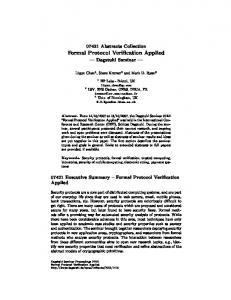
The general goal of the bootstrap protocol initiated after the election of the primary master is to ensure that the database is in a consistent state before the system enters its operational state. To reach this consistent state, the following points must be checked: – All expected data are stored on the storage nodes that are responsible of it. – All transactions (in its database meaning) have been completed. – All nodes have the same partition table and are aware of the identifiers (IDs) of the last transaction performed and of the last object updated. In Figure 15, the different phases of primary master and storage nodes are displayed along a time axis. This graph corresponds to the normal work of the protocol. An error occuring in one phase may cause the recall of preceding phases.
216
C. Choppy et al.
Primary
elected
Recovery
Storage connected to primary master
Veri�cation
Veri�cation
Service Initialisation
time Service
Fig. 15. Primary master and storage nodes phases in time
Each phase (e.g. verification, recovery) in the lifecycle of a node is characterised by a handler specifying how the different messages expected during this phase are handled. From the code perspective, a handler is a Python class containing one method per type of packet expected. This method is triggered upon the reception of such a packet. In the absence of the appropriate method, the packet is rejected and an exception raised. These handlers are called by the poll method that has been described in more details in Section 4. Right after its election the primary master first does some preliminary work: it announces itself, and checks the list of known storage nodes. Normally, during this period of time a storage node should connect to the primary master and set up the verification handler. It means that from the storage side a verification phase begins. Meanwhile, the primary master starts a recovery manager. After the recovery manager finishes its work, the primary master starts the verification manager, which verifies all the pending transactions on storage nodes. Verification phases of storage and primary nodes finish at the same time. Then the primary master sets up its service handler, and the storage node sets up an initialisation one, moving to an initialisation phase. When the initialisation phase is completed, the storage node goes to service state, performing replication (hatching on Figure 15) of data from time to time (a first time at the very beginning since some data might be missed while the storage node was down). To be in the operational state, a storage node must be connected to the primary master, have an up-to-date partition table, the last identifiers (last transaction ID and last object ID) and the list of available nodes (regardless of their type). All this is obtained during the first phases of the storage cycle. The cluster state reached is then sound since data is consistent across storage nodes before the cluster becomes operational. If an exception is caught while the system is operational, it may lead to restart the execution from one of the preliminary phases, according to the exception handled. For example, in case the primary master crashes, a new master node is elected and storage nodes must receive from this new primary master all the information listed above. 5.1
Model Architecture
The graphical conventions are the same as in Section 4.2. For instance, poll_ver (see Figure 16) is an abstract transition which is “implemented” by the net of Figure 7. Places from initial to operate in Figure 16 model the control flow of
Modelling and Formal Verification of the NEO Protocol
217
storage nodes. The model of the poll function introduced in the previous section has been reused during the modelling of the bootstrap protocol. Therefore, we only describe in this section the packet handlers of the bootstrap steps. Shared Places. Places network (described in Section 4.3), has_pt_ni_lid, LastOID and LastTID model important resources of the protocol and are shared by several modules. – Place has_pt_ni_lid allows to check when storage nodes can move from the verification phase to the operational mode. It always contains, for each storage node s, a single token �s, pt, ni, lid� such that pt = T iff s received the partition table; ni = T iff s received the list of nodes belonging to the cluster (i.e. the node information); and lid = T iff s received the last identifiers regarding the partition table. – Places LastOID and LastTID contain, for each (storage or master) node n, the last object (resp. transaction) identifier id the node is aware of. This information is modelled by a token �n, id� in the corresponding place. Global Level Storage Node Model. The model in Fig. 16 together with the declarations in Table 2 represent the functioning of a storage node from a global perspective. Every storage node starts its life cycle in place initial. It then listens to connections with some identification handler (transition start_listen puts a storage token into place listen_conn), and handles all the attempts of other nodes to connect. This is typically used during the replication phase, when some storage node has detected that it is out-of-date. It connects to another storage node that currently has the up-to-date copy of the required data. The primary master also starts listening to connections at some moment. From then on, other nodes can connect to it. Note that no node can connect to another one if the second one is not listening to connections. The next important step in the storage node life cycle is the connection to the primary master. Formally, it waits until place primary contains a token (in the current version of the model it means that the primary master has announced itself; later it should be modelled by exchange of messages) and a place listen_conn has the same token, meaning that the primary master has opened Table 2. Declarations for the nets in Figures 16–19 class SN is 0..10; MN is 1..3; MTYPE is [AskNI,AskPT,AskLID]; OP,PT,NI,LID,REP is [T,F]; PART is 1..20; PSTATE is [UP,OUT]; ID is 1..100; NSTATE is [RN,TD,DW,BR];
domain SNxOPER is �SN,OP�; SNxPTxNIxLID is �SN,PT,NI,LID�; NODE is [SN,MN]; NODExNODE is �NODE,NODE�; MESS is �NODE,NODE,MTYPE,INT�; SNxID is �SN,ID� SNxPART is �SN,PART� NODExNSTATE is �NODE,NSTATE� PARTxINT is �PART,INT�
218
C. Choppy et al. initial : SN
_
�s�
start listen �s� listening : SN
_ _
�s�
conn to pm
primary : MN network : MESS
�pm� verif : SN �pm�
,0 + ,0 + ,0
�pm, s, AskPT � �pm, s, AskNI � �pm, s, AskLID � init : SN
_
�s�
�s�
�s�
_
listen conn : NODE
�pm� �s, pm� �s� �s, T �
_ _ _
ask pt ni lid �s�
�s�
perf oper
live : NODExNODE
_
poll ver
operational : SNxOP
_
poll init
�s� �s, T, T, T �
_ _ _
has pt ni lid : SNxPTxNIxLID
�s� operate : SN
Fig. 16. Storage nodes global level
a listening connection. Transition conn_to_pm checks the presence of these two tokens via test-arcs, puts one token containing a pair of storage and primary nodes into place live, which means that henceforth the connection between these two nodes is established. A storage token is put into place verif, saying that the storage node has started its verification phase by setting up a verification handler on its primary master connection. The verification phase is supervised by the primary master, i.e. a storage node only receives messages and handles them (transition poll_ver) until one of the handlers changes the value of the variable operational to true. In the net, place operational contains as many tokens as there are storage nodes in the system. Each of these tokens consists of a storage node identifier and the current value of its internal variable operational. As soon as it becomes true, the storage node sends a message asking for the actual version of the partition table, the last identifiers and the node information to the network (transition ask_pt_ni_lid) and proceeds to the initialisation phase (place init). Similarly, the storage node stays in place init listening to incoming messages (transition poll_init) until it receives the partition table, the last IDs (last transaction identifiers) and the node information. Finally, a storage token arrives in place operate. Hence, the storage node has reached its operational state and starts providing service. If everything goes correctly, it remains in this state forever. If an operation failure occurs, the life cycle continues from connection to primary, but the current version of the model does not cope with errors yet.
Modelling and Formal Verification of the NEO Protocol
_
_
new sn : SN
�s� �p�
_
_
to add : PART add cell
dead : SN
partition table : SNxPART �s, p�
�s, p� �0, id�
_
pt id : SNxID
�0, id + 1� �s, nr + 1�
_ _
�s�
�0, id� �0, id + 1�
�s, nr�
219
�s, nr�
�p�
_
_
del cell to del : PART
�s, nr − 1�
number of repl : PARTxINT
Fig. 17. Model of the partition table
The Partition Table. The partition table is one of the key elements of the protocol implementation. It allows for making a correspondence between pieces of data and the storage nodes where they (or their copies) are saved. The overall data is divided into partitions. The number of partitions is defined by the system administrator before the cluster is started, according to physical parameters of the system such as the expected volume of data, the number of available storage nodes, and the degree of data safety (how many replicas should be saved). The number of partitions cannot be changed during the cluster life cycle. For each object, the number of partitions to which it belongs is defined by the simple formula: (Object Identifier) modulo (Number of Partitions). So, the partition number is equal to the remainder of the division of Object Identifier by the Number of Partitions. In the partition table, each row corresponds to one partition and contains the IDs of the storage nodes where the partition is located. Figure 17 represents the basic model of the partition table that contains two transitions: add_cell allowing to add a partition and del_cell allowing to delete a partition. The internal structure of the table is represented by two places: partition_table and number_of_repl. The first one contains pairs �storageID, partitionID� establishing a correspondence between partitions and storage nodes. If the protocol operates correctly, there should be no duplicates. Place number_of_repl contains exactly one token per partition that includes its ID and the number of tokens in the place partition_table corresponding to it. The other places model the input arguments for the functions add and delete, and are shared with other subnets. 5.2
Formal Modelling of the Verification Phase
Figure 18 presents the models handling messages, that are called when a storage node is in the verification phase. The goal of this phase is to check that all expected information persists and there is no pending transaction. The process of verification is managed by the primary master. All transitions have two common input places: pollStart (corresponding to a storage node that is handling a message) and network (corresponding to the message that is being handled). There
220
C. Choppy et al. network : MESS
pollStart : SNxMN �s, pm�
�s, pm, AskPT, 0�
�s, id�
handleAskP T
network : MESS
P T ID : SNxID
�s�
�pm, s, AnsPT, id�
pollEnd : SN
(a) “Ask partition table” network : MESS
pollStart : SNxMN �s, pm�
�s, pm, AskLID, 0� handleAskLID �pm, s, AnsLID, K(oid, tid)� network : MESS
�s�
�s, oid�
�s, tid�
LastOID : int LastT ID : int
pollEnd : SN
(b) “Ask last identifiers” network : MESS
pollStart : SNxMN
�s, pm, NotPCh, i� handleN otP Ch
�s, pm� �s, id�
_
pt id : SNxID
�s� �s, i� pollEnd : SN
(c) “Notify partition changes” network : MESS
pollStart : SNxMN
�s, pm, StartOp, 0� handleStartOp
�s, pm� �s, F�
operational : OP
�s� �s, T� pollEnd : SN
(d) “Start operation” Fig. 18. Verification phase handlers of storage nodes for different message types
is also one common output place pollEnd where a storage token is placed after handling a message. Handling ask messages (with ask in the name) finishes with a response that is put into place network, to notify it is sent: 1. handleAskPT (Ask Partition Table, Figure 18(a)) — Since it is not possible to model the complete partition table without facing the state space explosion problem, only the ID number of the table is sent. Thus the response from a
Modelling and Formal Verification of the NEO Protocol
221
storage node to a AskPT message is of type AnsPT with the current partition table ID as parameter. 2. handleAskLID (Ask Last IDs, Figure 18(b)) — When a storage node receives an AskLID message, the primary master requests the last transaction ID and last modified object ID. If any of these numbers is greater than the one currently known by the primary master, the latter saves those IDs obtained from the storage node and considers them as last. Hence, transition handleAskLID takes two tokens from places LastOID and LastTID respectively (corresponding to the storage node that is currently handling this message) and replies with an answer message to the network place of type AnsLID: receiver pm, sender s, information K(oid,tid) (where K is a one-to-one mapping from naturals to pairs of natural numbers). 3. handleNotPCh (Notify Partition Changes, Figure 18(c)) — This message is sent by the primary master in case the structure of the partition table is changed. This may happen for different reasons: some storage nodes crashed, new storage nodes are added or the distribution of the partitions is not uniform. This message actually contains all the rows of the table that have been changed, but for the modelling purposes only the partition table ID is sent. Hence transition handleNotPCh replaces a token corresponding to the current storage node in place pt_id with a new one with the ID just received. From then on, this storage node contains this partition table. 4. handleStartOp (Start Operation, Figure 18(d)) — This message is sent when the primary master considers the verification phase finished and allows to proceed to the next stage. Transition handleStartOp sets the value of the token in place operational to true. In the global level model, this activates transition ask_pt_ni_lid and storage nodes can move from place verif to init. 5.3
Formal Modelling of the Initialisation Phase
The goal of the initialisation phase (Figure 19) is that every node has the same partition table, and the IDs of last transaction and last modified object. The handlers for receiving last IDs and nodes information from the primary master are very simple. Storage nodes just save the values received in the appropriate places and change the corresponding boolean. Similar to the verification phase, all transitions have two common input places (pollStart and network) and one common output place pollEnd. 1. handleNotNI (Notify Node Information, Figure 19(a)) — The primary master uses NotNI messages to announce to the storage nodes their new status. If the new status of a storage node is DW (down), TD (temporarily down) or BR (broken), it closes its connection with the primary master and shuts down. Formally, transition handleNotNI replaces a token corresponding to current storage node from s_state with one corresponding to the new status (function NState(i) is a simple mapping of integer i to the colour domain of storage states). It also removes a token with current storage and primary
222
C. Choppy et al. network : MESS
pollStart : SNxMN
�pm, s, NotNI, i�
�s, pm�
handleN otN I [N State(i) = TD | DW | BR]
�s, N State(i)� �s, nst� �s�
_
s state : NODExNSTATE
�s, pm� live : NODExNODE
dead : SN
(a) “Notify node information” network : MESS �s, pm, AnsLID, i�
pollStart : SNxMN �s, pm�
handleAnsLID
�s, pt, ni, lid�
_ _ _
has pt ni lid : SNxPTxNIxLID
�s� �s, i� �s, pt, ni, T� LastOID : ID pollEnd : SN
(b) “Answer last identifiers” network : MESS
pollStart : SNxMN
�s, pm, AnsNI, 0�
�s, pm�
handleAnsN I
�s, pt, ni, lid�
_ _ _
has pt ni lid : SNxPTxNIxLID
�s� �s, pt, T, lid� pollEnd : SN
(c) “Answer node identification” network : MESS
pollStart : SNxMN
�s, pm, AnsPT, i�
�s, pm�
handleAnsP T
�x, pt, ni, lid� �x, T, ni, lid�
�s�
�x, id�
_ _ _
has pt ni lid : SNxPTxNIxLID
_
pt id : SNxID pollEnd : SN�x, i�
(d) “Answer partition table” Fig. 19. Initialisation phase handlers of storage nodes for different message types
master nodes from place live, signifying that the connection between them is down and adds the storage node to place dead. 2. handleAnsLID (Answer Last ID, Figure 19(b)) — The storage node saves its last object ID in its database (place LastOID) and changes the value of has_pt_ni_lid from false to true, meaning that it now knows last IDs. 3. handleAnsNI (Answer Node Information, Figure 19(c)) — Similar to the previous message, only the boolean value of has_pt_ni_lid is changed.
Modelling and Formal Verification of the NEO Protocol
223
4. handleAnsPT (Answer Partition Table, Figure 19(d)) — The corresponding boolean is also changed, and a token in pt_id is replaced with the one containing the new partition table ID received in the message. 5.4
Desired Properties
The engineers working on the NEO protocol provided us with more than 70 properties (related to the whole system and not only to the election and bootstrap phases) they would like to check on our models. These descriptions had first to be refined for several reasons: the terms used to express some properties had different meanings according to the context, several properties were poorly expressed and had to be refined, others were really trivial to check and only required a careful look at the implementation, . . . Therefore, the statements were rewritten and we (with the engineers of the NEO protocol) retained three main requirements, namely R4, R5 and R6, that concern the bootstrap protocol. R4 - The first requirement for the bootstrap phase states that all storage nodes eventually reach the operational mode. It actually implies that the following two conditions hold: – All storage nodes have reached the operational state in every terminal node. – The reachability graph is acyclic. R5 - According to this requirement, there is at least one storage node, for each partition, that will be responsible for storing that partition. R6 - Similarly, the third requirement, implying that any storage node will store at least one partition, can also be expressed as a reachability property. 5.5
Analysis Results
We analysed several configurations of our CPN model through simulation and then through state space analysis. Table 3 provides statistics on the reachability graphs of these various instances. Each configuration is defined by a number of storage nodes (column N), and a replication factor (column Repl.), i.e. the number of storage nodes a partition is kept on. For all configurations we analysed, the reachability graph is acyclic. Hence, the termination of the bootstrap protocol is guaranteed. Moreover, all terminal markings respect our three requirements R4, R5 and R6 presented in Section 5.4 and describe only acceptable termination states of the bootstrap protocol: Table 3. State space results for several configurations Configuration Markings Terminal Transitions N Repl. markings 1 1 537 9 905 2 1 22,952 106 57,059 2 2 76,590 106 217,897
224
C. Choppy et al.
– all storage nodes and the primary master have reached the operational state; – the database is consistent: a partition is owned by at least one storage node and no storage node is empty. Terminal markings only differ on the content of place network containing messages in communication channels. This could mean that some messages (those still present in the network in the termination states) are not required for the system to be operational since they are not consumed. Therefore, the protocol could possibly be optimised by avoiding some messages in specific situations. It is noteworthy that the state space grows considerably with the number of storage nodes. Actually, more than the number of nodes involved, the number of messages exchanged is the major bottleneck in our analysis. Indeed, each time a node invokes function poll it can treat numerous different packets received, hence generating a comparable number of transitions. We believe that the use of partial order reductions [7] could efficiently tackle this issue. Since in most cases the order in which incoming packets are treated is irrelevant, the use of this technique should naturally leverage this source of combinatorial explosion. To conclude this analysis section we will stress the fact that although we did not find any actual problem in the implementation, we plan to perform further model checking with larger configurations and other analysis tools, e.g. using partial order or symmetry based reductions [5].
6
Conclusion and Perspectives
In this paper, we have presented our work on the modelling and analysis of the first two (and essential) steps of the NEO system, a protocol developed to manage very large distributed databases. The correctness of these steps is vital since it implies a coherent system state and database consistency when clients start querying the database. Checking this correctness is also probably the most difficult point since, once the system is functioning, synchronisations ensuring data consistency seem simpler. Modelling is achieved using a reverseengineering approach from the code. It required to devise appropriate choices to work on relevant and useful levels of abstraction at different steps. To this end, we used several tools motivated by the different complexities of the objects to be modelled: namely Coloane, CPN-AMI, CPN tools and Helena. We also identified a lack in the modeling tools we used in that, besides CPN tools, they do not easily support the creation of nets modularly and hierarchically structured. This observation led us to define an XML-based composition language to ease our task. This is, to our best knowledge, the first attempt to define such a language. The outcome of this analysis was profitable to the system designers in several ways. First, we could discover several suspicious election scenarios that led them to make their code more robust. Second, our analysis confirmed that a connection loss between two masters is a severe fault from which the system will not recover in most situations. Last, we increased their confidence in the bootstrap protocol by checking several configurations in which all expected properties are verified.
Modelling and Formal Verification of the NEO Protocol
225
In the future, three extensions of the work presented here will be considered. First, we intend to take into account the storage nodes failure during bootstrap. Several mechanisms are implemented by the protocol to manage this kind of issue and it is worthwhile analysing them through model checking. Second, we plan to verify the considered properties when the number of storage nodes is not known in advance, and thus take into account the fact that the number of storage nodes can change dynamically during execution. Finally, we plan to use other analysis techniques, especially through Coloane which can interface with several verification tools such as Great-SPN [2] and Prod [17].
References 1. 2. 3. 4.
5. 6.
7. 8. 9.
10. 11.
12. 13. 14. 15.
16. 17.
The Coloane tool Homepage, https://coloane.lip6.fr/ The GreatSPN tool Homepage, http://www.di.unito.it/~greatspn The ZODB Homepage, http://wiki.zope.org/ZODB/FrontPage Bertrand, O., Calonne, A., Choppy, C., Hong, S., Klai, K., Kordon, F., Okuji, Y., Paviot-Adet, E., Petrucci, L., Smets, J.-P.: Verification of Large-Scale Distributed Database Systems in the NEOPPOD Project. In: PNSE 2009, pp. 315–317 (2009) Chiola, G., Dutheillet, C., Franceschinis, G., Haddad, S.: A Symbolic Reachability Graph for Coloured Petri Nets. TCS 176(1-2), 39–65 (1997) Choppy, C., Dedova, A., Evangelista, S., Hong, S., Klai, K., Petrucci, L.: The NEO Protocol for Large-Scale Distributed Database Systems: Modelling and Initial Verification. In: Lilius, J., Penczek, W. (eds.) PETRI NETS 2010. LNCS, vol. 6128, pp. 145–164. Springer, Heidelberg (2010) Clarke, E.M., Grumberg, O., Minea, M., Peled, D.: State Space Reduction Using Partial Order Techniques. STTT 2(3), 279–287 (1999) ERP5. Central Bank Implements Open Source ERP5 in Eight Countries after Proprietary System Failed, http://www.erp5.com/news-central.bank Evangelista, S.: High Level Petri Nets Analysis with Helena. In: Ciardo, G., Darondeau, P. (eds.) ICATPN 2005. LNCS, vol. 3536, pp. 455–464. Springer, Heidelberg (2005) Haddad, S., Pradat-Peyre, J.-F.: New Efficient Petri Nets Reductions for Parallel Programs Verification. Parallel Processing Letters 1, 16 (2006) Hamez, A., Hillah, L., Kordon, F., Linard, A., Paviot-Adet, E., Renault, X., Thierry-Mieg, Y.: New Features in CPN-AMI 3: Focusing on the Analysis of Complex Distributed Systems. In: ACSD 2006, pp. 273–275. IEEE Computer Society (2006), http://move.lip6.fr/software/CPNAMI/ Huber, P., Jensen, K., Shapiro, R.M.: Hierarchies in Coloured Petri Nets. In: Rozenberg, G. (ed.) APN 1990. LNCS, vol. 483, pp. 313–341. Springer, Heidelberg (1991) Jensen, K., Kristensen, L.M.: Coloured Petri Nets, Modelling and Validation of Concurrent Systems. Springer Verlag Monograph (2009) Jensen, K., Kristensen, L.M., Wells, L.: Coloured Petri Nets and CPN Tools for Modelling and Validation of Concurrent Systems. STTT 9(3-4), 213–254 (2007) Kordon, F., Linard, A., Paviot-Adet, E.: Optimized Colored Nets Unfolding. In: Najm, E., Pradat-Peyre, J.-F., Donzeau-Gouge, V.V. (eds.) FORTE 2006. LNCS, vol. 4229, pp. 339–355. Springer, Heidelberg (2006) University of Hamburg. The Petri Nets Tool Database, http://www.informatik.uni-hamburg.de/TGI/PetriNets/tools/db.html Varpaaniemi, K., Heljanko, K., Lilius, J.: Prod 3.2: An Advanced Tool for Efficient Reachability Analysis. In: Grumberg, O. (ed.) CAV 1997. LNCS, vol. 1254, pp. 472–475. Springer, Heidelberg (1997)