International Review on
Modelling and Simulations (IREMOS)
PART
B
Contents
Copyright © 2013 Praise Worthy Prize S.r.l. - All rights reserved
(continued from Part A) The Attenuation Calculation of the Energy Signal of a Gaussian Pulse Propagating in the Human Body to Detect the Heart Beat by Moez Ketata, Alain Loussert, Mohamed Dhieb, Mongi Lahiani, Hamadi Ghariani
937
Design and Implementation of Dynamic Voltage Restorer for Harmonic Compensation by C. Gopinath, R. Ramesh
946
Broadband Impedance Matching Techniques for Microwave Amplifiers [10-12] GHz by M. Lahsaini, L. Zenkouar, S. Bri
953
Investigation of Electromagnetic Effect of Lightning on Indoor Motion Detectors and Their Cables Using FEM by A. S. Cabuk, O. Kalenderli
962
Efficient Power Allocation in Turbo Decoded OFDM Systems Using Logarithmic Maximum A-Posteriori Algorithm and Soft Output Viterbi Algorithm Under Various Fading Environments by Sabitha Gauni, R. Kumar, G. Sankardhayalan
967
Simulation Studies of Follow Current Struck by 10/350µs Impulse Current by Xiaoming Ren, Qin Zhou
976
Biomass and Solar Integration in Low Enthalpy Geothermal Plants by A. Amoresano, P. De Sio, G. Langella, S. Meo
981
Effect of the Backlight Angle on the Aero-Acoustics of the C-Pillar by Sajjad Beigmoradi, Asghar Ramezani
988
Modeling and Control of Combined Cycle Gas Turbines Using Rowen’s and Vournas’s Models by Mohamed M. Ismail, M. A. Moustafa Hassan
994
State Estimation and Sensor Bias Detection Using Adaptive Linear Kalman Filter by M. Manimozhi, Gutha Snigdha, Nagalakshmi S., R. Saravana Kumar
1005
Thermal Buckling of Functionally Graded Material Plates with Actuator-Actuator Piezoelectric Layers Based on Different Plates Theories by R. Shahveh, J. Mohammadi, A. Kordi Broujeni, Sh. Yousefzadeh
1011
Theoretical and Experimental Estimation of the Hysteretic Component of Friction for a Visco-Elastic Material Sliding on a Rigid Rough Surface by Flavio Farroni, Riccardo Russo, Francesco Timpone
1023
Nonlinear Discrete-Time Gain-Scheduling Control for Affine Nonlinear Polynomial Systems by S. Charfeddine, H. Jerbi, L. Sbita
1031
International Review on Modelling and Simulations (I.RE.MO.S.), Vol. 6, N. 3 ISSN 1974-9821 June 2013
The Attenuation Calculation of the Energy Signal of a Gaussian Pulse Propagating in the Human Body to Detect the Heart Beat Moez Ketata1, 2, Alain Loussert2, Mohamed Dhieb1, Mongi Lahiani1, Hamadi Ghariani1 Abstract – This work is part of a project whose goal is the study of abnormal attenuation and distortion of the Ultra Wide Band signal "UWB" during its propagation in the human body to detect heart beats. This paper describes a method to determine the attenuation of the signal energy through the region of the body in the heart area; this region is modelled like the superposition of four semi-infinite layers, each characterized by its thickness, conductivity and dielectric constant. This method consists in seeking attenuation in biological samples of the same type as the layers forming the human body. Hence we deduce the overall attenuation in the total model. A comparison is made with other work that exists in the literature to show the robustness of our method. We adopt the FDTD method "Finite Difference Time Domain" to simulate the propagation of a Gaussian pulse whose pulse width varies from 1 to 10 GHz in these biological media. These samples should not be too thin not to have any energy fluctuation area along the sample, or too large not to risk dampening the signal especially for very short pulses. For this, we select 2.5 cm wide samples located 1 cm from the source (antenna). Copyright © 2013 Praise Worthy Prize S.r.l. - All rights reserved.
Keywords: Attenuation, Finite Difference Time Domain (FDTD), Ultra Wide Band (UWB) Wave
r Sav
Average reflected power density [W/m²]
[V/m]
i Sav
[A/m] [C/m2]
Tb
The average incident power density. Coefficients of transmission from layer 1 to layer 2. The celerity of light
Nomenclature E x
Electric field intensity vector (normalized Gaussian units) H Magnetic field intensity vector Electric flux density vector Dx (normalized Gaussian units) Δz Cell size Δt Time step Attenuation of the transmitted Attr energy by the signal from the antenna in position k Attenuation of the reflected Atref energy signal with respect to the antenna position k The energy of the transmitted Es _ tr signal in position k The energy of the reflected Es _ tr signal in position k The energy of the incident Es _ antenna signal at the source Maximum amplitude of the Emax_ tr k transmitted electric field in position k The maximum amplitude of the Emax_ ref k reflected electric field position k Emax_ antenna k Maximum amplitude of the incident electric field at the source antenna t Average transmitted power Sav density
C
[W/m²] [m/s]
[m] [s] [dB]
Greek notations Intrinsic impedance in layer 1 1
[Ω]
Intrinsic impedance in layer 2
[Ω]
[dB]
2 1 2
[j]
σ
[j]
εr
Conductivity of the medium Relative Permittivity Angular frequency Free space permeability Free space permittivity
ω μ ε
[j]
0
0
[V/m]
Attenuation coefficient of layer 1
[m-1]
Attenuation coefficient of layer 2
[m-1]
Attenuation coefficient of layer
[m-1] [S/m] [F/m] [rad/s] [H/m]
[F/m]
Subscripts k Distance counter n Time counter Coefficients of transmission from layer 1 to Tb layer 2 b Coefficients of reflection from layer 1 to layer2 * r Permittivity dependant complex relative dielectric constant
[V/m] [V/m]
[W/m²]
Manuscript received and revised May 2013, accepted June 2013
Copyright © 2013 Praise Worthy Prize S.r.l. - All rights reserved
937
Moez Ketata, Alain Loussert, Mohamed Dhieb, Mongi Lahiani, Hamadi Ghariani
I.
Introduction
II.
Research on biomedical applications of UWB radar is designed to identify a feasible new device, made feasible thanks to the design and development of these devices in clinical tests of the obtained systems [1], [2]. This work is part of the thesis work whose aim is the modelling of the propagation medium of radars pulse in their displacement to the heart to detect heartbeats. In previous work, established by Enrico Staderini and Bilich [1], [3], the estimation of the attenuation was based on experimental trials [4], [5] or mathematical formulas [6]. In this one, we try to find a method here that is as close as possible to reality and that explains the ambiguities found in the two previous works. The method is to seek the attenuation of a pulse during its propagation to the heart from the attenuation in biological samples from the transmission media corresponding to the human body based on the FDTD method. The FDTD (Finite Difference Time Domain) [7] is a technology used to solve Maxwell's equations. This method is used to record the amplitude of the calculated electric field in each point of space and to deduce the attenuation in biological samples. Then, we carry out an interpolation of the first order far from the interfaces in the linear region. Then to deduce the attenuation in the human body, in each layer, we define a function of the linear attenuation whose coefficient is the one that has been determined above. At the interfaces, we reduce by 10 dB the coefficient due to intrinsic impedances of the two layers. The paper is organized as follows: in Section 2, we develop the model of the propagation media. And before defining the attenuation of the signal energy in Section 4, Section 3 describes the resolution of Maxwell's equations by the FDTD method. Section 5 discusses models existing in the literature including the models of Staderini and Bilich by making a comparison between these two models. Finally, Section 6 describes the method that was proposed to seek attenuation of the energy signal. We also make a comparison with the two previous models and summarize the results.
Propagation Medium Model
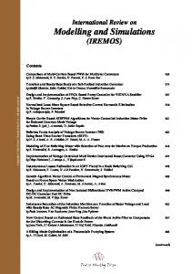
From the cross-sectional taken from [13] and a study of anatomical design, we found that we can model the propagation media, "environments where a wave propagates to detect heart beats" like an assembly of four layers (Fig. 1) [1], [3], [4], [8] laminated one after the other, each characterized by its thickness (Table I) [1], [3], [8], [11], the conductivity (Table II) and its dielectric constant (Table III) [5], [11].
Fig. 1. Simplified model of the propagation medium of a Gaussian pulse in his propagation to the heart TABLE I THE THICKNESSES OF THE LAYERS FORMING THE BIOLOGICAL BODY [1] Type of layer Thicknesses [cm] Fat 0.96 Muscle 1.35 Cartilage 1.16 Lung 0.578
The conductivity and the dielectric constant are dependent on the frequency corresponding to the width pulse to be sent for the pulse-echo model and the propagation frequency, if the wave is continuous in time. The following tables (Tables II and III), give an idea of the variation of these parameters as a function of frequency for the different layers [3].
TABLE II CONDUCTIVITY VALUES FOR LAYERS OF THE HUMAN BODY[11] Frequency (GHz) Type of layer Fat Muscles Cartilage Lung Heart
1
2
3
4
5
6
7
8
9
10
0.04 0.92 0.89 0.87 1.28
0.086 1.454 1.423 1.395 1.96
0.13 2.142 2.205 2.085 2.28
0.1829 3.016 3.110 2.943 2.305
0.2422 4.045 4.085 3.941 3.876
0.307 6.461 6.108 6.244 5.13
0.443 7.798 7.11 7.50 6.19
0514 9.192 8.083 8.796 7.87
0.514 9.192 9.083 8.796 8.77
0.585 10.626 9.023 10.112 10.35
TABLE III DIELECTRIC CONSTANT VALUES FOR THE FOUR LAYERS OF THE HUMAN BODY[11] Frequency (GHz) Type of layer
1
2
3
4
5
6
7
8
9
10
Fat Muscles Cartilage Lung Heart
5.447 53.29 42.317 51.10 59.28
5.328 52.08 39.75 49.5 54.59
5.22 50.821 37.605 47.604 52.8604
5.125 49.54 35.57 46.22 51.35
5.029 48.21 33.62 44.859 44.859
4.937 46.86 31.79 43.472 43.472
4.848 45.49 30.07 42.077 48.177
4.762 45.49 28.47 40.685 45.785
4.680 44.12 26.99 39.306 44.806
4.602 42.764 25.63 37.951 42.24
Copyright © 2013 Praise Worthy Prize S.r.l. - All rights reserved
International Review on Modelling and Simulations, Vol. 6, N. 3
938
Moez Ketata, Alain Loussert, Mohamed Dhieb, Mongi Lahiani, Hamadi Ghariani
We adopted for the dielectric constant the following formula which describes a lossy dielectric medium: [7].
*r r j
0
(1)
III. Solving Maxwell's equations by the FDTD method In adopting this model which describes the dielectric medium, we solve Maxwell's equations by the FDTD method [7], [8], describing the propagation of a Gaussian pulse by: 1 + = 2 −
∆
( + 1) −
∆
Fig. 2. Incident, transmitted and reflected waves
1 + + 2 ( )
( )= −
( )+ 1 + − 2
In a first time, we seek in the literature some work using the models we have described for the propagation media. But, we must define the attenuation of the energy signal. At first, we can set the attenuation of transmitted or reflected energy signal with regard to the source (antenna) [10] (Fig. 2):
(2)
∆ ∆
−
1 2
(3)
=
=
( ) = 10
( ) = 10
(
−
(5)
)
(6) = 10
=
+
_
_
_
_
_
_
( )
(10)
( )
(11)
_
( )= _ ( )
+
(12)
+
(13)
(7) −10
IV.
(9)
But due to the discontinuity at the interfaces, we must first of all, find the attenuation of each layer from the signals found by the FDTD method. Then, we deduce the attenuation with regard to the antenna by adding the attenuation at the interface, in each layer, if we consider that the source sends unitary pulses:
(4)
∆
_
_
1 +
( )
In the review [10], it was shown that the energy of the signal at a position k, is proportional to the amplitude of the electromagnetic field, so we can transform equations (8), (9) as follows:
1
∆
(8)
_
and : show that the distribution is Gaussian [8]. In these two equations, the time specified by the exponents "n" actually means a time t = n∙Δt and the distance is shown in brackets, "k" actually refers to the distance z = k. Δz with "Δt" the time step and "Δz" the spatial step. [7], [9] The present value " " of electrical component can be calculated from the present values of " " and the previous value of E. It will advantageous to define a new parameter for simulation: ∆
_
( ) = 10
D(ω) = ε 0 εr*(ω) E(ω)
+
( )
_
where:
=
_
( ) = 10
_
Calculation of Attenuation
In this section, we want to determine the profile of the attenuation in the human body for a width pulse varying from 3 GHz to 10 GHz. (Ultra Wide Band UWB) to control the FDTD simulation in dielectric media.
= 10
_
( )= _ ( ) é
−10
Copyright © 2013 Praise Worthy Prize S.r.l. - All rights reserved
__ é
International Review on Modelling and Simulations, Vol. 6, N. 3
939
Moez Ketata, Alain Loussert, Mohamed Dhieb, Mongi Lahiani, Hamadi Ghariani
V.
From these expressions listed above and the field parameters extracted from the articles of Gabriel [5], Carlos Bilich validated his model by calculating first parameters of the 1.5 GHz model (Table V and Fig. 4). He found a difference of 2.8 dB. After validating the procedure at 1.5 GHz, he continued the calculation at 4 GHz, which is the frequency chosen in the proposal. Table VI shows the values and parameters at 4 GHz (Fig. 5). In the next section, we will compare the two models trying to show possible errors. Although the Enrico Staderini’s model, seems exact from an physical point of view, since it is based on experimental tests, it is intrinsically flawed. Indeed, on the one hand it uses a continuous narrow band wave at 1.5 GHz [4] to measure the dielectric properties and not the pulse-echo model. On the other hand, he did not specify the attenuation gaps at each interface and the reflected wave (calculation of the reflection coefficient). However, Carlos Bilich attempted to validate a first model of attenuation at 1.5 GHz obtained by C. Balanis’ mathematical relations [5], by comparing it to Enrico Staderini’s model based on experimental tests. Then, it has established its attenuation model at 4 GHz. But, although he managed to obtain attenuation at the receiving antenna very close to that depicted in the model of Enrico Staderini (the difference is only around 2.80 dB "-37.8 vs - 35 dB "), he did not explain the terms of intrinsic impedances appearing in the mathematical model. On the other hand, if we compare Fig. 3 (attenuation model of Staderini) with Fig. 4 (attenuation model obtained from mathematical equations), we see that Bilich did not specify the discontinuities of energy attenuation especially at the airfat and fat-muscle interfaces. And 4GHz model is almost underestimated. He considers them as continuity areas.
Staderini and Bilich’s Model
Enrico Staderini from the University of Rome ''Tor Vergata"[1] worked on the same model of the propagation layers and proposed an attenuation model at 1.5GHz based on experimental works at the University Rome, from the data obtained from the Visible Human Project [12] and Gabriel’s measures of dielectric properties of tissues [5]. The data allow the calculation of time echoes of the linear attenuation and transmission and reflection coefficients [1], [3], [11]. See tab1 and Fig. 3. Similarly, Carlos Bilich tried in his work [3] to calculate the attenuation of an electromagnetic wave propagating in the human body at 4 GHz. Note that in his technical report entitled "UWB radars for Biomedical Sensing: Attenuation Model for Wave Propagation in the Body at 4 GHz", he validate his model based on mathematical equations derived from C. Balanis’ work, in his book "Advanced Engineering Electromagnetic. John Wiley & Sons"[6] by validating mathematical model with experimental work of Enrico Staderini’s model. Then, he established his model at 4 GHz. According to Balanis, power densities depend on the transmission and reflection coefficients at the interface, layer intrinsic impedance environments and the layer attenuation coefficient. The transmitted average power density can be written as follows: |
= =|
|
Type of layer Fat Muscles Thorax Lung Heart
Media Air Fat Muscle Cartilage Lung Heart
Media -Air Fat Muscle Cartilage Lung Heart
W
|
σ 0.00 0.09 1.75 1.00 0.55 1.50
W
m
m
(14) (15)
TABLE IV ANATOMY AND ELECTROMAGNETIC PROPERTIES OF TISSUE LAYERS IN THE THORAX [1] Impedance Attenuation Speed (ohm) (m-1) (ms-1)* 108 376.5 0.00 2.998 112.6 8.96 0.8958 49.9 31.67 0.3978 58.16 31. 93 0.4628 52.86 29.62 0.4206
Thickness (cm) 1 0.96 1.35 1.16 0.578
TABLE IV ANATOMY AND ELECTROMAGNETIC PROPERTIES OF TISSUE LAYERS IN THE THORAX [1] εr α η Гb Tb η1/η2*[Tb]2 Tb(dB) 1.00 0.00 376 5.50 6.83 160 -0.4 0.6 0.84 -2.23 55 44.4 50.8 -0.52 0.48 0.73 -3.18 40 29.8 59.6 0.08 1.08 0.99 0.33 20 23.2 84.2 0.17 1.17 0.97 0.69 60 36.5 48.6 -0.27 0.73 0.93 -1.35
TABLE VI COEFFICIENTS OF THE FIELD PARAMETERS, ATTENUATION, REFLECTION AND TRANSMISSION AT 4 GHZ σ εr α η Гb Tb η1/η2*[Tb]2 Tb(dB) 0.00 1.00 0.00 376.73 0.25 5.50 20.0 160.64 -0.4 0.6 0.84 -2.23 3.5 50 93.2 53.28 -0.5 0.5 0.75 -3.03 3.00 35 95 63.68 0.09 1.1 0.99 0.37 5.50 20 63.2 84.24 0.14 1.1 0.98 0.69 4.00 55 101 50.8 -0.25 0.7 0.94 -1.24
Copyright © 2013 Praise Worthy Prize S.r.l. - All rights reserved
η1/η2*[Tb]2(dB) -0.77 -1.37 -0.03 -0.13 -0.32
η1/η2*[Tb]2(dB) -0.77 -1.26 -0.03 -0.0 -0.27
International Review on Modelling and Simulations, Vol. 6, N. 3
940
Moez Ketata, Alain Loussert, Mohamed Dhieb, Mongi Lahiani, Hamadi Ghariani
This results in a space-time matrix, whose variation of the columns indicates the spatial distribution of the electric field at a given time and the diversity of the lines indicate the time variation of the electric field at a position z of the space. From this matrix, we seek the energy signal at each position. This energy, as shown in [10] is proportional to the square of the maximum amplitude, in each position. Finally, we deduce the transmitted and reflected attenuation’s with regard to the antenna from Eqs. (8) and (9). Bilich FDTD method
0
-5
A tte n u a tio n (d B )
-10
Fig. 3. Attenuation model in human tissue proposed by Staderini at 1.5 GHz
-15
-20
-25
Air
Muscle
Fat
Cartilage
Lung
Heart
-30
-35
0
0.01
0.02
0.03
0.04
0.05
0.06
Z(m)
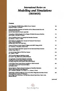
Fig. 6. Transmitted attenuation model obtained from the FDTD method (in red) and attenuation model of Bilich (green) at 4 GHz
Fig. 6 shows the transmitted attenuation obtained from the FDTD method and that obtained by the Bilich’s model at 4 GHz. We note the existing disturbances at interfaces air-fat and fat-muscle. These disturbances are due to the resolution of the spatial-temporal step of the FDTD method at interfaces. So we need to modify them, but it requires a very long simulation time with a non-constant spatial step. We cannot compare this model with the other methods, so it is important to find another way to seek attenuation in the UWB domain.
Fig. 4. Attenuation model in human tissue at 1.5 GHz obtained from Table V
VI.2. The Model Adopted to Calculate the Attenuation To seek the attenuation of the energy signal in the human body and for a frequency (pulse width) which varies in the Ultra-Wideband domain (1-10 GHz), we do as follows: first we seek the attenuation in a single layer which forms the body. Then, we try to deduce the attenuation in the human body from these curves. The following Fig. 7 shows the model that we will adopt for the simulation by the FDTD method. At each step, we modify the biological sample and seek its attenuation in the Ultra Wideband domain. The following figures show the different attenuation in biological Samples. Then we seek a linear interpolation outside the disturbed area of the signal as shown in the following figure (Fig. 9). This figure provides a layer of biological tissue forming the human body (model: Figure 1) for a fixed frequency.
Fig. 5. Attenuation model in human tissue at 4 GHz obtained from Table VI
VI.
Method Adopted to Calculate the -Attenuation
VI.1. Attenuation for Laminated Layers of the Model To check the attenuation of the signal energy in the human body, we first use the FDTD code for the propagation of a Gaussian pulse and constantly register the evolution of the electric field in space.
Copyright © 2013 Praise Worthy Prize S.r.l. - All rights reserved
International Review on Modelling and Simulations, Vol. 6, N. 3
941
Moez Ketata, Alain Loussert, Mohamed Dhieb, Mongi Lahiani, Hamadi Ghariani
Fig. 7. The model adopted for the simulation by the FDTD method
Fig. 8. Attenuation in biological sample
We do, for the reflected attenuation, the same thing except that we take the opposite of the coefficient "a" into account. The following curve (Fig. 10) compares the profile of the attenuation of the energy signal found by this method (explained above) and Carlos Bilich’s model at 4 GHz.
0
-4
-6
10
-8
0
Air
-10
Air
-10
-12
0.05
0.055
0.06
0.065
0.07
0.075
0.08
0.085
Bilich simulation
BioIogic Tissue
Attenuation (dB)
Attenuation(dB)
-2
0.09
0.095
-20 -30
FAT
Air
Muscles
Cartilage
Lung
Heart
-40
0.1 -50
Z(m)
-60
Fig. 9. Attenuation in biological samples
-70
We interpolate the attenuation in the dielectric field, then for each coefficient we carry out a second order interpolation Eq. (16): ( , )= ( )∙ + ( )
0
0.01
0.02
0.03 Z (m)
0.04
0.05
0.06
Fig. 10. The model validation Carlos BILICH to 4GHz
But comparing relations (Eqs. (12) and (13)) with the model on which the Bilich’s model is based, (Eqs. (14) and (15)) changes the settings as follows:
(16)
To show continuity at interfaces, we return to our model of superposed layers and in each layer, a specific linear attenuation function was defined. The equation is defined in such a way that ensures continuity at the interfaces (Eq. 16) and we reduced of 20 dB the reflection coefficient at lung-heart interface.
( )
( ) = 10 = 10
Copyright © 2013 Praise Worthy Prize S.r.l. - All rights reserved
( )
= (17)
_
International Review on Modelling and Simulations, Vol. 6, N. 3
942
Moez Ketata, Alain Loussert, Mohamed Dhieb, Mongi Lahiani, Hamadi Ghariani
_
= (
(18)
)
This comes from the layer parameters that differ from one model to another. But the error is located at interfaces, especially for the Air-Fat and Fat-Muscle where Staderini did not specify the attenuation gaps at interfaces, whereas Bilich almost considers them as continually areas. Despite the error of nearly 7 dB on the receiving antenna versus Staderini and Bilich’s models, our model is closer to the mathematical model (Balanis, C. [6]). The following figure (Fig. 13) compares the attenuation at 4 GHz for Bilich’s model and the model obtained by the proposed method. The same remarks reported above are still valid. This shows that Bilich has validated only the attenuation coefficient in the mathematical model (Fig. 13).
By returning to Eq. (17) and identifying with these two equations, we can write this form: ( )
( ) = 10 _
= 10
_
_
(|
= 10
( )
= (19)
=
_
) + 10
|
This equation shows that if we cut the ratio between the two environments impedances at the interfaces of 10 dB, which BILCH was not to find its attenuation model to 4 GHz. We therefore propose the following corrections: Correction proposed: We define in each layer an linear attenuation function We reduce the ratio intrinsic impedance of two environments at each interface of 10 dB. We cut reflection coefficient at interface lung-heart of 20dB. We take the opposite of the coefficient "a" for reflected attenuation. We finally obtained this following set of curves (Fig. 11), for frequency corresponding to the pulse width ranging from 1 to 10 GHz.
10 Modèle Bilich à 4GHz 0 Modèle obtenu par la méthode proposée
Atténuation(dB)
-10 -20 -30
FAT
Air
Muscles
Cartilage
Lung
Heart
-40 -50 -60 -70 -80
0
0.01
0.02
0.03
0.04
0.05
0.06
Z(m)
Fig. 13. Comparison to 4 GHz with the model of Bilich
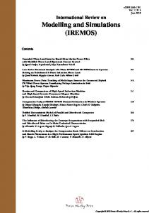
On the other hand, when, the frequency increases, the attenuation difference of the reflected signal at the reception between the two models decreases. Indeed, up to 1.5 GHz the difference between the two models is about 5 dB, but it is only about 3 dB at 4 GHz. Similarly, if we look at the percentages, this difference is approximately 11.11% at 1.5 GHz, and decreased to 7.15% at 4 GHz. The following table shows the difference between our model and the model that neglects these attenuation gaps at the interfaces. 14
Fig. 11. Set of curve obtained by the adopted method, for frequency range from 1 to 10 GHz
12
After the mathematical verification, we compare our model with that of Staderini Bilich at 1.5 GHz, then at 4 GHz on the following figures. We note from these curves (figure 12), that the shapes of the three curves are almost parallel with a slight deviation to the Staderini’s model, especially in the muscle layer.
Distance(%)
10
8
6
area n°1
area n°2
area n°3
4
2 0 10
1
10
f(GHz) 0 Bilich
Fig. 14. Difference of reflected attenuation at the receiving antenna between the discontinuity model and the models that neglect these attenuation gaps at the interfaces
Sterdeni
-5
Méthode proposée
Atenuation(dB)
-10
-15
Cartilage
Muscles
FAT
Air
Heart
Lung
-20
The results in this table are more explicit in Fig. 14. Figure 14 shows that there are three difference areas which are quasi-linear in frequency. The first area for a frequency between 1 and 3GHz, where the difference can be considered as large (between 9.09 and 12.5 %) and 1.11 % for the Staderini’s model, so the Bilich approximation in this area seems a bit exaggerated.
-25
-30
-35
-40
-45
0
0.01
0.02
0.03
0.04
0.05
0.06
Z(m)
Fig. 12. Comparison with Staderini and Bilich’s models of 1.5GHz
Copyright © 2013 Praise Worthy Prize S.r.l. - All rights reserved
International Review on Modelling and Simulations, Vol. 6, N. 3
943
Moez Ketata, Alain Loussert, Mohamed Dhieb, Mongi Lahiani, Hamadi Ghariani
TABLE VII DIFFERENCE OF REFLECTED ATTENUATION AT THE RECEIVING ANTENNA BETWEEN THE DISCONTINUITY MODEL AND THE MODELS THAT NEGLECT THESE ATTENUATION GAPS AT THE INTERFACES Frequency (GHz) 1 2 3 4 5 6 7 8 9 10 Distance (%) 12.5 10.20 9.09 7.15 5.88 4.55 3.85 3.33 2.86 2.56
A second area for a frequency band between 3 and 6 GHz where the difference is medium (between 4.55 and 9.09 %). This band coincides with the lower band of the Ultra Wide Band. At 4 GHz, the difference is 7.15 % and we can accept this approximation, if we allow deviations less than 10 %. A third zone for a frequency band between 6 and 10 GHz where the difference is less than 5%.
VII.
[10]
[11]
[12]
Conclusion
[13]
In this work, we have tried to clarify the problematic points that exist in the Bilich and Staderini’s models especially at the interface between two layers. We propose a method to seek the attenuation based on the FDTD method. This method give an attenuation model closer to the Balanis formula than the Bilich model, although the latter has established a model closer to Staderini’s one whose based on experimental tests. However, it should be noted that these attenuation gaps can be neglected in the Ultra Wide Band domain (3 to 10 GHz), if we allow relative differences between our proposed model and those whose consider interfaces like continuity areas, lower than 10 %. As a perspective, we will try to approximate the attenuation curve for the model of stratified layers with the obtained one by our proposed method in optimizing the FDTD code.
Authors’ information 1
LETI: Laboratoire. Electronique & Technologie De L'information, Route Soukra, km 3.5, B.P. 3038, Sfax, Tunisia. E-mails:
[email protected] [email protected] [email protected] [email protected] 2
ISEN Brest, L@bIsen, équipe Instrumentation Acoustique, 20 rue cuirassé Bretagne, C.S. 42807, 29228 Brest Cedex 2, France E-mail:
[email protected]. Moez Ketata was born in Sfax, Tunisia, on August 1977. He received the Electrical Engineering Degree from the“National Engineering School of Sfax -Tunisia” in 2004, the “MASTER” degree on electronics in 2007. He is currently working toward a “Doctorate on Electrical engineering” at the same university. Since 2007, he has worked as contractual assistant at the Faculty of Science of Gafsa. Also he is member in the“LETI” Laboratory ENIS Sfax. His main research interests are the techniques Radar for measurement of the physiological parameters of the human body.
References [1]
[2]
[3] [4]
[5]
[6] [7]
[8] [9]
method, IEEE Press Series on RF and Microwave Technology, Roger D, Pollard and Richard Booton, Series Editors, 2000. Dennis M. S.; Jacek, N. A Z-Transform Matrix Formulation for a Tensor FDTD Method, Antennas and Propagation Society International Symposium, 2007 1-4244-0878-4/07 Mur, G. Absorbing boundary conditions for the finite-difference approximation of time domain electromagnetic field equations, IEEE Trans. Electromagen. 1981, 23, 377-384 Chaoui. M, Ketata. M, Lahiani. M, Ghariani. H,. FDTD Simulation Method Using Double Signals for Electromagnetic Field: Determination of the Tissue Biological Characteristics, International Review on Computers and Software (I.RE.CO.S.), 2011, 6,. 6 Dielectric Properties of Body Tissues,.http://niremf.ifac.cnr.it/tissprop/htmlclie/htmlclie.htm (acced18/12/2012)
D. Gorinevsky, S. Boyd, and G. Stein, Design of Low-Bandwidth Spatially Distributed Feedback, IEEE Transactions on Automatic Control, Vol. 53(Issue 1):257-272, February 2008. Lazaro A., Girbau D., and Villarino R., "Analysis of vital signs monitoring using an IR-UWB radar, Progress In Electromagnetics Research, Vol. 100, 265-284, 2010. Staderini, M. UWB Radars in Medicine. IEE AESS Systems Magazine 2000, 1, 1-10. Thiel, F.; Hein, M.. Schwarz, U.; Sachs, J.; Seifert, F. Combining magnetic resonance imaging and ultra wide band radar: A new concept for multimodal biomedical imaging REVIEW OF SCIENTIFIC INSTRUMENTS, 2009, 80, 014302 Bilich, C. G. UWB Radars for Bio-Medical Sensing: Attenuation Model for Wave Propagation in the Body at 4 GHz. Informatica e Telecomunicazioni, Technical Report DIT-06-051University of Trento. Chang, Y.J, The NPAC Visible Human. Viewer, Syracuse University, NY. Gabriel, C. Compilation of the Dielectric Properties of Body Tissues at RF and Microwave Frequencies, Physics Department, King’s College London, London WC2R2LS, UK; Armstrong Laboratory (AFMC), Occupational and Environmental Health Directorate, Radiofrequency Radiation Division. Report: AOETR- 1996-0037. Balanis, C. Advanced Engineering Electromagnetics. John Wiley & Sons; USA, 1989; ch. 5. Dennis M. Sullivan. Electromagnetic simulation using the FDTD
Alain Loussert Head of Acoustic Laboratory "Acoustique et instrumentation" ISEN Since 2001 , Head of "Instrumentation" Laboratory (Underwater Acoustics) IEEE Senior Member. In charge of CoDesign Centre, In charge of Internship and Companies Relations Professor in Signal Processing. I did my thesis under the direction of Professor Jacques DELUSTRAC at the University of Toulon and Var (UTV), she received a fellowship from the DGA from February 1991 to June 1994. My thesis focused on the optimization of new concepts of reflector antennas for offering very low frequencies in the water. During my first year of study, I had the opportunity to turn to education and experience was also rewarding. Then I started my career in the industry where I continued the design of transducers for sonar and several companies working directly with the DGA and the French Navy.After working for several years in the industry, I wanted to give a new direction to my career and to turn both to the teaching and research in candidate in a general high school in electronic engineering and computer science (ISEN). In this unit, I was able to both impart knowledge and working methods to students, as well as continuing my work in my field of expertise. I took the responsibility of a research laboratory in 2001 (Instrumentation Laboratory and acoustic) mentoring a team up to six people. This allowed me to coach four doctoral students and many master
Copyright © 2013 Praise Worthy Prize S.r.l. - All rights reserved
International Review on Modelling and Simulations, Vol. 6, N. 3
944
Moez Ketata, Alain Loussert, Mohamed Dhieb, Mongi Lahiani, Hamadi Ghariani
students. My research continued in the field of underwater acoustics ranging from signal processing to the development of new procedures for modeling and characterization of single crystals via acoustic communications MIMO. While now I develop my expertise in numerous conferences, articles, industrial contracts and also with the supervision of European contracts (expert evaluator for the EEC: UAN and CLAM). Mohamed Dhieb was born in Sfax, Tunisia, on November 1978. He received the Electrical Engineering Degree from the National Engineering school of Sfax (ENIS)-Tunisia in 2004 and the Electronic Master diploma from National Engineering school of Sfax (ENIS)Tunisia, in 2005. Actually he is working toward the Ph.D. degree at Sfax University. In 2004, he joined the Team of Micro-Electronics and Medical Electronic, Laboratory of Electronics and Technology of Information (LETI), as a Research. His research interests are the techniques Radar for measurement without contact of the physiological parameters of the man. Mongi Lahiani was born in Sfax, Tunisia, in 1957. He received the Electrical Engineering Degree from the University of Sciences and Techniques of Sfax-Tunisia in 1984 and the Doctorate of Engineer in Measurement and Instrumentation from University of Bordeaux1,France, in 1986. Since 1988, he has been a Professor at Sfax University. He joined the Sfax National School of Engineering in 1990 and he is a Professor in the fields of analog electronics and microelectronics. His research interests are design of circuits in medical electronic and integration of microwave circuits of microstrips with screen-printed thick films technology. Hamadi Ghariani was born in Sfax, Tunisia, in July 1956. He received the Electrical Engineering Degree from the “University of Sciences and Techniques of Sfax-Tunisia” in 1981, the “DEA” degree in 1981 and his “Doctorate of engineer” in 1983 in “Measurement and Instrumentation” from the “University of Bordeaux France”. He joined the National Engineering School of Sfax since 1984. Actually he is a Professor in the same School. His research activities have been devoted to several topics: Medical Electronic; Communication systems for Medical Telemetry, Measure and Inst.
Copyright © 2013 Praise Worthy Prize S.r.l. - All rights reserved
International Review on Modelling and Simulations, Vol. 6, N. 3
945