Monitoring of Distributed Component Interactions
Nikolay K. Diakov CTIT P.O. Box 217, 7500 AE Enschede The Netherlands Tel.: +31-53-4893747 Fax: +31-53-4894524
[email protected]
Harold J. Batteram Lucent Technologies P.O. Box 18, 1270 AA Huizen The Netherlands Tel.: +31-35-6871378 Fax: +31-35-6875954
[email protected]
Hans Zandbelt Telematica Instituut P.O. Box 589, 7500 AE Enschede The Netherlands Tel.: +31-53-4850445 Fax: +31-53-4850400
[email protected]
Marten J. van Sinderen CTIT P.O. Box 217, 7500 AE Enschede The Netherlands Tel.: +31-53-4893677 Fax: +31-53-4894524
[email protected]
=*=
=*=
=*=
=*=
distributed environment is not an easy task. Distributed computing environments usually consist of several physical machines with different hardware configurations, having installed different operating systems and middleware software, and different characteristics of the network connections between them. Thus, testing in distributed environments introduces additional aspects to the single-computer case. This paper presents a framework for monitoring component interactions. It is part of a larger component framework that is built on top of the CORBA distributed processing environment, and that supports development and testing of distributed software applications. The proposed framework considers an Object Management Group (OMG) Interface Definition Language (IDL) specification as a contract for distributed interactions and allows precise monitoring of interaction activities between application components. The developer is not burdened with monitoring issues because all the necessary code instrumentation is done automatically. The tester is given the opportunity to use monitoring facilities for observing interactions between distributed component applications. Monitoring a distributed system requires both observing system behaviour at specific observation (or monitoring) points and effectively representing the observed information in a graphical or textual manner. In this paper, we only address the first aspect. The remainder of this paper is organised as follows. Section 2 gives some background and motivates this paper. Section 3 identifies and analyses basic issues regarding the design of a monitoring framework. Section 4 outlines the architecture of the framework. Section 5 discusses related work. Section 6 presents our conclusions and exposes our plans for future work in this area.
Abstract This paper presents a framework for monitoring component interactions. It is part of a larger component framework built on top of the CORBA distributed processing environment that supports development and testing of distributed software applications. The proposed framework considers an OMG IDL specification as a contract for distributed interactions and allows precise monitoring of interaction activities between application components. The developer is not burdened with monitoring issues because all the necessary code instrumentation is done automatically. The tester is given the opportunity to use monitoring facilities for observing interactions between distributed component applications. This paper explains the monitoring framework and reasons about its expressive power, accuracy and applicability. The approach is validated in a platform for design, development and deployment of on-line services.
1. Introduction Distributed applications are becoming one of the major types of software used nowadays. At the same time, the fast-paced software market demands for rapid development of distributed applications. This leads to reshaping of the software development methodology towards the usage of off-the-shelf components for quick assembly of applications of arbitrary complexity. Unfortunately, the ability to quickly manufacture software through assembly and configuration of available components does not guarantee correctness of the solution nor quality of the product. One way to enhance quality is through thorough testing. However, testing of applications that run in a
1
2. Background
2.2 Motivation
New technologies, in particular broadband and multimedia technologies open many possibilities for the telecommunications market. In this dynamic environment, new and innovative services are being invented and introduced at a high speed. These services exist in a large variety of application domains, such as on-line entertainment, tele-conferencing, teleeducation, tele-medicine, Computer Supported Cooperative Work (CSCW), and electronic commerce. In general, service providers, service developers, and service users struggle to keep up with the rate of change and constantly have to adapt their way of work. Producing high quality software becomes a serious challenge, since development and testing of distributed applications requires new methodologies and more powerful tools. Quality testing involves diverse static and dynamic analysis techniques, which can handle a large number of monitoring states, visualise program behaviour, support off-line log analysis, e.g., for the purpose of conformance testing, and others [5]. The FRIENDS (FRamework Integrated ENgineering and Deployment of Services) project [10] defines and implements an architectural framework that supports service development, deployment, and usage in a integrated way, based on analyses of the needs of service developers, service providers, and service users. The AMIDST (Application of Middleware for Services in Telematics) project [11] looks at adaptable middleware as an approach to meet the requirements for quality software. The monitoring framework has been designed and implemented in tight co-operation between these two research projects. The monitoring prototype developed within the FRIENDS project has been integrated within the service platform, where it contributes to the development and testing of service components.
An important aspect of system design using decomposition is that the system must be verifiable and testable at the abstraction level of its design. For a component based design this means that not only the behaviour and integrity of each separate component must be testable, but also the interactions between the components. For complex systems, language level debuggers are not very suitable for testing because they have no knowledge of components and manage distribution in proprietary ways. This means that tools and techniques are needed that allow a tester to verify and test distributed systems at higher levels of abstraction, e.g., at the component level. Once a component has been identified that does not behave as designed, implementation language level debuggers can be used to pinpoint the problem within the component. The majority of software development processes considers software quality during a testing phase and often alternate testing with the implementation phase. Exercising the program code in order to observe its real behaviour is the ultimate test for every software product. Better tools and techniques are needed to help the tester carry out the observation activities through the cyclic development process of distributed applications. Our approach allows a tester to test individual operations on component interfaces and to generate a sequence diagram as an invocation propagates through the system. The monitoring system observes invocations at component interface levels and generates all the necessary information needed to identify the component, the involved interface, the operation, the parameter values, etc. The collected monitoring information can be used for generating graphical representations of complete sequence diagrams of the component interactions. During system testing, the output of the monitoring process can be used for conformance tests with the system design. In order to contribute to solutions in this area, we set ourselves the following goals: 1. Provide a basic monitoring framework for dynamic analysis of distributed component applications, enabling tracing of distributed component interactions through the system at runtime. 2. Automate any code instrumentation needed for monitoring in the development process, so that the developer will not be burdened with monitoring issues. 3. Prove that the approach is realistic by implementing a prototype of the monitoring system.
2.1 Component framework Our monitoring approach is facilitated by a Distributed Software Component (DSC) framework [1, 2], which was developed during the MESH [3] project. The DSC framework is also used to implement the FRIENDS services platform. The DSC framework provides the middleware layer that allows components to interact with each other in a distributed environment. The DSC framework consists of a CORBA ORB and a runtime library, which provides additional services that are not available in the ORB. A DSC may support multiple interfaces. Each interface is specified in OMG IDL and is implemented as a CORBA Object. Components in the DSC framework may, in principle, be implemented in any language for which an IDL mapping exists. However, the DSC run-time libraries currently only support components implemented in Java.
2
Further on in this paper, we specialise entities into DSC software components for the purpose of the prototype of our framework. The contemporary middleware platforms employ interaction contracts for standardising the interactions between software entities. An example of such a contract is the OMG IDL specification. An example of a middleware platform is CORBA. The monitoring framework we offer is built around the notion of an interaction contract. For the purpose of building our prototype we chose CORBA to provide the contract for interactions between the entities of the distributed application.
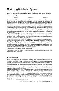
3. Problem Analysis This section identifies and analyses the following basic requirements, which are essential to our goals: • Accuracy - relates directly to the granularity of the observed information, the frequency of the measurements and the information model of monitoring events; • Expressive power - enables precise verification techniques like conformance testing using formal methods. The expressive power of the monitoring system rests on, for example, the ordering and causality information that can be retrieved from the generated monitoring events; • Applicability - has to do with the software development process, how easy it is to incorporate, manage and use the monitoring framework. Another important issue is the performance and flexibility of the system at runtime. We use the following terminology to further explain and discuss these requirements. The monitoring system operates on applications the targets that have been modified to facilitate a monitoring framework. A target consists of software units of distribution called entities. The framework monitors application behaviour and as a result produces monitoring events. With application behaviour we refer to the interaction patterns between the entities of an application. A process in this paper is equivalent to thread of execution. An execution environment corresponds to the operating system running on a computer wired to a communication network.
Entity A
Entity B
Contract (e.g. IDL)
Figure 2. Entities interacting through a contract. In Figure 2, entity A interacts with entity B using an interaction contract. The contract contains a set of services (IDL operations) that one of the entities explicitly provides (implements) and the other entity uses (invokes). In CORBA, the definition of interactions through a contract is unidirectional, unlike, for example, a bi-directional communication channel. Referring again to Figure 2, Entity A has the role of initiator that calls an operation on the implementation of the contract in entity B. We define the monitoring framework to observe entity interactions at the level of the contract. Every service in the contract is monitored and every value related to this service (IDL operation parameters and results) is recorded. The frequency of the measurements performed by the monitoring framework on the contract is determined by the monitored entities, which invoke services using this contract. The monitoring framework measures the interaction at the involved entities. Figure 3 shows the monitored points during entity interaction.
3.1 Interaction contracts Our major assumption is that the monitored distributed application consists of entities that interact with each other via a communication network (Figure 1). Distributed Application
Entity A
Entity C
Entity B
Entity A
Figure 1. Distributed application containing 3 entities.
Entity B
Monitored points
3
using ORB implementations that optimise interactions between collocated entities, so that the usage of the communication environment is circumvented. Note that only the thick arrows depict interaction between different entities and these interactions are observed by the monitoring framework.
Figure 3. Points of observation. Entity A interacts with B and itself. Since the design and the implementation of the application entities follow exactly the contract definition, the monitoring framework will be able to monitor any application designed and implemented with this middleware. The prerequisites are such, that the implementation of the monitoring framework conforms to the computational model of the middleware and the developers conform to the interaction contracts of the middleware.
Process A Process B
Execution Environment 1
Process C Process D
Process E
Execution Environment 2
3.2 Execution model Entity B
Entity A
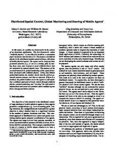
At any moment, distributed applications consist of a number of asynchronous processes that execute different tasks. Each process generates a sequential stream of events. The processes communicate by passing messages using the available communication environment [8]. The exchange of a message also generates events in each one of the participating processes. Without restrictions we assume that process execution and message transfer are asynchronous, and the communication environment is finite and unpredictable. The processes, messages and events comprise the execution model of the distributed application. The computational model of the middleware may influence the execution model of the distributed application. A typical example is how middleware implementations use different policies to assign processes to interactions between entities. In general, an interaction between two distributed entities can be mapped to a message exchange between two processes within these entities. Nevertheless, there are cases, in which entity interactions cannot be mapped to process message exchange, as for example when two entities share the same execution environment. Processes, which act on an entity concurrently, are called collocated processes. Furthermore, entities can be collocated in the same execution environment. Normally, execution environment corresponds to the operating system running on a physical node, however, in some cases, e.g., the Java Virtual Machine, it is possible to run several execution environments on one physical node. We take collocation into account as it relates directly to sharing common resources, e.g., memory space. Figure 4 shows how several entities interact. Processes A, B are collocated processes, as are C, D and E, whereas entity B and C are collocated entities. Process C finishes after sending "Msg 2" to process D, which is created at the time the message is sent to it, and dies after sending a message to process E. Process D is shared between entities and performs a direct method call ("Msg 3") across the boundaries of entities. This example comes from our experience
Msg 1 Msg 2 Msg 3
Entity C
Figure 4. Entities and processes deployed over execution environments. 3.2.1 Order of events The monitoring framework captures its measurements into standalone events that can be stored to persistent media or can be sent to a consumer application (monitor) that further analyses them. In the monitored system, these events are generated in a particular order. Distributed systems often operate in an environment of network delays and other unpredictable factors that may lead to receiving events in a different order than the order in which they were generated. There are different approaches that deal with the ordering problem. We concentrate on solutions using a timestamp that is recorded in the event. Processes can use the physical computer clock to issue timestamps. The contemporary hardware offers relatively accurate physical clocks for measuring the time. Nevertheless, even accurate clocks at different physical nodes may not be set to the same time. Our monitoring framework uses timestamps in a combination with a method for synchronising the clocks of the physical nodes. We assume that the error of the physical clock is insignificant in the short-term. The framework calculates the local clock offset to the clock of a well-known Network Time Protocol (NTP) server and this offset is used for calculating the physical timestamp of the monitoring events.
4
The physical timestamps provide total order of the monitoring events, however, they can prove inaccurate for some applications like conformance testing, where the order of events decides whether the application is built according to the behaviour model. Another approach offers an absolute order of events in a distributed system. It maintains a system of data structures called logical clocks. Every process maintains a logical clock that advances according to a special rule. When an event is generated inside a process, the value of its logical clock is recorded in the event as a logical timestamp. When a message is passed between two processes, the sender process tags the message with information about its logical clock. The receiver process uses this information to advance its logical clock. The actual advancement rule may vary. In the monitoring framework we use the rule of the logical vector clock technique that allows us to restore the order of the recorded events from the logical timestamp (See [8].) Note that the order relation of the logical timestamps is partial, since two messages in the system may be a result of concurrent execution of processes that have never exchanged information about their logical clocks (including indirect exchange through intermediate process). In this case the events will be ordered by using the inaccurate physical timestamp. The monitoring framework observes the distributed target application at the level of entities, therefore events are not generated for messages passed between collocated processes within the same entity. The only exception is when an entity interacts with itself. If the entities are to be considered black boxes (see 4.1), messages between collocated processes may not be tagged and the event order will be compromised, because the system of logical clocks guarantees order only when all the messages in the system are tagged according to the rule.
Process 1
Process 2
Entity A
T he events generated at these points of measurement are assigned a logical timestamp that is shared between processes within the Entity A.
Process 3
Entity B
T he message passed between these two non-collocated processes is tagged with ordering information that is used for determining the timestamp of the generated events.
Figure 5. How ordering information is propagated inside and between entities. To solve this problem, collocated processes can order their events, by employing synchronisation techniques on shared memory to avoid data corruption (Figure 5). Nevertheless, the shared memory synchronisation will become a bottleneck, if many concurrent processes are active. That is why we minimise the use of this approach to the boundaries of the entity. By sharing the logical clock all events in the entity will be ordered absolutely, thus all collocated processes can be regarded as one linear process communicating with other non-collocated processes. This way the logical clock solution is kept consistent. An alternative approach to solve the absolute order approach in an accurate way, is making processes communicate with a central ’scheduling’ object that will issue accurate timestamps for each event. This approach is similar to the shared memory, except it is distributed and the chances for a bottleneck are greater. That is why we do not consider this solution in our monitoring framework. 3.2.2 Causality The monitoring of causality is useful to assess the correct working of applications. For example, during the testing phase of the software development process, the causal relation between recorded monitoring events helps the tester to reason about the actual source of runtime errors. In an execution environment of asynchronous processes, the order relation provided by the logical clocks is also a causal relation. However, the shared
5
memory solution to retrieve ordering information within an entity does not allow one to keep track of causal relations anymore, since delays are introduced as a result of applying a scheme for sequential access to the shared logical clock. After investigating several particular technologies, like the Java platform and the CORBA Interceptor standard, we have developed a technique for propagating the ordering information between collocated processes within the same entity. This technique allows us to restore causality information in a generic way, without entering a conflict with a blackbox approach.
Component A
4. Technology solutions
Component B
Figure 6. DSC components interacting through synchronous invocations. Component A is the initiator while Component B provides the implementation.
In this section we investigate available technologies that can be used to build the monitoring framework, and we outline the software architecture of our prototype.
The process semantics behind the synchronous and asynchronous invocations is not explicitly defined in the CORBA standard. Figure 4 shows that sometimes messages passed between software entities are not messages between processes and this depends only on the deployment of the software entities, e.g. whether they are collocated within the same execution environment or not. We consider the component as a black-box designed and implemented by a third-party following a particular component model. Observable events, which occur in a component, are its lifecycle events and its interaction events. Lifecycle events, for example, are events that relate to creation and destruction of a component instance, announcement of explicit dependencies and implemented interfaces, suspend or resume of component instances, etc. Lifecycle events occur within one process and are not related to the communication between processes. These events receive their timestamps by using the shared memory scheme. Interaction events are a result from an invocation of an operation from one component on an IDL interface implemented by another component. To order the monitoring events, the monitoring framework relies on propagating monitoring information along with the invocations between components.
4.1 Black-box approach An entity is a software module that can be instantiated and configured as a part of an application. Deciding what is the granularity of the entity in the model influences the granularity of the monitoring system. Note that granularity does not really put restrictions on the monitoring system as the entity based observation model does not have a notion of what is in the entity. Entity candidates in our system are CORBA objects (each one implementing a single interface) and software components (based on a particular component model [4]). When we started this work, we had the DSC distributed software component framework [2] available. DSC offers a component model similar to the CORBA component model [7], allowing rapid design and development of distributed components. Although the software components can be rather large entities, we have chosen for this level of granularity for three reasons: (1) Component technology enters the software industry at a fast pace. (2) We had an advanced component framework available for experiments. (3) By definition, components can be approached as black boxes [4]. DSC components use the CORBA middleware as distributed processing environment. In CORBA, interaction is done through invoking operations on an interface implementation. Furthermore, invocations can be synchronous and asynchronous.
4.2 Context Propagation In order to trace the propagation of an invocation through the system, each invocation is transparently tagged with context information, which is updated at each monitoring point. The context is a data structure that encapsulates value of a logical clock, causality information, etc. The context is propagated between interacting components. Two particular problems have to be solved with respect to the context propagation:
6
•
monitoring framework can only partially restore causality relations between monitoring events. The CORBA POA specification defines the execution semantics of the CORBA invocation. ORB implementations that conform to POA always call the stubs in skeletons. This allows us to correctly generate interaction events when the ORB performs invocation optimisation for collocated components, i.e. one process handles the component interaction.
Sending context from one component to another, in a generic way; • Propagating context through the black box of the custom component implementation, in a generic way. Reflective technology allows us to isolate the monitoring specific code into separate facilities and libraries, that will leave component developers free of concerns about the monitoring during design and implementation phases. In our approach we have investigated three technologies: • CORBA Interceptors; • Reflection on the thread model through Java; • CORBA Portable Object Adapter (POA). CORBA provides the interceptor mechanism to reflect on the invocation model by offering low level access to the CORBA request/reply object. Our monitoring scheme uses interceptors (message and process level) to pass monitoring context between components. The black box approach interferes with the mechanism for propagating context inside the components of the distributed application. For example, when an invocation enters a component, it may be assigned to a process executing custom code that creates a number of parallel processes, each one following arbitrary interaction patterns with other components (Figure 7). This custom code may be built by a third-party or in general is encapsulated in an offthe-shelf component. We use the ThreadLocal Java class to assign context to processes (threads of execution) in a generic way [9]. The advance of the logical clock follows the original rule. We also use the InheritableThreadLocal Java class to propagate the monitoring information when a process creates another process (typical ’fork’ in the execution) inside the black box.
4.3 Configurability Our implementation of the monitoring framework employs techniques like intercepting and tagging interactions between application components, generating and sending monitoring events to consumer applications (Figure 8), and others. This behaviour translates into high CPU utilisation and frequent network transfers of monitoring events. Thus depending on the number of application components being monitored per execution environment and in the whole system, the overall performance of the target application is lower and the system may degrade to an unacceptable level. We believe the solution to the performance problem is in a flexible monitoring framework, that does not employ bottleneck solutions. Configurability of the monitoring architecture in the component can be used to lower the CPU utilisation in the physical node where components execute.
Event Consumer Event Consumer Component A
Process A Process B
Component B Component C
Component create
Figure 8. Components produce events destined for the event consumer applications. Inside the component, we define two types of configurability: static and dynamic. Static configurability comprises reconfiguration activities that require stopping, reconfiguring (e.g. recompiling) and restarting of the component instances. The process is supported by monitoring tools. Depending on the IDL and a static description of what should be monitored inside, such tools determine whether component code will be modified to produce monitoring events or not.
Figure 7. Process assigned to an incoming invocation creates a second process. Nevertheless, a generic scheme for tagging messages between threads of execution within the Java Virtual Machine is not available. For example, reflection on the message exchange (i.e. synchronisation) between threads of execution allows us to propagate context within the component implementation. The current prototype of our
7
monitoring architecture is based on the Portable Stub and Skeleton architecture as defined in [12].
Dynamic configurability does not require stopping and restarting of the component instances. Instead of this, the component implements a special interface that allows dynamic reconfiguration of the internal monitoring architecture, e.g., what for message types will be produced, turning on/off interception of particular interfaces, etc. Dynamic configuration is preferable, because it does not put restrictions on the lifecycle of the components. Nevertheless, we choose to split configuration into static and dynamic, because some of the technologies (particular ORB implementations, Java, C++ compilers) allow only a static approach to some of the reconfiguration schemes, as for example the activation of interceptors. Moreover, when we choose not to monitor a system, a performance increase may be achieved with the help of static reconfiguration by removing all monitoring hooks. Another way of reducing workload at the components is to decouple components that act as event producers from event consumers. Decoupling can be achieved by using an event service like the CORBA notification service, such that components do not have to hold references to the event consumers anymore. Instead, a reference to the event channel is held and events are sent only once to the channel, compared to the solution where several consumers must explicitly be notified of the same event. Decoupling also increases the scalability of the monitoring framework and thus of the applications facilitated by the framework. The CORBA notification service standard defines event filters. These filters encapsulate the request of the consumer application for particular events. Furthermore, event filters are propagated from the consumer through the notification service, to the sources of events - the components (Figure 9). The monitoring framework can use the event filters for dynamic reconfiguration at the components.
Component A
Component execution environment
Loc alM onitor
lt e
r
Ev en
F il
te r
LocalMonitor
ThreadContex t pushContext() popContex t()
preS keletonInvoke() pos tS k eletonInvok e() preS tubInvok e() pos tS tubInvoke()
preS k eletonInvok e() postS keletonInvoke() preS tubInvoke() postS tubInvok e()
ThreadCont ext xx xP OA
xx xImpl operation_x ()
_y yy S tub
O RB
operatio n_y ()
yy yP OA _invoke()
Skeleton
pushCont ext () popCont ext()
_invoke()
Component XXX uses interc eptors to propagate flow contex t
y yy Impl opera tion_y()
Component YYY
Figure 10. Monitoring class diagram of component XXX invoking operation on an interface YYY of component YYY. The IDL compiler generates a pair of Stub and Skeleton classes for each interface type encountered in the IDL specification file. The Skeleton class is the base class from which the user-created implementation class must inherit. The Skeleton class contains an _invoke() operation that has the following signature: public org.omg.CORBA.portable.OutputStream _invoke(String method, org.omg.CORBA.portable.InputStream input, org.omg.CORBA.portable.ResponseHandler handler) throws org.omg.CORBA.SystemException;
The body of the _invoke operation tests the value of parameter method, extracts the method parameters from the input parameter and invokes the method in the implementation class, see also Figure 10. The Stub class is used as a local proxy for a (possibly) remote object. It implements all the operations of the target CORBA object. Within usercreated implementation code a reference to a Stub object is obtained by narrowing a CORBA object reference to the appropriate type. When an operation is invoked on the Stub object, a CORBA request is assembled which contains the name of the operation, its parameter values and the destination. The request is further translated into an IIOP request and transmitted over the network by the ORB. The Skeleton and Stub classes mark the entry and exit points of an invocation on a component interface. Custom monitoring interceptor code executes just before and after each invocation, generates context information and prepares
Ev en t
Even t
Fi
Component C
m onitorE vent()
Event Consumer
t en Ev Component B
CentralMonitor
t
Event Consumer
Figure 9. Events and Event filters are delivered through the notification service.
4.4 Modular architecture The architecture of the monitoring framework is modular and scalable. Inside the components, the
8
a monitoring event. Once the system is sufficiently tested, the monitoring code can be removed by recompiling the IDL files without using the monitoring IDL compiler tool. ThreadContext objects take care of the propagation of the context within the component. The LocalMonitor objects encapsulate functionality for processing the monitoring events like, assigning the proper context to an event, queuing and scheduling events for delivery to the consumer applications (CentralizedMonitor), switching between different event delivery policies (direct send, using notification service, logging to local persistent media) and others. The CentralizedMonitor is an event consumer application that is capable of analysing, storing, and presenting monitoring events to the component tester.
4.6 Development process and test cases A distributed application can be a large composition of components, interacting with each other through their CORBA interfaces in a distributed environment. Figure 13 shows the DSC component development process.
Component specification (IDL, Descriptors)
Monitoring Events
The CentralizedMonitor component maintains several analysis tools (ObserverGUI objects) that analyse and represent event information properly to the component tester (Figure 11).
4.5 Information model A monitoring event is a persistent object that contains a number of data fields.
Logical Clock NTP Timestamp Trail Label
source_id source_type node_id container_id process_id
Information (determined by event type)
Interaction Events
Life-Cycle Events
interface_id interface_type operation_id parameters
announcement_id
Deployment & Usage (T esting)
DSC components are described in component specifications. A component specification is the input for the automated monitoring tools. Explicit dependencies and IDL types are the most important entries from the component specification, used during the component build and packaging phases for generation of the augmented with monitoring code stubs and skeletons (Figure 13). Once the components are packaged they can be deployed in an execution environment where monitoring tools are executed to observe the behaviour of the distributed component application. Application testers follow a common scenario: starting of all centralised monitor components, running the application and usage of the analysis tools provided by the centralised monitoring application. The central monitoring application is an event consumer specialised in collecting all events from the monitored system. From a GUI at the central monitor, the tester is able to select entry or exit (interaction) points of the component test subjects and to assign them textual label values.
Figure 11. The CentralizedMonitor event consumer.
Address
Build & Packaging
Figure 13. Phases of the component development process essential to the monitoring framework.
Obs erverGUI 1..*
Time
Implementation
Time
CentralizedM onitor EventPro ces sor
T emplate Generation
...others
Figure 12. Monitoring event structure The information model consists of three groups of fields: time, address, and information (Figure 12). The time group contains a fixed set of fields that captures ordering and causality information. The address group contains a fixed set of fields with information about the source of the event. The information group contains variable fields, depending on the event type. For example, an interaction event captures information about interface (interaction contract) id and type, operation name, and parameter values.
9
4.7 Prototype This section reports on different technology specific issues encountered during the implementation of the monitoring framework prototype. The prototype currently does not use a CORBA Notification Service because no suitable commercial or freeware implementations were available to us. 4.7.1 Object Request Brokers The ORBs: • • • •
monitoring framework supports the following Orbacus for Java 3.3 JacORB 1.0 beta 15 JavaORB 2.2.4 Visibroker for Java 3.4
The monitoring framework makes use of the POA and the Interceptors interfaces. We encountered many problems with incorrect implementations of the POA and Interceptor specifications resulting in a submission of a number of reports to the vendors (Visibroker, JacORB, JavaORB, Orbacus). 4.7.2 Service Contexts The mechanism for propagating context between the components has been implemented using CORBA Interceptors. The specification allows generic access to the assembled request object of the CORBA invocation. The CORBA request format contains a specific field for this purpose: the service context field. This field can hold an array of service contexts that is transparently passed from client to server and vice versa. Below is the Java declaration of the service context field in a CORBA request:
Figure 14. Message sequence diagram The label is then propagated with every interaction at each interaction point. The monitor records the events it receives to a persistent storage. Figure 14 shows a graphical representation used for creating Message Sequence Diagrams (MSD). Note that our notation an extention of a subset of the ITU notation for message sequence charts [6]. Figure 15 shows a tool that allows the application tester browse the parameters of the CORBA invocations.
Public org.omg.IOP.ServiceContext[] service_context;
Each service context consists of a numeric identifier and a sequence of bytes. In case of a request from client to server it is used to propagate information about the execution context of the client object to the server; in case of a CORBA reply it contains information about the execution context of the server object that may be examined by the client. Below is a part of the Java source code of the ServiceContext class: package org.omg.IOP; public final class ServiceContext implements org.omg.CORBA.portable.IDLEntity { public int context_id; public byte[] context_data;
A unique number was chosen to identify the DSC monitoring context in a sequence of service contexts. Figure 15. Visual interface for browsing complex CORBA IDL types.
10
monitoring framework supports several event types, ordering within multithreaded components, a tester tool for labelling invocations, support for different ORB implementations, and support for optimised invocations between collocated entities sharing one execution environment.
4.7.3 Interceptors At some point before the actual execution of a CORBA request (or reply) we need to insert the service context into the message. In a similar way we need to analyse the service context that was propagated back from server to client in the reply to the request. The custom CORBA interceptors we provide, insert the context in the request at the outgoing points and retrieve context at the incoming points. For a detailed explanation of interceptors the reader is referred to the ORB manuals or the OMG documents about interceptors [14]. DSC monitoring uses message-level interceptors, which provide low-level access to the CORBA request/reply at the following four points: • at the client side 1. before sending the request 2. after receiving the reply • at the server side 3. after receiving the request 4. before sending the reply
6. Conclusions We have succeeded to define a framework for the monitoring of component interactions that has sufficient expressive power, allowing formal analyses to be performed. The information generated by the framework accurately follows the interaction contract, which allows monitoring of virtually any application implemented using contracts. The monitoring framework seamlessly integrates in the component development process, by providing automated tool support for all activities related to monitoring. The technologies used to implement the prototype are standard, the framework is flexible and configurable. The emphasis of the proposed monitoring architecture is on dynamic reconfiguration of the monitoring output (through event filters) as opposed to static reconfiguration broadly suggested by previous work done in the area. The prototype of the monitoring framework is used for testing of services developed for a large application framework [10]. The component tester can make use of several facilities to track invocations, like the centralised monitor and the Message Sequence Diagram viewer.
Our framework performs instrumentation of the Stubs and Skeletons that can be replaced by the recently accepted Portable Interceptors submission [13], once implementations become available.
5. Related work In [8] Raynal gives an overview of the methods for capturing causality in distributed systems. He defines an execution model of processes that pass messages between each other. In this environment Raynal describes the logical clock schemes for capturing order and causality of messages. Our monitoring framework uses Raynal’s the technique, however, our execution environment has constraints such that not all messages can be tagged with the necessary information. After applying a shared memory solution for propagating context between the processes within an entity, our framework is capable to employ the logical clock technique and restore order. Nevertheless, because of the shared memory approach the causality relation in the execution model is broken and a separate solution is sought in order to track causality in the system. In [15] Logean describes a method for run-time monitoring of distributed applications that supports a software development process. His approach employs ordering technique deriving from logical clocks. The level of entity granularity is the CORBA object. Our monitoring framework enhances this approach with introduction of the entity. The configuration of the monitoring code in the Logean’s method can be dynamic and supported by tools. By applying notification service, our approach introduces additional scheme for decoupling event sources from event consumers. Additionally, the
6.1 Future work The current framework supports only partial capturing of causality. In order to improve the opportunities for performing formal analysis, we need to extend the causality support in the framework. Provided a formal model of the behaviour of a distributed system, conformance testing can be done assisted by a tool. For this purpose, a mapping has to be created from the execution model of the monitoring system to the formal model describing the system behaviour [16]. Furthermore, the monitoring framework can be generalised as a framework for extension of distributed applications with generic monitoring functionality. The ultimate goal is to define a flexible monitoring framework, that allows introduction of new application components into legacy distributed systems at reduced cost. All observation related functionality necessary for the operation of the new application components will be defined as reconfiguration of the monitoring code in the legacy system. For example, using our monitoring framework, introduction of an accounting facility can be achieved by reconfiguring the legacy components to produce only events related to the accounting domain.
11
We intend to develop a generic architecture for development of monitoring application components. Such application components use the basic event information model, combine it with a static data mapping and translate the monitoring information to a specific application domain. Referring to the accounting example, the monitoring events delivered to the accounting application components can be translated through a static mapping to the terminology of the accounting domain.
7. Acknowledgements The authors are grateful to Dick Quartel from Twente University, who provided valuable comments on the content of this paper.
References 1.
2.
3. 4. 5. 6. 7. 8. 9. 10. 11. 12. 13. 14. 15.
16.
Batteram, H.J., and H.P. Idzenga, “A Generic Software Component Framework for Distributed Communication Architectures,” ECSCW’97 Workshop on Object Oriented Groupware Platforms, 1997, Lancaster UK, pp. 68-73. Bakker, J.L., and H.J. Batteram, "Design and evaluation of the Distributed Software Component Framework for Distributed Communication Architectures", Proceedings of the 2nd international Workshop on Enterprise Distributed Object Computing (EDOC'98), pp. 282–288, San Diego (USA), November 3–5, 1998. The MESH project, see http://www.mesh.nl/ Szypersrki, C., Component Software: Beyond Object Oriented Programming, Addison-Wesley, 1998. Krawczyk, H., Wiszniewski, B., "Analysis and Testing of Distributed Software Applications", Research Studies Press Ltd., Baldock, Hertfordshire, England, 1998. Message Sequence Chart (MSC), ITU-T Z.120, Telecommunication Standardisation Sector of ITU, October, 1996. CORBA Component Model RFP, orbos/97-06-12, Revised Submission, February 2000. Raynal, M., Singhal, M., "Logical Time: Capturing Causality in Distributed Systems", IEEE Computer 29, pp. 49-57, February 1996. Java 2 Platform, Standard Edition, API specification, http://java.sun.com/products/jdk/1.2/docs/api/ The FRIENDS project, see http://friends.gigaport.nl/ The AMIDST project, see http://amidst.ctit.utwente.nl/ IDL to Java Mapping, Java ORB Portability Interfaces, OMG TC Document formal/99-07-53, June 1999. Portable Interceptors, OMG TC Document orbosl/9912-02, December 1999. CORBA 2.3 chapter 21, Interceptors, OMG TC Document formal/99-07-25, July 1999. Logean, X., Dietrich, F., Karamyan, H. and Koppenhoefer, S., "Run-time Monitoring of Distributed Applications", Proceedings of the IFIP International Conference on Distributed Systems Platforms and Open Distributed Processing (Middleware'98), pp. 459-473, Hudson River Valley, New York, USA, 3-7 April 2000. Quartel, D.A.C., M.J. van Sinderen, and L. Ferreira Pires, "A model-based approach to service creation", In: Proceedings of the Seventh IEEE Computer Society Workshop on Future Trends of Distributed Computing Systems, IEEE Computer Society, 1999, 102-110.
12