Multi-DOF Micro-Macro Bilateral Controller Using ... - IEEE Xplore
Recommend Documents
23, NO. 5, MAY 2016. On Fast Bilateral Filtering Using Fourier Kernels. Sanjay Ghosh, Student Member, IEEE, and Kunal N. Chaudhury, Senior Member, IEEE.
Using the Power-Flow Control and the Ideal. Phase-Shifter Methods. Nicklas Johansson, Member, IEEE, Lennart Ãngquist, Member, IEEE, and Hans-Peter Nee, ...
A New Iterative Learning Controller Using Variable. Structure Fourier Neural Network. Wei Zuo and Lilong Cai, Member, IEEE. AbstractâA new iterative learning ...
Jun 6, 2018 - commands from the brain to a machine by using motor signals generated .... hand movements, on the basis of a time series and event-related.
Decentralized Power System Damping Controller. Design using Hâ Loop-shaping Technique. Nilesh Modi, T. K. Saha & N. Mithulananthan. School of ...
A new model namely edge dynamics representing the differences on connected agents' states is first presented. Then the distributed con- sensus controller ...
Las Vegas, Nevada 89154-4026A ... on factory assembly line or lighting fixtures. This paper ... assembly line, lighting fixtures, traffic control system, or even.
Programmable Logic Controller Forensics. Irfan Ahmed | University of New Orleans. Sebastian Obermeier | ABB. Sneha Sudhakaran and Vassil Roussev ...
Humberto E. Garcia, Asok Ray and Robert M. Edwards. A deaerating feedwater heater, equipped with a water level controller and a pressure controller, has ...
example, the CDN's DNS redirection technique can help a peer to find the nearest peer to itself, but cannot help the network operators to do fine-grained traffic ...
functional electric stimulation (FES) could improve hand function in stroke patients. In this study, we attempt to combine. BAT with FES applying to the post-stroke ...
segment a target brain pathology. The detection of pathological difference left to right in brain imagery is complicated by normal variations as well as geometric.
AbstractâIn masterâslave teleoperation applications that deal with a delicate and sensitive environment, it is important to provide haptic feedback of ...
Dec 3, 2016 - Chuanjie Lin, Chuanyang Li, Jinliang He, Jun Hu and Bo Zhang. State Key Laboratory of Power Systems, Department of Electrical Engineering.
and forward markets, consisting of energy contracts offered between generators with fuel-based sources, suppliers acting as intermediaries and consumers with ...
AbstractâThe ankles play an important role in human balance. In most studies investigating balance control the contribution of the left and right leg is not ...
Email: [email protected]. Abstract âThis paper presents controller design based on state-space pole-placement method for a non-linear dynamic.
phenomenon in disc brake model using an active force control. (AFC) strategy. A two degree-of-freedom (2-DOF) Wagner model was considered in the study as ...
Dec 22, 2015 - Thapar University, Patiala, Punjab, India e.mail: [email protected]. Sanjay Gairola. Dept. of Electrical and Electronics Engineering. NIET ...
based shunt Flexible AC Transmission Systems (FACTS) devices which can control the line voltage at the point of connection to the electric power network.
transmission grid applications. ... flexible AC transmission system (FACTS) ... The ac winding element which can be connected into an ac t system. The dc ...
Oct 31, 2012 - generate high direct current (DC) voltages for device actuation with low ... The authors demonstrate the design of the high-voltage (HV) SC ...
Abstract: Present distribution network voltage design practice limits the distributed ... more active approach to network voltage control can significantly increase ...
Multi-DOF Micro-Macro Bilateral Controller Using ... - IEEE Xplore
IEEE TRANSACTIONS ON INDUSTRIAL INFORMATICS, VOL. 7, NO. 3, AUGUST 2011
Multi-DOF Micro-Macro Bilateral Controller Using Oblique Coordinate Control Sho Sakaino, Student Member, IEEE, Tomoya Sato, Student Member, IEEE, and Kouhei Ohnishi, Fellow, IEEE
Abstract—In this study, we show that tasks can be realized by appropriate coordinate transformation. This approach, oblique coordinate control, decouples tasks. Even though a system is large, they can be designed by a combination of small tasks. Therefore, tasks can be regarded as reusable components. In this study, micro-macro bilateral control is achieved as a complicated task. Small objects can be manipulated as large objects in micro-macro bilateral control. However, ideal micro-macro bilateral controllers are usually derived only for single-degree-of-freedom (DOF) systems. Then, we propose a micro-macro bilateral controller for multi-DOF on the basis of oblique coordinate control. To obtain multi-DOF bilateral control, we first derive control goals as kinematic relations. This study also considers the case where scaling gains of position and force are selected in a different manner. The goals of micro-macro bilateral control are then controlled by oblique coordinate control. The validity of the proposed method is experimentally verified. Index Terms—Acceleration control, bilateral control, haptics, micro-macro bilateral control, oblique coordinate control.
I. INTRODUCTION
R
ECENTLY, robots have been utilized not only in factories (closed environments) but also in human societies (open environments). In particular, robotic surgery is a new exciting research field in which many papers have been published. Minimally invasive surgery (MIS) is one such application of robotic surgery in which operations causing minimal damage to patients can be performed [1]–[3]. A conventional problem of MIS is that operators have difficulty experiencing the actual reaction force from the environment (organs of patients), although some researchers have tried to transmit such environmental forces. In the absence of force transmission, medical operations are difficult and operators are likely to harm organs. To overcome this problem, we propose bilateral control to realize communications of our tactile sensations. Manuscript received January 10, 2011; revised February 22, 2011; accepted April 18, 2011. Date of publication July 12, 2011; date of current version August 10, 2011. This work was supported in part by the Ministry of Education, Culture, Sports, Science and Technology of Japan under Grant-in-Aid for Scientific Research (S), 20226007, 2008. This paper was presented in part at International Conference on Mechatronics, Malaga, Spain, 2009. Personal use of this material is permitted. However, permission to use this material for any other purposes must be obtained from the IEEE by sending a request to [email protected]. Paper no. TII-11-01-0010. The authors are with Ohnishi Laboratory, Department of System Design Engineering, Keio University, 3-14-1, Hiyoshi, Kohoku-ku, Yokohama 223-8522, Japan (e-mail: [email protected]; [email protected]; [email protected]). Color versions of one or more of the figures in this paper are available online at http://ieeexplore.ieee.org. Digital Object Identifier 10.1109/TII.2011.2158837
Lawrence proposed “Transparency” as an index for tactile sensation [4]. Although many researchers have tried to improve transparency, ideal transparency have not yet been obtained [5], [6], [7]. Yokokohji et al. proposed a four-channel bilateral controller, which obtained ideal transparency only in the absence of disturbance [8]. They found that the goals of controller performing bilateral control are divided in two tasks. The first task is that the position difference between local (master) and remote (slave) robots should be zero. The second task is that the summation of the forces of the master and slave robots should be zero. This condition represents the law of action and reaction. Matsumoto et al., improved the four-channel bilateral controller [9] and eliminated disturbances by using a disturbance observer (DOB) [10]. The DOB is widely used to improve performance of control systems [11], [12]. Tavakoli et al. compared and analyzed four-channel bilateral control systems [13]. Some researchers investigated bilateral controllers for different structures [14], [15]. Some researchers reported bilateral control under time-delay [16], [17], [18]. A way to analyze absolute stability of bilateral control was reported by Haddadi et al. [19]. As a next step in developing bilateral control, micro-macro bilateral control was proposed. In the bilateral controller, the motion of the slave robot is scaled relative to that of the master robot such that small and thin tissues can be regarded as large and thick, respectively. This technique allows fine-scale MIS, which is essential for brain surgery [20] and cell manipulation [21], [22], [23]. Colgate accomplished micro-macro bilateral control by scaling the motion of robots by varying power and impedance [24]. Kaneko et al. also investigated impedance shaping [25]. Takeo et al. proposed a micro-macro teleoperation system without using force sensors [26]. Sano et al. stabilized a theory [27]. Such micro-macro teleoperation system using methods, however, cannot realize sufficient force transmission for MIS. Kaneko et al. proposed a micro-macro system with force feedback, but the contacting environments assumed in this research were virtual; therefore, their technique cannot be applied to real world surgical environments [28]. Some researchers realized micro-macro bilateral controllers by using sliding-mode controllers [29], [30]. Shimono et al. proposed a micro-macro bilateral controller based on the DOB [31]. However, these methods do not consider kinetic and dynamic effects of scaling gains and their transparency is not ideal. Susa et al. improved Shimono’s method and obtained a micro-macro bilateral controller with ideal transparency [32], [33]. Although transparency of a micro-macro bilateral controller based on the DOB was improved, the designing of such a controller is still difficult and ambiguous. Therefore, an ideal micro-macro bilateral controller for multi-degree-of-freedom (DOF) systems
SAKAINO et al.: MULTI-DOF MICRO-MACRO BILATERAL CONTROLLER USING OBLIQUE COORDINATE CONTROL
has not been derived, and the practical realization of such a controller is almost impossible. This is a significant problem in actual robotic surgery, because medical robots usually need many DOFs. In the precious studies, we proposed oblique coordinate control [34], and found that micro-macro bilateral control can be simply treated as a position/force hybrid control problem in an appropriate coordinate system. Oblique coordinate control treats tasks as coordinate transformation and precisely unifies position and force control references; owing to this characteristic, definition of tasks and the design of the controllers can be independently obtained. Therefore, designers can easily realize ideal controllers for complicated tasks, which have been difficult for the conventional controllers. However, only micro-macro bilateral control between single-DOF systems has been discussed [34]. In addition, the scaling gains of position and force have been restricted to be the same value. If the gains can be changed, the impedance of organs can also be changed. This would be useful for palpation and improvement of safety. In this study, we propose a micro-macro bilateral controller for multi-DOF systems. Moreover, the scaling gains can be independently selected. Brief analyses of the proposed method are discussed and its validity is experimentally verified. Even though tasks and robot systems are more complicated than the conventional situation [34], stable and precise micro-macro bilateral control is achieved because position and force tasks are decoupled by oblique coordinate control. In oblique coordinate control, once an appropriate coordinate system is found, it can be reused to other systems with few efforts. Large and complicate tasks are substituted for a combination of small tasks. More specifically, a single-DOF micro-macro bilateral control is easily extended to a multi-DOF micro-macro bilateral control. Because the DOB improves the robustness, disturbances, such as modeling errors, friction, and gravitational forces show few effects on tasks. This study is composed of six sections. Modeling of robots is discussed in Section II. In Section III, the micro-macro bilateral controller is proposed. The controller is analyzed in Section IV. The validity of the proposed method is confirmed by experiments in Section V. In the last section, this study is summarized.
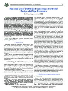
Fig. 1. Master robot.
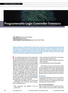
Fig. 2. Slave robot.
II. MODELING In this study, we used two DOF linear surgical forceps robots, as shown in Figs. 1 and 2, as an example of the multi-DOF robots. Figs. 3 and 4 show schematic models of the robots. are the position, force, and mass The variables, , , and of the actuators, respectively.
Fig. 3. Master robot model.
A. Kinematics The tip positions of the forceps are controlled by the lower actuators. Therefore, the tip positions of the lower actuators are and , respectively. The open-close motion is generated by the upper actuators, whose relative positions from the lower and , respectively. Therefore, the absolute actuators are and , tip positions of the upper actuators are respectively.
Fig. 4. Slave robot model.
447
448
IEEE TRANSACTIONS ON INDUSTRIAL INFORMATICS, VOL. 7, NO. 3, AUGUST 2011
B. Dynamics The Lagrangian of the master robot is given as follows: (1) Fig. 5. Micro-macro bilateral control.
The motion equations are derived from the Lagrange equation (2) (3) Next, these equations can be expressed in vector and matrix forms (4) (5)
is the scaling gain of force. The difference between the proposed and previous controllers is that and can be independently set in the proposed controller, but not in the previous controllers discussed in [34]. Therefore, the impedance that the operators feel can be modified in the proposed method. A modal space is a space in which the tasks are described. In this space, the realization of tasks is regarded as a position/force is hybrid control problem. A position task vector defined as follows:
(6) (16) Similarly, the motion equations of the slave robot are derived as follows:
Simultaneously, the task in the velocity dimension is given as follows:
(7) (8)
(17) (18)
(9) Here, and are the mass matrices of the master and slave robots, respectively. Next, the dynamics of the actuators shown in (4) and (7) are simplified as follows: (10) (11) (12)
is the unit matrix. A force task vector Here, given as follows:
is also
(19) (20) is introduced to Next, a “task Jacobian matrix” unify the above two tasks. The task Jacobian matrix should be regular
(13) (21) where is a zero matrix. The dynamics of general multi-link robots is discussed in the Appendix. III. MICRO-MACRO BILATERAL CONTROLLER In this section, the proposed micro-macro bilateral controller is derived using oblique coordinate control. A. Task Description In oblique coordinate control, tasks are defined as the kinematics. Fig. 5 shows a schematic representation of micro-macro bilateral control. The two equations in Fig. 5 are the control goals of the micro-macro bilateral control. The first equation represents position tracking (14) Here, is the scaling gain of position. The second equation reflects the law of action and reaction (15)
The position and force in the modal space, which is the vector space after the transformation by the task Jacobian matrix are defined as follows: (22) Here, and are a position vector related to force tasks and a force vector related to position tasks, respectively. These parameters are not directly related to the control goals. The task vectors are transformed by the task Jacobian matrix (23) (24) (25) . The force vectors are usually transformed by On the other hand, in the modal space, force vectors are transformed using the transformation of velocity. It makes designing of the tasks easy. As a result of this transformation, the energies before and after the modal transformation differ.
SAKAINO et al.: MULTI-DOF MICRO-MACRO BILATERAL CONTROLLER USING OBLIQUE COORDINATE CONTROL
449
Fig. 6. Transformation of references.
B. Dynamics The dynamics in the modal space is given by (10), (24), and (25) (26) (27)
Fig. 7. Hybrid controller in oblique coordinate.
is obtained using a hybrid matrix its schematic. system [34]. The matrix is derived from (32)
of the
(28) (29) (33) Here, is a “task mass matrix,” which gives the dynamic relation between each task. Off-diagonal parameters of this matrix express the interference between the tasks.
(34) (35)
C. Controller Design In this study, as an example of position and force controllers, the acceleration and force references are determined by a proportional-derivative controller and a proportional controller, respectively
Next, the force reference is then calculated as follows: (36) (37)
(30)
(38)
(31) Here, the superscripts “ref” and “res” denote reference and response values, respectively. The parameters , , and are the control gains. Generally, other position and force controllers can be implemented. Our main proposals are, the way to describe tasks and the way to unify position and force control references. The selection of controllers is not main contribution of this study. Disturbances existing in the actuator space are eliminated by the DOB. The overall block diagram is shown in Fig. 7. Then, the way to unify the position and force references is shown. The tasks are decoupled by this procedure. Considering (27), the references should satisfy the following relation [34]:
Here, is the position/force selection matrix. Finally, control inputs of the actuators are derived as follows: (39)
IV. ANALYSIS In this section, first, the performance and stability of the proposed method are analyzed. Then, the robustness is discussed. A. Performance and Stability
(32)
The disturbances existing in the actuator space are eliminated by the DOB. When the DOB is implemented in the actuator space, the dynamics in the Laplace domain can be written as follows [10]:
To calculate the control inputs given in the force dimension, the two references and should be unified in the force dimension. In other words, the combination of and should be transformed to that of and . Fig. 6 shows
(40) (41)
450
IEEE TRANSACTIONS ON INDUSTRIAL INFORMATICS, VOL. 7, NO. 3, AUGUST 2011
Here, and are the disturbance term and the modeling error term, respectively. is the cutoff angular frequency of the DOB. By using (40), the dynamics in the modal space is derived as follows: (42)
Equation (49) and (51) yield the force response in the modal space as follows:
(54) The characteristic equation of this system is given as follows: (55)
(43) 1) Position Response: The position response is analyzed here. Equations (30), (32), and (42) yield the following:
(44) (45)
This equation indicates that the stability of the system depends . In practice, hands of human only on the damping matrix operators have sufficient damping characteristics, which make sufficiently high, and the (54) stable. We can usually set in (54) is negligibly small. Thus, the stable influence of and precise force responses are obtained in our proposed method. If a stricter stability is needed, we would need to insert a damping term into the force controller, which results in a tradeoff, wherein the regulation performance of the force controller will be degraded.
(46)
B. Robustness
(47)
In this section, robustness to modeling errors of is discussed. Force responses does not deteriorate by the modeling errors because the force task is controlled without as shown in (49). Therefore, only position responses are analyzed in this study. Assuming that there are no disturbances except for modeling errors, the dynamics (42) is given as follows:
From (47), the position response is; therefore, given by a stable third-order system. Furthermore, because there is no effect of force controller, the position and force tasks are decoupled. 2) Force Response: The force response is analyzed here. Similarly, to the position response, the force response is given by (31) and (42)
(56) (57)
(48)
is a nominal task mass matrix, and is a modeling error term. Then, the acceleration and force references are derived with the following relation: (58)
(49)
Equation (47), (56), and (58) yield the responses in the presence of modeling errors as follows:
Note that even though there is the effect of inertial force in the first term on the right-hand side of (49), there is no effect of position controller. Therefore, position and force tasks can be independently designed. In this study, we assume that the reaction force is given by a spring-damper model
(59)
(50) Here, and are the elastic and damping coefficients of the environment, respectively. Next, the force response in the modal space is given as follows: (51) (52) (53)
(60) (61) The robust stability can be designed by . In this study, we assume that modeling errors were small so that it can be suppressed by the DOB. Note that this is practically valid assumption [9]–[12], [14]–[17], [31]–[35]. V. EXPERIMENT In this experiment, the slave robots grasped a piece of sponge as a soft object and an aluminum block as a hard object. We examined the following three cases. . • Case 1: soft object . • Case 2: hard object . • Case 3: soft object
SAKAINO et al.: MULTI-DOF MICRO-MACRO BILATERAL CONTROLLER USING OBLIQUE COORDINATE CONTROL
451
TABLE I CONTROL PARAMETERS
Fig. 9. Position response (soft, (b) Master 2 and Slave 2.
Fig. 8. Force response (soft, 1. (b) Master 2 and Slave 2.
= 3; = 3). (a) Master 1 and Slave
The operating system used in this study was RT-Linux 3.2 on Red Hat Linux 9. The positions and the reaction forces of the actuators were measured by optical encoders (1 pulse per 0.0001 m) and a reaction force observer (RFOB) [36]. The force resolution of the RFOB was 0.002N realizing wide-band force sensing. Because the bandwidth of the RFOB is superior to that of the force sensors [35], the RFOB is suitable for bilateral control, which requires highly precise force control. An operator experienced the grasping force through bilateral control. Table I shows the control parameters. The proportionalderivative controller was set to critical damping. The natural angular frequency was set as 30 [rad/s]. Because the position controller transmits the human motion of the master side to the slave side, the natural angular frequency was set to cover the frequency of the human motion, which in practice is less than
= 3; = 3). (a) Master 1 and Slave 1.
4 [Hz] ( [rad/s]). The cutoff angular frequency of the DOB and the RFOB was set to cover the cutoff angular frequency of the tactile sensation. In practice, it is very difficult for us to distinguish the high-frequency force over 200 [rad/s]. The sampling period was set as short as possible. In this study, only the experimental results of the proposed method are discussed for the following two reasons. First, the tracking performance of the proposed method has already been compared to the conventional method [34]. Second, because the tracking performance of the conventional methods is considerably poor, multi-DOF micro-macro bilateral control has been difficult to realize using conventional methods, which have to be conservative to assure stability. Figs. 8 and 9 are the experimental results for Case 1. Figs. 10 and 11 are the experimental results for Case 2. Figs. 12 and 13 are the experimental results for Case 3. In each figure, the solid and dashed lines show the responses of the master and times scaled for comparison. slave robots, which are or Figs. 8–12 show the force responses, whereas Figs. 9–13 show the position responses. The tip positions and force responses are shown in Figs. 8(a)–13(a), and the open-close motions are shown in Figs. 8(b)–13(b). From Figs. 8–11, the responses of the master and slave robots were almost equal. This shows that the proposed micro-macro bilateral controller is applicable and useful for multi-DOF
452
IEEE TRANSACTIONS ON INDUSTRIAL INFORMATICS, VOL. 7, NO. 3, AUGUST 2011
Fig. 10. Force response (hard, (b) Master 2 and Slave 2.
= 3; = 3). (a) Master 1 and Slave 1.
systems, because the interaction of the position and force tasks is strictly modeled in hybrid matrix . Without the matrix, the responses will be degraded. In addition, our proposed method is less dependent on environmental conditions, because the DOB successfully suppressed the influence of modeling errors. Figs. 12 and 13 show that in Case 3 the force and position responses of the master robot corresponded to those of the slave robot similar to Cases 1 and 2. In Case 3, the scaling gain of ); therefore, the the force task was three times greater ( operator experienced a three-times stiffer environment.
Fig. 11. Position response (hard, (b) Master 2 and Slave 2.
= 3; = 3). (a) Master 1 and Slave 1.
designers should concentrate their efforts only on finding tasks (coordinate transformation). When a useful task is found and realized in a system, the tasks can be implemented to another system without caring interferences of tasks. Designing efforts will be drastically reduced by oblique coordinate control.
APPENDIX In general, in the modeling of multi-link (n-link) manipulators, there are many disturbances, such as centrifugal and Coriolis forces and gravitational force. Then, the dynamics of a multi-link master robot is given as follows: [37]
VI. CONCLUSION In this study, a micro-macro bilateral controller for multi-DOF systems was proposed. The scaling gains of both of position and force can be independently selected in the proposed method. The experimental results verified that the proposed method is applicable for actual robot systems, which is necessary for advanced and sophisticated medical operations. In addition, the adaptability of oblique coordinate control was also confirmed. Because the robustness of systems is powerfully guaranteed by the DOB, stable and precise responses were obtained with few adjustments. In oblique coordinate control,
(62) Here, and are an -dimensional position vector and a is gravitational force vector, respectively. The parameter force. Then, the dynamics can be rewritten as follows:
(63) (64)
SAKAINO et al.: MULTI-DOF MICRO-MACRO BILATERAL CONTROLLER USING OBLIQUE COORDINATE CONTROL
Fig. 12. Force response (soft, (b) Master 2 and Slave 2.
453
= 1; = 3). (a) Master 1 and Slave 1.
is a disturbance term including centrifugal and Coriolis forces and gravitational force. The dynamics of a multi-link slave robot is given in the same way
Fig. 13. Position response (soft, (b) Master 2 and Slave 2.
= 1; = 3). (a) Master 1 and Slave 1.
(74) (65) (66) and are -dimensional position vector and force vector, is gravitational force. Then, the respectively. The parameter dynamics of master and slave robots is derived
By using the DOB, centrifugal and Coriolis forces and gravitational force can be treated as being passed through high-pass filters and their effects are suppressed with the DOB [10], [11], [12]. Therefore, their effects in the Laplace frequency domain can be similarly written in (42). Because, in practice, the cutoff angular frequency of the DOB can be set sufficiently high, the proposed method is applicable to multi-link manipulators.
(67) (68) (69) (70) (71) The dynamics in the modal space is derived from (24), (25), and (67), as follows: (72) (73)
REFERENCES [1] U. Hagn, T. Ortmaier, R. Konietschke, B. Kubler, U. Seibold, A. Tobergte, M. Nickl, S. Jorg, and G. Hirzinger, “Telemanipulator for remote minimally invasive surgery,” IEEE Robot. Autom. Mag., vol. 15, pp. 28–38, Dec. 2008. [2] C.-H. King, M. O. Culjat, M. L. Franco, J. W. Bisley, G. P. Carman, E. P. Dutson, and W. S. Grundfest, “A multielement tactile feedback system for robot-assisted minimally invasive surgery,” IEEE Trans. Haptics, vol. 2, pp. 52–56, Jan.-Mar. 2008. [3] C.-H. King, M. O. Culjat, M. L. Franco, C. E. Lewis, E. P. Dutson, W. S. Grundfest, and J. W. Bisley, “Tactile feedback induces reduced grasping force in robot-assisted surgery,” IEEE Trans. Haptics, vol. 2, pp. 103–110, Apr.-Jun. 2009. [4] D. A. Lawrence, “Stability and transparency in bilateral teleoperation,” IEEE Trans. Robot. Autom., vol. 9, no. 5, pp. 624–637, 1993.
454
IEEE TRANSACTIONS ON INDUSTRIAL INFORMATICS, VOL. 7, NO. 3, AUGUST 2011
[5] R. J. Anderson and M. W. Spong, “Bilateral control of teleoperators with time delay,” IEEE Trans. Autom. Control, vol. 34, no. 5, pp. 494–501, May 1989. [6] K. Hashtrudi-Zaad and S. E. Salcudean, “Bilateral parallel force/position teleoperation control,” J. Robot. Syst., vol. 19, no. 4, pp. 155–167, 2002. [7] M. Tavakoli, R. V. Patel, and M. Moallem, “A force-reflective masterslave system for minimally invasive surgery,” in Proc. IEEE/RSJ Int. Conf. Intell. Robot. Syst., 2003, vol. 4, pp. 3077–3082. [8] Y. Yokokohji and T. Yoshikawa, “Bilateral control of master-slave manipulators for ideal kinesthetic coupling—formulation and experiment,” IEEE Trans. Robot. Autom., vol. 10, no. 5, pp. 605–620, 1994. [9] Y. Matsumoto, S. Katsura, and K. Ohnishi, “An analysis and design of bilateral control based on disturbance observer,” in Proc. 10th IEEE Int. Conf. Ind. Technol., 2003, pp. 802–807. [10] K. Ohnishi, M. Shibata, and T. Murakami, “Motion control for advanced mechatronics,” IEEE/ASME Trans. Mechatronics, vol. 1, no. 1, pp. 56–67, Mar. 1996. [11] N. Motoi, M. Ikebe, and K. Ohnishi, “Real-time gait planning for pushing motion of humanoid robot,” IEEE Trans. Ind. Informat., vol. 3, no. 2, pp. 154–163, May 2007. [12] T. Shibata and T. Murakami, “Null space motion control by pid control considering passivity in redundant manipulator,” IEEE Trans. Ind. Informat., vol. 4, no. 4, pp. 261–270, Apr. 2008. [13] M. Tavakoli, A. Aziminejad, R. V. Patel, and M. Moallem, “High-fidelity bilateral teleoperation systems and the effect of multimodal haptics,” IEEE Trans. Syst., Man, Cybern., vol. 37, pp. 1512–1528, Dec. 2007. [14] R. Kubo and K. Ohnishi, “Hybrid control for multiple robots in grasping and manipulation,” in Proc. 12th Int. Power Electron. Motion Control Conf., Aug. 2006, pp. 367–372. [15] S. Sakaino, T. Sato, and K. Ohnishi, “Haptic communication between different structures with disturbance observer in modal space,” in Proc. Int. Workshop on Vision, Commun. Circuits, Nov. 2008, pp. 213–216. [16] K. Natori, R. Oboe, and K. Ohnishi, “Stability analysis and practical design procedure of time delayed control systems with communication disturbance observer,” IEEE Trans. Ind. Informat., vol. 4, no. 3, pp. 185–197, Aug. 2008. [17] K. Natori, T. Tuji, and K. Ohnishi, “Time-delay compensation by communication disturbance observer for bilateral teleoperation under timevarying delay,” IEEE Trans. Ind. Electron., vol. 57, pp. 1050–1061, Mar. 2010. [18] B. Yalcin and K. Ohnishi, “Stable and transparent time-delayed teleoperation by direct acceleration waves,” IEEE Trans. Ind. Electron., vol. 57, pp. 3228–3238, Sep. 2010. [19] A. Haddadi and K. Hashtrudi-Zaad, “Bounded-impedance absolute stability of bilateral teleoperation control systems,” IEEE Trans. Haptics, vol. 3, pp. 15–27, Mar. 2010. [20] S. E. Salcudean and J. Yan, “Toward a force-reflecting motion-scaling system for microsurgery,” in Proc. IEEE Int. Conf. Robot. Autom., May 1994, vol. 3, pp. 2296–2301. [21] M. Shuzo, H. Arai, R. Kanzaki, and I. Shimoyama, “A nano lead on a force sensing cantilever for bilateral manipulation of a single cell,” in Proc. IEEE Int. Conf. Solid-state Sensors, Actuators and Microsystems, 1993, vol. 2, pp. 1720–1723. [22] I. Gaponov, R. Jee-Hwan, C. Seong-Joo, C. Hyun-Chan, and Y. Poduraev, “Telerobotic system for cell manipulation,” in Proc. IEEE/ASME Int. Conf. Adv. Intell. Mechatronics, 2008, pp. 165–169. [23] K. Sung-Gaun and M. Sitti, “Task-based and stable telenanomanipulation in a nanoscale virtual environment,” IEEE Trans. Autom. Sci. Eng., vol. 3, no. 3, pp. 240–247, Aug. 2006. [24] J. E. Colgate, “Power and impedance scaling in bilateral manipulation,” in Proc. 1991 IEEE Int. Conf. Robot. Autom., 1991, pp. 2292–2297. [25] K. Kaneko, H. Tokashiki, K. Tanie, and K. Komoriya, “Impedance shaping based on force feedback bilateral control in macro-micro teleoperation system,” in Proc. 1997 IEEE Int. Conf. Robot. Autom., 1997, pp. 710–717. [26] K. Takeo and K. Kosuge, “Implementation of the micro-macro teleoperation system without using slave-side force sensors,” in Proc. IEEE Int. Conf. Robot. Autom., 1997, vol. 2, pp. 1600–1605. [27] A. Sano and H. Fujimoto, “Personal scaling on micro-teleoperation,” in Proc. IEEE Annu. Conf. IEEE Ind. Electron. Soc., Oct. 2000, vol. 1, pp. 7–12. [28] K. Kaneko and H. Tokashiki, “Macro-micro bilateral teleoperation based on operational force feedforward -operational force feedforward bilateral teleoperation and its dextrity,” in Proc. IEEE/RSJ Int. Conf. Intell. Robot. Syst., Oct. 1998, vol. 3, pp. 1761–1769.
[29] A. Sabanovic, M. Elitas, and K. Ohnishi, “Sliding modes in constrained systems control,” IEEE Trans. Ind. Electron., vol. 55, pp. 3332–3339, Sep. 2008. [30] S. Khan, A. Sabanovic, and A. O. Nergiz, “Scaled bilateral teleoperation using discrete-time sliding-mode controller,” IEEE Trans. Ind. Electron., vol. 56, pp. 3609–3618, Sep. 2009. [31] T. Shimono, S. Katsura, S. Susa, T. Takei, and K. Ohnishi, “Transmission of force sensation by micro-macro bilateral control with respect to standardized modal space,” in Proc. 4th IEEE Int. Conf. Mechatronics, ICM ’07-KUMAMOTO, May 2007, pp. 1–6. [32] S. Susa, T. Shimono, T. Takei, K. Atsuta, N. Shimojima, S. Ozawa, Y. Morikawa, and K. Ohnishi, “Transmission of force sensation by micromacro bilateral control with scaling of control gains,” in Proc. 10th IEEE Int. Workshop on Adv. Motion Control, AMC’08-TRENTO, Mar. 2008, pp. 532–537. [33] S. Susa, K. Natori, and K. Ohnishi, “Three-channel micro-macro bilateral control system with scaling of control gains,” in Proc. IEEE 34th Annu. Conf. Ind. Electron. Soc., Nov. 2008, pp. 2598–2603. [34] S. Sakaino, T. Sato, and K. Ohnishi, “Oblique coordinate control for advanced motion control—applied to micro-macro bilateral control,” in Proc. IEEE Int. Conf. Mechatronics, Apr. 2009, pp. 1–6. [35] S. Katsura, K. Irie, and K. Ohishi, “Wideband force control by position-acceleration integrated disturbance observer,” IEEE Trans. Ind. Electron., vol. 55, pp. 1699–1706, Apr. 2008. [36] T. Murakami, F. Yu, and K. Ohnishi, “Torque sensorless control in multidegree-of-freedom manipulator,” IEEE Trans. Ind. Electron., vol. 40, no. 2, pp. 259–265, Apr. 1993. [37] O. Khatib, “A unified approach for motion and force control of robot manipulators: The operational space formulation,” IEEE Trans. Robot. Autom., vol. RA-3, no. 1, pp. 43–53, 1987. Sho Sakaino (S’07) received the B.E. and M.E. degrees in electrical engineering from Keio University, Yokohama, Japan, in 2006 and 2008, respectively. Currently, he is working towards the Ph.D. degree at Keio University. Since April 2009, he has been a Research Fellow with the Japan Society for the Promotion of Science (DC2). He is a Research Assistant with the Global COE Program “High-Level Global Cooperation for Leading-Edge Platform on Access Spaces.” His research interests include mechatronics, motion control, robotics, and haptics.
Tomoya Sato (S’08) was born in Fujisawa, Japan, in 1984. He received the B.E. degree in system design engineering and the M.E. and D.E. degrees in integrated design engineering from Keio University, Yokohama, Japan, in 2007, 2009, and 2010, respectively. Currently, he is working towards the Ph.D. degree at Keio University. He is also a Research Fellow with the Japan Society for the Promotion of Science (JSPS), and a Research Assistant (RA) with the Global COE Program “High-Level Global Cooperation for Leading-Edge Platform on Access Spaces” in Japan. His research interests include motion control of biped robots and haptics.
Kouhei Ohnishi (S’78–M’80–SM’00, F’01) received the B.E., M.E., and Ph.D. degrees in electrical engineering from the University of Tokyo, Tokyo, Japan, in 1975, 1977, and 1980, respectively. Since 1980, he has been with Keio University, Yokohama, Japan. His research interests include mechatronics, motion control, robotics, and haptics. Prof. Ohnishi received Best Paper Awards from the IEEJ and the Japan Society for Precision Engineering, and Outstanding Paper Awards at IECON’85, IECON’92, and IECON’93. He also received the EPE-PEMC Council Award and the Dr.-Ing. Eugene Mittelmann Achievement Award from the IEEE Industrial Electronics Society in 2004.