[2] e. a. Matt Smith, âProposal for par and 5 criteria for very high throughput (vht) sg for ... [14] A. Barreto and S. Furrer, âAdaptive Bit Loading for Wireless OFDM ...
In Proc. of IFIP Networking 2009, Aachen, Germany, May 2009.
Multi-User OFDMA Frame Aggregation for Future Wireless Local Area Networking ⋆ James Gross1 , Oscar Pu˜nal1 , and Marc Emmelmann2 1
Mobile Network Performance Group, UMIC Research Centre, RWTH Aachen University, Templergraben 55, 52065 Aachen, Germany, [gross|punal]@umic.rwth-aachen.de 2 Telecommunication Networks Group, Einsteinufer 25, 10587 Berlin, Germany, [emmelmann]@ieee.org
Abstract. State-of-the-art wireless local area networking enables frame aggregation as approach to increase MAC efficiency. However, frame aggregation is limited to the aggregation of packets destined for the same station. In order to serve different stations, the access point still has to contend for the channel multiple times. In this paper we propose and evaluate a novel approach how to enable multi-user frame aggregation. We combine this concept with channel-dependent OFDMA resource assignments, yielding a higher PHY efficiency (due to exploiting multi-user diversity and instantaneous channel state information) as well as a higher MAC efficiency. The downside to this approach is the increase in protocol overhead to enable such multi-user OFDMA frame aggregation. However, we show that the proposed approach even outperforms state-of-the-art 802.11n data transmission for different packet sizes and stations to be served.
1
Introduction
IEEE 802.11 wireless local area networks (referred further on to as WLANs) are almost omnipresent today. Nevertheless, the research and standardization activity in this field are still very intense, addressing a wide range of improvements. However, one special issue has drawn much attention from the very beginning of the standardization process: the issue of increasing the network capacity. To this point, research and standardization has mostly focused on improvements of the physical layer. While older amendments achieved higher rates by improving physical layer processing (802.11b and 802.11a), the most recent amendment (802.11n) achieves further improvements by reducing the MAC overhead as well as adding multiple antenna elements to the system. This leads ultimately to rates of 100 Mbit/s and greater (IEEE 802.11n [1]). Meanwhile the 802.11 working group has started discussion on future WLAN advancement based on two different approaches: utilizing the 60 GHz frequency band [2], and increasing the aggregated throughput by exploiting multi-user diversity [3–6]. For both projects, there is little doubt that OFDM will remain the basic prevailing transmission scheme. The main feature of OFDM is that it splits the bandwidth into many sub-channels, also referred to as sub-carriers. Instead of transmitting symbols sequentially through one (broadband) channel, multiple symbols are transmitted in parallel. This leads to much longer symbol durations, such that the impact of intersymbol interference is significantly decreased (leading to a better system performance in broadband wireless channels). If channel state information is available at the transmitter (i.e. the quality per sub-carrier perceived by some receiver), system performance can be even more improved. Due to the frequency diversity of broadband channels, adaptation of transmission parameters on a per sub-carrier basis are more efficient than changes applied uniformly to the whole set of sub-carriers. In fact it has been proven [7–9] that throughput, power consumption, error behavior, etc. of OFDM links (single transmitter, single receiver) can be increased dramatically by adapting the transmit power and modulation type per sub-carrier. Thus, in almost all OFDM systems a high performance gain can be expected from applying such dynamic schemes, referred to as loading algorithms [10, 11]. A further level of optimization can be introduced for multi-user settings: multiple data steams are transmitted in parallel, e.g. from the access point to several stations. In this case, dynamic OFDMA assignment algorithms are known to increase the performance even further. These multi-user assignment algorithms can transmit in parallel (in FDM fashion) while also adapting the transmit power and modulation type per sub-carrier. Hence, in addition to the frequency diversity also multi-user diversity is exploited, leading to a further performance gain [12, 13]. In the WLAN context [14] demonstrates theoretically that a significant performance increase is achievable for a point-topoint transmission in IEEE 802.11a systems by dynamically adapting the transmit power and modulation types per sub-carrier. If multi-user diversity is to be exploited in future WLAN systems, at least two issues have to be addressed. First of all, such a future WLAN system must implement parallel transmission of data to different stations during the same time slot. This form of ”multi-user frame aggregation” is in contrast to the frame aggregation implemented in state-of-the-art 802.11n systems: While several MAC PDUs destined for a single terminal can be combined to be ⋆
Part of the work has been done while all authors were with the Telecommunication Networks Group, TU Berlin.
transmitted within one frame access, only packets for the same station can be served in this way. In order to serve multiple stations, the transmitter has to acquire the channel several times. Hence, multi-user frame aggregation is expected to improve MAC efficiency. In addition to that, some form of multiplexing is required for such a parallel data transmission. Here, dynamic OFDMA is quite attractive as it significantly improves spectral efficiency. Hence, by realizing multi-user frame aggregation via dynamic OFDMA we can achieve a higher MAC efficiency together with a higher PHY efficiency. On the other hand, significant overhead has to be added to the protocol to enable dynamic OFDMA (acquiring the channel states and signaling the resource assignments). Hence, it is open if (and when) this additional overhead pays off due to the higher efficiency in the PHY and MAC when comparing such a system proposal with state-of-the art IEEE 802.11n. Note that [15] presents a related protocol enhancement for 802.11a. However, the approach does not support backward compatibility to legacy devices (in this case 8202.11a devices) and is not evaluated in comparison to frame aggregation for single stations in WLAN. In this paper we study these performance effects based on a new protocol concept enabling multi-user frame aggregation via dynamic OFDMA schemes. Our focus is less on the physical layer aspects of dynamic OFDMA. Instead, we are interested in evaluating our protocol design, which necessarily includes significant additional overhead, in comparison to the performance of 802.11n. Specifically, our evaluation focuses on the frame aggregation performance of the two different approaches taking a fixed MIMO-OFDM physical layer as comparison basis. Our protocol design is novel as it allows multi-user frame aggregation by dynamic OFDMA resource assignment while still being fully backward compatible to legacy (802.11n and 802.11a) devices. The second contribution of this paper is the discussion of the performance difference between 802.11n (as state-of-the-art technology) and our proposed extension. Notice that our work has been presented several times already in the IEEE [4, 5, 16]. The paper is structured as follows. In Section 2 we first summarize the amendment IEEE 802.11n. Next, we present our protocol proposal in Section 4. As the concept of dynamic OFDMA is central to our proposal, we previously discuss the key concepts in Section 3. Next, the performance evaluation is discussed in Section 5 before we conclude the paper in Section 6.
2
Overview of IEEE 802.11n WLAN
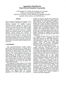
IEEE 802.11 chose an OFDM physical layer for its operation in the 5 GHz band [17] as well as for its extended rate PHY (ERP) amendment for 2.4 GHz operation in order to provide data rates up to 54 Mbit/s. The available bandwidth is divided into 52 sub-carriers from which four are exclusively used as pilots [18]. IEEE 802.11n – aiming at providing even higher throughput of up to 600 Mbit/s – increases the number of sub-carriers from 52 to 56, defines an optional shorter guard period between symbols, and introduces state-of-the-art error coding. Also, the set of available modulation/coding modes, i.e. combining BPSK, QPSK, 16-QAM and 64-QAM with either rate 1/2, 3/4, or 3/4 coding, is increased by adding convolutional coding of rate 5/6. All OFDM-based PHYs utilize link adaptation: for a payload data transmission the data is first convolutional encoded. The resulting data block is transmitted via all available sub-carriers employing the same modulation type on each sub-carrier [18, 19]. The choice of the employed ”mode” is crucial for the performance but not standardized. Instead, the MAC may make usage of, e.g., the radio signal strength indicator (RSSI) level gained during reception of previous packets or adapt the rate depending on the success of a transmission. In addition to increasing the number of sub-carriers, the most significant enhancement of the PHY is the introduction of multiple-antenna capabilities at the transmitter and receiver side. Specifically, these can be distinguished into transmit beamforming, spatial multiplexing and space-time-coding. Transmit beamforming enables a directional shaping of the transmit signal and is mainly used to reduce the impact due to fading at the receiver antenna (while also reducing the interference impact to other cells outside the direction of the current beam). Spatial multiplexing enables the transmission of several different data flows over each of the antennas (without requiring more radio spectrum). Finally, space-time coding uses the additional degree of freedom (provided by the antennas) for improving primarily the error probability (thus, not doubling or tripling the raw data rate as such). Note that in the case of transmit beamforming, the transmitter has to acquire the channel knowledge while in case of spatial multiplexing at least the receiver has to do so (however, if the transmitter also acquires the channel state performance can be even more boosted). Apart from these MIMO capabilities, 802.11n introduces channel bonding–an optional technique to increase the used bandwidth by a factor of two. With respect to the MAC layer, the major improvement is the introduction of frame aggregation. Applying this technique, several payload packets are transmitted during one MAC frame time, i.e. within one channel access in 802.11. Obviously, this improves the efficiency as the overhead for framing and channel access is only spent once. On the other hand frame aggregation is more sensitive to interference as the medium is blocked for a longer time by a single (aggregate) data transmission. The IEEE 802.11n draft suggests two different ways of performing frame aggregation: aggregated MSDU (A-MSDU) and aggregated MPDU (A-MPDU). The first performs the aggregation at the ”top of the MAC” (thus aggregating MAC SDUs without 802.11 specific framing) while the second one performs aggregation ”below the MAC” (thus aggregating several payload packets each with a separate MAC header). Note that even in the case of A-MPDU only packets with an identical destination address can be aggregated. Clearly, A-MSDU reduces the overhead to a minimum at the cost of an increased packet error probability. In
Fig. 1. Physical layer transmission formats possible with 802.11n. Notice that especially due to the multi-antenna capabilities long training fields are required to let the receiver obtain precise enough channel information for MIMO processing.
contrast, A-MPDU enables to check each single packet for an error (by the CRC) while featuring a higher overhead. In addition, A-MPDU enables the usage of block acknowledgments, requesting the retransmission of only a few (or even only one MPDU) out of the set of all transmitted MPDUs. Both frame aggregation types have a maximal data aggregation size: 8 kByte in case of the A-MSDU and 64 kByte in case of the A-MPDU type. The general MAC frame format in IEEE 802.11n is shown in Figure 2. There are two basic changes compared to the 802.11-2007 version of the standard, namely the QoS Control field (2 bytes) and the High Throughput Control (HT Control) field (4 bytes), increasing the overall MAC header by 6 bytes. The HT Control field is responsible for carrying important PHY and MAC information regarding link adaptation, antenna selection and calibration among other information.
Fig. 2. 802.11n MAC frame format.
3
Dynamic OFDM Schemes
In general, dynamic OFDM schemes can be classified into at least two different settings [20]. In a single-user case (point-to-point connection) the transmitter adapts the transmit power and modulation per sub-carrier (depending on the sub-carrier gains) in order to improve/maximize certain metrics like throughput or reliability [10, 11]. In such a setting only frequency diversity is exploited by the transmitter. In contrast, in a multi-user case (a point-to-multi-point communication scenario) the transmitter assigns different (disjoint) sets of sub-carriers to different terminals while also adapting the transmit power and modulation type per sub-carrier which is also referred to as dynamic OFDMA scheme. Let us consider in the following the multi-user scenario. A transmitter holds several packets in its memory, each to be transmitted to a different receiver within its transmission range. Denote the receivers by index j. The packets are to be transmitted via an OFDM link featuring N sub-carriers. A maximum power of Pmax is available for the transmission. Furthermore, the transmitter has the knowledge of the current sub-carrier gains regarding each receiver; (t) denote by hj,n the gain of sub-carrier n between the transmitter and receiver j at the current time t. In this situation it has been shown that applying dynamic frequency division multiplexing (disjoint sets of sub-carriers are assigned to the receivers - each set carries a single packet) outperforms any form of time division multiplexing (each receiver is assigned all sub-carriers for some time span such that the packets are transmitted sequentially) due to exploiting multi-user diversity [12, 21]. However, there are certain requirements for such dynamic OFDMA systems, practically limiting its application range. Prior to the payload transmission the transmitter has to acquire the sub-carrier gains in order to perform the dynamic assignments. Once this information is present at the transmitter, it has to compute the assignments. Finally, the receivers have to be informed of the sub-carrier assignments such that the right sub-carriers can be decoded using the corresponding modulation type. This is often referred to as signaling information and the presence of a signaling system is the third prerequisite for applying dynamic OFDMA.
The complexity of the sub-carrier assignments depends on the objective to be improved as well as on enabling or disabling a variable power assignment per sub-carrier. If the transmit power per sub-carrier can be chosen dynamically, the complexity increases leading to higher run times of the algorithms but also leading to a better objective value obtained [22]. If the transmit power is fixed, each sub-carrier receives the same share of transmit power Pmax /N . (t) (t) Then, the channel gains hj,n directly yield an SNR value γj,n , which immediately yields an modulation type to be (t)
applied (if the sub-carrier is assigned to the corresponding receiver). Hence, hj,n can be converted to a bit value per (t)
sub-carrier/receiver pair bj,n , representing the amount of bits that can be transmitted per symbol on sub-carrier n to (t)
receiver j (referred to as adaptive modulation). Apart from the SNR per sub-carrier/terminal pair, the value of bj,n depends also on the target bit error rate θj per terminal. If a terminal requires a low bit error rate in the physical layer, (t) (t) a higher SNR γj,n is required in order to switch bj,n to higher modulation types. (t)
Given this matrix of bit values bj,n and the set of packets to be transmitted next, a reasonable metric to improve is the amount of time that this dynamic OFDMA burst transmission takes. Assuming all packets to be of equal length, this could be achieved by maximizing the minimum throughput of all considered receivers during the transmission of the burst [21]. In case that the packets are not of equal length, the approach would still be to maximize the minimum throughput, however, the throughput per receiver is scaled according to the ratio between the packet destined for this terminal and the smallest packet to be transmitted. Unfortunately, it is known that this assignment problem is NP-hard [23]. Hence, suboptimal algorithms have to be employed. For a discussion on the assignment scheme used in this paper, refer to Section 5.1.
4
Multi-user Frame Aggregation based on Dynamic OFDMA: 802.11 DYN
The presented approach applies dynamic OFDM to the payload part, i.e. the Data field, of packet transmissions in IEEE 802.11 WLANs using Non-HT and HT-mixed format PPDUs. We refer to our new proposal as 802.11 DYN. It consists of two different modes, a single-user mode and a multi-user mode3 . In this paper we focus on multi-user frame aggregation implemented through dynamic OFDMA - we refer to this as the multi-user mode of 802.11 DYN. We propose the usage of the multi-user mode for down-link data transmissions (from the access point to the stations). As a result, multiple packets can be transmitted in parallel to different stations while the medium is acquired only once. The multi-user mode employs adaptive modulation where per sub-carrier the modulation type is chosen individually (in contrast to link adaptation as used in legacy 802.11a/g/n STAs). Finally, all presented protocol modifications are compatible with existing equipment such that operating a mixture of enhanced stations and ”legacy” stations in one cell is feasible. For supporting the multi-user mode we propose modifications regarding the frame format and the frame exchange sequence. We first describe the new frame format and afterwards discuss the modifications to the frame exchange sequence. Any 802.11 DYN payload frame uses a Non-HT or HT-mixed format PPDU with a slightly modified L-SIG field (cf. Figure 3). The modified frame starts with the usual preambles (L-STF and L-LTF in Figure 1). Afterwards, the first 24 bits of the signal field (L-SIG) are in total compliance to legacy IEEE 802.11a/g/n, with the exception that in the Rate field a different bit sequence is inserted, which is not specified in the standard (causing legacy stations to discard the frame). The bit sequence 1100 identifies the 802.11 DYN frame in the Rate field.. After the Tail field a new element of the L-SIG field is introduced, the Signaling field. This field contains all the information to decode the payload transmission within the Data Field according to 802.11 DYN (either single-user or multi-user case). The precise layout of the signaling field is discussed in detail below. Then dynamic OFDM is applied to the transmission of the payload in the Data Field. For the multi-user case this consists of several pairs of a Signaling field and a corresponding PSDU. These pairs are transmitted on the sub-carrier sets assigned to the respective station. Finally, for each PSDU also a Tail field and potentially some padding bits are transmitted to complete the data frame. The modified L-SIG field of the PLCP frame (including the Signaling field) is transmitted applying BPSK with rate 1/2 convolutional coding. Compared to legacy IEEE 802.11a/g/n systems, the main overhead stems from the Signaling field. We suggest the following format for the Signaling field (cf. Figure 3). Initially, an ID field is transmitted with 2 bit in length, indicating either a multi-user (using a sequence of 11) or a single-user transmission (using 00). Next, a Length field of 9 bit is inserted, which indicates the entire size of the Signaling field. The third field is the Representation field. It is 4 bit long and indicates primarily different types of representing the signaling information (for example, compressed signaling information). Then, the information about the assignments per sub-carrier follow. In case of the multi-user mode, an assignment per sub-carrier is characterized by a station identifier and a modulation identifier. One possible, straight-forward representation of the signaling information has been presented in [25] as fixed signaling size field: Every assignment tuple for each sub-carrier is signaled. Hence, the position of the tuple indicates the sub-carrier this tuple refers to. In 802.11 DYN a station is represented by a 4 bit sequence while a modulation type is represented by 3 bit (leaving some bit combinations for future use). This 3
Both modes have been presented to the IEEE standardization group recently [4, 16]. Also, the single-user mode was presented in [24].
Multiple PSDU
Service + PSDU 1
(1100)
4 bits
RESERVED
LENGTH
PARITY
TAIL
SIGNALING
1 bit
12 bits
1 bit
6 bits
480 bits
...
RATE
Service + PSDU n
BPSK Rate 1/2
TAIL
PAD
TAIL
PAD
TAIL
PAD
ID
Length
2 bits
9 bits
SIGNAL
12 Symbols
20 Symbols
4 bits
Assignments 824 bits
CRC
Tail
16 bits
6 bits
Pad
Dynamic OFDMA
Sub. 1 PREAMBLE
Representation
Sub. 104
Sub. 2
Term. ID Mod ID
Term. ID Mod ID
7 bits
7 bits
....
Term. ID Term. ID Mod ID Coding
...
Term. ID Coding
DATA
7 bits
6 bits
6 bits
Fig. 3. Multi-user mode 802.11 DYN framing – Left figure shows the overall structure of the new PLCP frame – Right figure shows details of the required signaling field of the new PLCP frame.
yields to 7 bit per assignment. Depending on the PLCP frame format, the Signaling field has to contain assignment for 48 sub-carriers in case of 802.11a or 52 sub-carriers per spatial stream in the HT-mixed format of 802.11n. Focusing in the following only on the latter with 2 spatial stream, the total length of the assignments is 728 bits. However, each payload packet is also protected by FEC which has to be indicated to the stations as well. Hence, after the end of the assignments, further tuples are appended consisting of , requiring 6 bit in total. We propose to limit the number of stations included in one multi-user burst to 16, hence the coding assignment field has a maximum length of 96. This leads to a total length of 861 uncoded bits for the signaling field (including the Tail). Note that different assignment representations can reduce this overhead - the employment of these can be indicated in the Representation field. Next, let us discuss the modification of the frame exchange sequence. The new sequence proposed for the multiuser mode is shown in Figure 4. Initially, the access point holds packets for several stations in its cell. Hence, the access point first has to acquire the medium by the standard rules of DCF. After it acquired the medium, it first transmits a CTS-to-self frame (for reasons related to the NAV, as discussed below). Next, the access point has to acquire the channel knowledge. A modified RTS frame is introduced, which carries a polling sequence in it. According to this polling sequence stations answer with a CTS frame which enables the access point to estimate the sub-carrier states using the received frame preamble. The polling order is indicated by transmitting the RTS frame based on the new frame format (as discussed above). The Signaling field of the new frame carries pairs of 48-bit addresses and 4 bit IDs. The sequence of the pairs indicates the sequence with which stations transmit a CTS frame. Furthermore, the pairs also assign 4 bit IDs to each station such that during the following payload transmission stations do not have to be addressed by 48 bits each but by 4 bits. After the last station replied with a CTS frame, the access point starts computing the dynamic OFDMA assignments. Then follows the multi-user payload transmission (we also refer to this as multi-user burst) which employs the new frame format mentioned above. After the multi-user burst transmission, the stations confirm correctly received packets with a legacy ACK frame in the same order already used for channel acquisition. At the end, the access point finishes the multi-user mode frame exchange with a CTS-to-self frame. From DIFS
AP
Channel Acquisition Busy Medium
Backoff
CTS
RTS CTS
CTS
...
CTS
STA SIFS
SIFS
NAV set to the max. time span AP
SIFS or longer Time Span
SIFS
New PLCP Multi−user Frame CTS
CTS ACK
STA
SIFS
ACK
... ACK
SIFS
Assignment Generation NAV reset to the precise end
Fig. 4. Transmission sequence of the new 802.11 DYN multi-user mode. In order to set the NAV correctly, a slightly modified transmission sequence is required.
the description above, several open issues arise. First of all, the management of the NAV is more complicated for the dynamic scheme: After winning the channel during the contention phase, the access point does not know how long the packet transmission will take due to the still unknown sub-carrier states. Hence, up to the payload transmission, it has to announce a pessimistic estimate of the NAV setting, e.g., reserving the channel for the time span needed to convey all scheduled packets if for all stations only BPSK with rate 1/2 encoding can be used. Once the sub-carrier assignment are computed, the exact NAV can be distributed in the cell. However, as the initial RTS frame and the
payload frame are transmitted with the new PLCP frame format, legacy stations have to be informed by a different way of the pessimistic NAV estimate and the updated NAV. This is the reason for starting the whole sequence with a CTS-to-self frame. The CTS frames, coming back from the stations after polling them, announce this pessimistic NAV value within the entire transmission range. After the access point acquired the channel knowledge, it can announce the correct NAV value in its multi-user burst frame. However, this is not decoded by legacy stations due to its new frame format. Hence, after the ACK frames reset the NAV value in the transmission range, the access point has to ensure by a final CTS-to-self frame (carrying the correct NAV setting) that all stations reset their NAV. Finally, the issue has to be resolved how stations (and APs) identify that their communication peer supports 802.11 DYN. For the infrastructure mode, we suggest the following solution. APs announce their support of 802.11 DYN in a special capability field of the Beacon. If a station receives such a Beacon, it will trigger 802.11 DYN the first time it transmits a data frame to the AP. Then the AP is informed of the 802.11 DYN support by the station and stores this information in a list of currently associated stations.
5
Performance Evaluation
5.1 Simulation Model The following system model is assumed for simulations: Within a single WLAN cell there are J stations and one access point located. Packets arrive either at the access point for down-link transmission or at the stations for up-link transmission. Per simulation run, all payload packets have a fixed size of ς bits. PHY model The maximum transmit power equals Pmax = 10 mW. The bandwidth, the number of sub-carriers, the symbol duration and the guard interval are all chosen in accordance to IEEE 802.11n (see Section 2). We assume in the following the application of 2 by 2 MIMO spatial multiplexing with MMSE reception to separate the spatial streams. In order to generate the MIMO channel matrix the 802.11n task group published a MATLAB module to generate traces of MIMO channel states [26, 27]. We use this tool to generate the channel matrix. We consider channel type ’E’ representing a large office environment with a certain path loss model and a fading characterized by a delay spread of 100ns [27]. In general, the sub-carrier gains are assumed to be stable during the transmission of a PLCP payload frame – either in the legacy mode or in the 802.11 DYN case. The noise power σ 2 is computed at an average temperature of 20◦ C over the bandwidth of one sub-carrier (312.5 kHz). Packet Error Rate Model Clearly, we require a detailed packet error model for the link layer, which takes the fading and modulation setting of individual OFDM sub-carriers into account. Packet error rate investigations for OFDM transmission over a frequency-selective channel can be found for example in [28]. We follow a similar approach relying on an upper bound for the packet error probability, which takes the average bit error probability (of the modulation types per sub-carrier) as input. Note that in case of 802.11 DYN (either the single-user or multi-user mode) the system can control the bit error probability θj by setting the respective switching levels of the adaptive modulation (at which SNR points the modulation should be changed to a higher or lower one). As a detailed presentation of the packet error rate model has already been given, we refer the interested reader to [24]. Simulation Methodology All results are generated with OPNETmodeler Version 14.0.A-PL-5. Modifications of standard models required to support 802.11 DYN are with regard to the OPNET model library as of September 2007 [29]. For the simulation of the 802.11 system, we generally follow the standard as close as possible. We only consider long preambles. All non-payload frames of 802.11 DYN are transmitted in base mode (BPSK with rate 1/2 encoder) and are always received correctly (i.e. only for payload frames we generate an instantaneous packet error rate and evaluate that). For all our simulations we vary the distance between access point and stations (hence, we vary the average SNR) as well as the number of stations present in the cell. For a single simulation run we do not consider mobility. Also, for a single simulation run all stations have the same distance to the access point and therefore the same average SNR due to path loss. For the saturation mode we transmit about 5000 packets per run and obtain average performance results from that. The fading components of the OFDM sub-carrier channel gains are randomly regenerated at each payload packet transmission and therefore the error behavior for two sequentially transmitted packets can be assumed to be statistically independent. However, for all packet transmissions correlation of the fading in frequency is fully taken into account. The 99% confidence levels of all our results are very high and are not shown in the following graphs due to their small size. Comparison Schemes and Metrics We are interested in the saturation mode throughput of 802.11 DYN versus legacy 802.11n. For this specific investigation, we assume in addition to the above mentioned model that the access point always holds a packet for each station in the cell. Stations do not have any data to send - we are only interested in the down-link performance. Hence, no collisions occur. The chosen performance metric is link layer goodput in bit/s. We compare two different schemes:
– 802.11n : The access point serves one station after the other one (in a round robin fashion) using 802.11n. Optionally, frame aggregation can be activated. In that case the AP transmits multiple packets within a single channel access to the corresponding station (note that the AP always has enough packets queued in order to fill any depth of frame aggregation). The depth of the frame aggregation is key to the observed performance. We comment explicitly below on the chosen depths. Furthermore, we consider the performance of each transmission mode (combination of modulation type and forward error correction) separately over the full SNR range. – 802.11 DYN Multi-user mode: The multi-user mode enables the transmission of several packets simultaneously to different stations by applying multi-user frame aggregation based on dynamic OFDMA. The PHY applies now adaptive modulation with respect to a pre-specified target bit error probability θj per station. Again, the setting of this error probability has a significant impact on the system performance, as demonstrated by us for the 802.11 DYN single-user mode on top of 802.11a [24]. In this section, we only provide results for the optimum setting of θj . We consider up to eight stations in the cell for the saturation mode investigations. This keeps transmission times reasonably short even if large packet sizes are assumed. Notice that in addition to multi-user frame aggregation, the access point can also apply frame aggregation per station. One particular important issue in case of the multi-user mode is how sub-carriers are assigned to stations (in general, how the scheduling of packets to sub-carriers works). The focus of our work is not on optimal scheduling schemes and resource assignment algorithms. Hence, we pick a straightforward approach for assigning sub-carriers to packets: Each station receives the same amount of sub-carriers. If four stations are considered during the next down-link transmission, each station receives 26 sub-carriers. Given this fixed sub-carrier allocation, a simple dynamic algorithm is employed to pick the specific sub-carriers assigned to each station [30]. Basically, it considers one station after the other and assigns the preallocated number of “best” sub-carriers to the corresponding station from the set of remaining sub-carriers. In order to maintain fairness, the order of picking sub-carriers for stations is shifted on a per-down-link transmission base. 5.2 Results We consider four different parameters for our down-link saturation mode evaluation: average SNR (i.e. distance between the access point and stations), packet size ς, frame aggregation depth and number of stations present in the cell. In the following we first discuss the results related to a small packet size (equaling roughly VoIP packets), then we consider the results for large packet sizes. Before starting this discussion, recall that it is generally known that saturation mode performance in 802.11 systems depends heavily on the considered packet size and the large the considered packet is, the less does the MAC overhead influence the performance results. Small Packets of 234 Byte For the following discussion notice that we assume a maximum (single station) frame aggregation of 4 packets. This is motivated by the fact that such small packets are assumed to stem from a VoIP flow. As such flows are well known to be delay sensitive, we set the maximum frame aggregation depth to four (considering a G.711 voice encoder at a rate of 64 kbps, a VoIP packet plus RTP, UDP and IP header – 200 Byte – is generated every 20 ms). In the first scenario we consider four stations to be present in the cell. In case of 802.11n always four packets are aggregated (for the same station) while in case of 802.11 DYN four packets four different stations are multiplexed. Hence, per station 802.11 DYN does not apply frame aggregation initially. In this first scenario 802.11n also employs the RTS/CTS handshake prior to transmission of the aggregated frame due to the large payload size. In Figure 5, the corresponding average goodput per station is presented for an increasing SNR. Notice that the figure shows eight different curves for 802.11n as we show initially the performance results of all eight PHY modes (in all other graphs we will only show the upper envelope of the PHY modes). We observe a significant performance gain in the case of 802.11 DYN at low SNR values, however from 10 dB on the legacy modes outperform 802.11 DYN clearly. At very high SNR values, the legacy scheme achieves a goodput which is roughly 150% higher than the one of 802.11 DYN. What is the reason for this performance behavior? First notice that for small packets the raw PHY performance plays a smaller role as a lot of time is spent for resolving medium contention at the MAC. In fact, the faster the PHY transmits the payload (at high SNR values, for example) the more important gets the overhead due to RTS/CTS handshake, ACK frames and framing. From the above sections it is clear that 802.11 DYN is related to a large additional overhead in order to implement dynamic OFDMA (channel acquisition, signaling of assignments, NAV management). From Figure 6 we see that 802.11 DYN features a much lower PER rate while providing a higher spectral efficiency. Especially the low PER leads to the observed performance improvement for small SNR values. However, as packet error rates improve in case of 802.11n, the protocol overhead becomes much more an issue and so 802.11n outperforms 802.11 DYN. Notice in general the superior performance of 802.11 DYN regarding the PHY efficiency in the left graph of Figure 6. The performance of 802.11 DYN increases continuously along the whole SNR range delivering significant gains (100-300%) compared to IEEE 802.11n. Apart from the more precise modulation and coding selection, 802.11 DYN also benefits from multi-user diversity, which helps to further increase the physical layer efficiency. Notice that these performance improvements are coupled with a much lower packet error rate (right
4 3.5 3 2.5 2
Goodput [Mbps]
1.5 1 0.5 0 6
8
10 12 14 16 18 20 22 24 26 28 30 32 34 36 38 40
SNR [dB]
Dynamic OFDMA
Mode 5 Mode 6 Mode 7 Mode 8
Mode 1 Mode 2 Mode 3 Mode 4
Fig. 5. Average goodput per terminal comparison between 802.11 DYN and selected PHY modes of 802.11n (showing also the envelope of maximum performance (blue curve)) for various different SNR levels. The packet size is set to 234 Byte. J = 4 stations are present in the cell. The legacy scheme performs the aggregation of 4 MPDUs, while 802.11 DYN does not make usage of this technique.
graph in Figure 6). Recall that the packet error probability is controlled in 802.11 DYN due to exploiting channel state information and adapting modulation types with respect to target bit error probability. 1
4.5 0.1 4 3.5 0.01
3 2.5
Packet Error Rate
PHY Efficiency [bits/Sub−carrier/Symbol]
5
2 1.5 1 0.5
0.001
0.0001 6
0 6
8
10 12 14 16 18 20 22 24 26 28 30 32 34 36 38 40
8
10 12 14 16 18 20 22 24 26 28 30 32
SNR [dB]
Dynamic OFDMA
IEEE 802.11n
34 36 38 40
SNR [dB]
Dynamic OFDMA
Mode 1 Mode 2 Mode 3 Mode 4
Mode 5 Mode 6 Mode 7 Mode 8
Fig. 6. Performance comparison of 802.11n and 802.11 DYN for small packets and four stations in the cell. Left figure Average PHY efficiency per subcarrier and symbol. Right figure Average packet error probability per station.
Even though 802.11 DYN has a very efficient behavior at the physical layer, the overhead caused by the protocol may strongly reduce the achieved gain, as seen in Figure 5. Hence, in Figure 7 we activate now single station frame aggregation in case of 802.11 DYN, allowing it a maximum aggregation depth of 4. In this case, 802.11 DYN transmits 16 packets per successful medium access. This leads to a better MAC efficiency of 802.11 DYN and reduces the impact of the protocol’s overhead. When frame aggregation is deactivated a maximal goodput per user of about 1.5 Mbps can be obtained by 802.11 DYN. When 2 MPDUs are aggregated the maximal goodput reaches 3 Mbps and it slightly rises above 5 Mbps when the aggregation of 4 MPDUs is performed. Again, IEEE 802.11n aggregates 4 MPDUs, but in contrast to Figure 5 only the envelope of the best performing legacy mode at any SNR is plotted. In this case, the results presented consider both, the activation and deactivation of the RTS/CTS frame exchange. Notice that the results corresponding to the deactivation of RTS/CTS handshake have to be seen as upper bound rather as we assume that the access point always chooses the optimal PHY mode. Without a initial RTS/CTS handshake this can not be always assumed in reality. In Figure 5 it can be observed that the higher the aggregation depth used for 802.11 DYN, the larger the range where it outperforms the legacy scheme. In the comparison there is always a cross-over point, from which one IEEE 802.11n outperforms 802.11 DYN. Next, consider the right graph of Figure 7. Here we consider the same scenario but increase the number of stations in the cell to J = 8. Since the total number of aggregated packets is considerably higher in the case of 802.11 DYN, its MAC efficiency is increased as the overheads
3
5
2.5
4
2
3
1.5
2
1
Goodput [Mbps]
Goodput [Mbps]
6
1
0 6
8
0.5
0 6
10 12 14 16 18 20 22 24 26 28 30 32 34 36 38 40
8
10 12 14 16 18 20 22 24 26 28 30 32 34 36 38 40
SNR [dB]
SNR [dB]
Dynamic OFDMA: FA1 FA2 FA4
Dynamic OFDMA:
IEEE 802.11n + FA4:
FA1 FA2 FA4
With RTS/CTS Without RTS/CTS
IEEE 802.11n + FA4: With RTS/CTS Without RTS/CTS
Fig. 7. Comparison of the average goodput per station of 802.11 DYN 802.11n. The packet size is set to 234 Byte. Left figureJ = 4 stations are present in the cell. 802.11 DYN applies a frame aggregation of 1, 2 and 4 packets, while 802.11n aggregates always 4 packets. Also, 802.11n results are given depending on the usage of RTS/CTS frame exchange. Right figure Same comparison with J = 8 stations in the cell.
impact is reduced. Taking IEEE 802.11n without RTS/CTS as reference, 802.11 DYN without frame aggregation is outperformed by the legacy scheme from 10 dB on. When 802.11 DYN aggregates 2 MPDUs the crossing-point is shifted to 17 dB and when 4 MPDUs are aggregated 802.11 DYN performs better over the whole SNR range plotted. Notice that the increase in PHY efficiency due to multi-user diversity is modest - the major performance improvement stems from a better MAC efficiency in case of a higher frame aggregation depth. Large Packets of Size 1536 Byte Next, we increase the packet size to 1536 Byte, corresponding to large IP packets. Assuming the packets to belong to web traffic or data transfers, delay is less an constraint (compared to VoIP) allowing a larger aggregation depth. However, aggregation depth is still limited by the time-selective behavior of the channel. This time-selectivity is measured for example by the coherence time. Coherence time is defined as the amount of time during which the autocorrelation function of the channels random gain is greater than a certain value (for example 0.9). Hence, coherence time can be assumed to be the period during which the channel is roughly constant. In the following we will limit the aggregation depth by the coherence time of the channel. Regarding a system operating at the 5.2 GHz band and considering that all the objects in the environment do not move faster than 1 m/s (pedestrian velocity), the coherence time is about 12.5 ms [31]. When analyzing if the coherence time is exceeded, for simplification purposes, the time needed to transmit packet headers and control frames is not considered. Since the data size is considerably large, this simplification is negligible. Furthermore, we only do the the calculation for the worst considered SNR (of about 6 dB). When 4 stations are present in the cell, 802.11 DYN can aggregate a maximum of 7 large MPDUs per station (leading to 28 packets transmitted in total), while IEEE 802.11n is able to aggregate 12 such packets. In case of J = 8 stations present in the cell, 802.11 DYN can aggregate a maximum of 3 packets per station while 802.11n aggregates again at most 12 packets per station. 25
12
20
10
8 15 6
Goodput [Mbps]
Goodput [Mbps]
10
5
0 6
8
10 12 14 16 18 20 22 24 26 28 30 32 34 36 38 40
SNR [dB]
4
2 0 6
8
10 12 14 16 18 20 22 24 26 28 30 32 34 36 38 40
SNR [dB] Dynamic FA 1 OFDMA FA 4 FA 7
IEEE 802.11n
FA 4 FA 8 FA 12
Dynamic FA 1 OFDMA FA 2 FA 3
IEEE 802.11n
FA 4 FA 8 FA 12
Fig. 8. Comparison of the average goodput per station for 802.11 DYN and 802.11n (with RTS/CTS handshake) for various different SNR levels. The packet size is set to 1570 Byte. Left figure J = 4 stations are present in the cell. 802.11 DYN applies a frame aggregation of 1, 4 and 7 packets, while 802.11n aggregates 4, 8 and 12 packets. Right figure J = 8 stations are present in the cell. 802.11 DYN applies a frame aggregation of 1, 2 and 3 packets, while 802.11n aggregates 4, 8 and 12 packets.
Approach SNR (dB) PHY Efficiency Aggregated MPDUs Goodput (Mbps) 802.11n 12.5 0.5 12 2.40 802.11 DYN 12.5 2.34 15 8.83 802.11n 20.5 1.5 38 6.28 802.11 DYN 20.5 4.46 28 21.27 802.11n 27.7 3 77 11.25 802.11 DYN 27.7 4.91 31 24.45 Table 1. IEEE 802.11n and 802.11 DYN goodput performance for the highest frame aggregation depth allowed at different SNR points.
The goodput results that correspond to these aggregation depths are shown in Figure 8. The left figure shows the results for j = 4 stations, while the right figure shows the results for J = 8 stations in the cell. All 802.11n curves are based on RTS/CTS handshake. Comparing the best performing curves of each transmission scheme, the range where 802.11 DYN outperforms IEEE 802.11n goes up to 36 dB for J = 4 stations in the cell. For all SNR points below 36 dB a huge gain is observed sometimes about 200-300%. Frame aggregation increases significantly the performance of both systems, especially at medium and high SNR values. Notice that in IEEE 802.11n the use of frame aggregation starts paying off from an SNR of 18 dBs on. Prior to that point the system’s performance does not vary significantly for different aggregation depths. In the low SNR range, where the PHY efficiency is considerably small, the transmission of the payload packet takes much more time than the time needed to transmit protocol’s overhead and control frames. If control information is negligible, increasing the data packet size by a factor χ approximately increases the whole transmission time also by a factor χ. Frame aggregation is able to increase the MAC efficiency of the protocol significantly only when the time required for payload transmission is roughly in the same order as the duration for transmitting the control information. Since 802.11 DYN introduces much more overhead than the legacy scheme, the gain that the system can obtain by using this technique is correspondingly higher. Similar observations regarding the performance difference of 802.11 DYN and 802.11n can be found for J = 8 stations in the cell (right graph of Figure 8). Notice that the limitations on the frame aggregation depth – as applied in Figure 8 – do not hold for larger SNR values. Hence, we pick three different SNR values at 12.5, 20.5 and 27.7 dB, recalculate the corresponding frame aggregation depths and perform simulations with these values. Table 1 shows the average goodput per station that can be achieved by 802.11 DYN and IEEE 802.11n when the maximal frame aggregation depth is applied for different SNR points. This more sensible comparison of the two schemes reveals that, assuming that enough packets are available in the queues, 802.11 DYN delivers a much higher goodput performance than IEEE 802.11n for medium and large SNR values than observed from Figure 8. The major reason for this is that 802.11 DYN achieves a much better PHY efficiency for larger SNR values and can therefore aggregate more packets than 802.11n. This reduces the impact of the additional overhead to a minimum.
6
Conclusions
In this paper we have presented a novel protocol which allows multi-user frame aggregation in 802.11 WLANs. The approach is coupled with channel-dependent (i.e. dynamic) OFDMA resource assignments which exploits multiuser diversity. This combination promises an increase in PHY efficiency as well as in MAC efficiency. On the other hand, significant additional overhead is required to guarantee backward compatibility and enable dynamic OFDMA resource assignments. In comparison to 802.11n we show that our novel approach outperforms state-of-the-art WLAN technology whenever payload packet sizes or frame aggregation depths are large. Then the proposed protocol enhancement benefits from the improvement in PHY efficiency while the required overhead is less important. However, if only few bytes are to be transmitted, the considered multi-user approach is significantly outperformed by 802.11n. We believe that additional research should focus on ways to reduce the associated overhead with multi-user frame aggregation via dynamic OFDMA to improve its performance in case of smaller payload packet sizes.
Bibliography
[1] IEEE 802.11n – Enhancementsw for Higher Throughput, Amendment 4 to IEEE 802 26 27 28 Part 11: Wireless LAN Medium Access Control (MAC) and Physical Layer (PHY) specifications, IEEE 802.11n/D2.04, June 29 2007. [2] e. a. Matt Smith, “Proposal for par and 5 criteria for very high throughput (vht) sg for 60 ghz,” IEEE 802.11 VHT SG Very High Throughput Study Group, Jacksonville, FL, USA, doc. 08/223, May 2008. [3] e. a. Marc de Courville, “Proposal for par and 5 criteria for very high throughput (vht) sg for below 6 ghz operation,” IEEE 802.11 VHT SG Very High Throughput Study Group, Jacksonville, FL, USA, doc. 08/609, May 2008. [4] J. Gross, M. Emmelmann, O. Punal, and A. Wolisz, “Dynamic multi-user ofdm for 802.11 systems,” IEEE 802.11 VHT SG Very High Throughput Study Group, San Francisco, CA, USA, doc. 07/2062, July 2007. [5] ——, “Performance comparison of dynamic ofdm with 802.11n,” IEEE 802.11 VHT SG Very High Throughput Study Group, Atlanta, GA, USA, doc. 07/2860, November 2007. [6] M. de Courville, M. Kamoun, A. Robert, J. Gosteau, R. Fracchia, and S. Gault, “Another resource to exploit: multi-user diversity,” IEEE 802.11 VHT SG Very High Throughput Study Group, San Francisco, CA, USA, doc. 07/2187, July 2007. [7] A. Czylwik, “Adaptive OFDM for wideband radio channels,” in Proc. of the Global Telecommunications Conference, 1996. [8] R. Gruenheid and H. Rohling, “Performance comparison of different multiple access schemes for the downlink of an OFDM communication system,” in Proc. of VTC’97, May 1997. [9] T. Keller and L. Hanzo, “Adaptive multicarrier modulation: A convenient framework for time-frequency processing in wireless communications,” vol. 88, no. 5, pp. 611–640, May 2000. [10] J. Campello, “Practical bit loading for DMT,” in Proc. IEEE Int. Conference on Communications (ICC), 1999. [11] L. Piazzo, “Fast optimal bit-loading algorithm for adaptive ofdm systems,” University of Rome, Tech. Rep. 002-04-03, 2003. [12] C. Wong, R. Cheng, K. Letaief, and R. Murch, “Multiuser OFDM with adaptive subcarrier, bit and power allocation,” vol. 17, no. 10, pp. 1747–1758, 1999. [13] D. Kivanc, G. Li, and H. Liu, “Computationally efficient bandwidth allocation and power control for OFDMA,” vol. 2, no. 6, pp. 1150–1158, 2003. [14] A. Barreto and S. Furrer, “Adaptive Bit Loading for Wireless OFDM Systems,” in Proc. IEEE Int. Symposium on Personal, Indoor and Mobile Radio Communications (PIMRC), 2001. [15] S. Valentin, T. Freitag, and H. Karl, “Integrating multiuser dynamic ofdma into ieee 802.11 wlans - llc/mac extensions and system performance,” May 2008. [16] J. Gross, M. Emmelmann, O. Punal, and A. Wolisz, “Dynamic point-to-point ofdma adaptation for ieee 802.11a/g systems,” IEEE 802.11 WNG SC Wireless Next Generation Standing Committee, Montreal, Canada, doc. 11-07/720, May 14 – 18 2007. [17] IEEE 802.11a – High-speed Physical Layer in the 5 GHz Band, Amandment 1 to 802.11, IEEE Std. 802.11a, 2000. [Online]. Available: http://standards.ieee.org/getieee802/download/802.11a-1999.pdf [18] IEEE 802.11 – Wireless LAN Medium Access Control (MAC) and Physical Layer (PHY) Specifications, IEEE Std. 802.112007, June 12 2007. [19] IEEE 802.11n – Enhancements for Higher Throughput, Amendment 4 to IEEE 802.11 Part 11: Wireless LAN Medium Access Control (MAC) and Physical Layer (PHY) specifications, IEEE 802.11n/D3.11, December 1 2007. [20] M. Bohge, J. Gross, M. Meyer, and A. Wolisz, “Dynamic resource allocation in OFDM systems: An overview of cross-layer optimization principles and techniques,” vol. 21, no. 1, pp. 53–59, 2007. [21] W. Rhee and J. Cioffi, “Increase in capacity of multiuser OFDM system using dynamic subchannel allocation,” in Proc. Vehicular Technology Conference (VTC), May 2000. [22] M. Bohge, J. Gross, and A. Wolisz, “The Potential of Dynamic Power and Sub-carrier Assignments in Multi-User OFDMFDMA Cells,” in Proc. of IEEE Globecom, November 2005. [23] J. Gross and M. Bohge, “Dynamic mechanisms in ofdm wireless systems: A survey on mathematical and system engineering contributions,” Telecommunication Networks Group, Technische Universit¨at Berlin, Tech. Rep. TKN-06-001, May 2006. [24] J. Gross, M. Emmelmann, O. Punal, and A. Wolisz, “Dynamic single-user ofdm adaptation for ieee 802.11 systems,” in Proc. ACM/IEEE International Symposium on Modeling, Analysis and Simulation of Wireless and Mobile Systems (MSWIM 2007), Chania, Crete Island, Oct. 2007, pp. 124–132. [25] J. Gross, I. Paoluzzi, H. Karl, and A. Wolisz, “Throughput study for a dynamic OFDM-FDMA system with inband signaling,” in Proc. Vehicular Technology Conference (VTC Spring), May 2004. [26] L. Schumacher, “Wlan mimo channel matlab program,” Tech. Rep. [Online]. Available: http://www.info.fundp.ac.be/∼lsc/ Research/IEEE 80211 HTSG CMSC/distribution terms.html [27] V. Erceg, L. Schumacher, P. Kyritsi, A. Molisch, D. S. Baum, A. Y. Gorokhov, C. Oestges, Q. Li, K. Yu, N. Tal, N. Bas Dijkstra, A. Jagannatham, C. Lanzl, V. J. Rhodes, J. Medbo, D. Michelson, and M. Webster, TGn Channel Models, IEEE 802.11 TGn High Throughput Task Group doc. 03/940, May 2004. [28] O. Awoniyi and F. Tobagi, “Packet Error Rate in OFDM-based Wireless LANs Operating in Frequency Selective Channels,” in Proc. IEEE INFOCOM, April 2006.
[29] “Opnet modeler wireless suite,” 2007. [Online]. Available: http://www.opnet.com/solutions/network rd/modeler wireless. html [30] J. Gross, H. Karl, F. Fitzek, and A. Wolisz, “Comparison of heuristic and optimal subcarrier assignment algorithms,” in Proc. Int. Conference on Wireless Networks (ICWN), June 2003. [31] A. Aguiar and J. Gross, “Wireless channel models,” Telecommunication Networks Group, Technische Universit¨at Berlin, Tech. Rep. TKN-03-007, April 2003.