Multipurpose Controller Based on a FPGA with EPICS Integration∗ P. Echevarria, I. Arredondo, D. Belver, M. del Campo, N. Garmendia, H. Hassanzadegan, L. Muguira, ESS-Bilbao, Spain V. Etxebarria, J. Jugo, University of the Basque Country, Leioa, Spain Abstract In this work a multipurpose configurable control system is presented. This controller is based on a high performance FPGA for a fast control, connected to a Host PC which works as an EPICS server to allow a distributed control. The communication between both parts is made by a register bank implemented in the FPGA and which is accessible by the Host PC by means of a Compact PCI bus. The initialization values, the numeric representation of the digital signals and the application specific parameters are configured by XML files. A MySQL database is ready and integrated in EPICS via RDB and CSS. This control scheme has been prototyped for two applications: Low Level RF and Beam Position Monitoring. The former contains three digital loops to control the amplitude and phase of the RF supply and the geometry of the cavity. The latter processes the information from four capacitive buttons to calculate the position of the beam. In both systems, the necessary parameters for the digital processing of the acquired signals (using fast ADCs) and intermediate calculations are stored in the register bank connected to the cPCI bus. These systems are being developed for the ESS-Bilbao facility which will be built in Bilbao, Spain.
1
INTRODUCTION
In a particle accelerator the beam diagnostics and the design of control systems is a key issue for its correct operation. In this kind of facilities a real-time control is needed which implies a fast signal acquisition and a fast calculation rate. Normally, this control is made locally and when all the parameters are tuned, it works with a minimum operator involvement. Nevertheless, it is needed to monitor this parameters to avoid a malfunction. This monitoring is not made locally but from a Control Room instead. Therefore, the diagnostic and control system is provided of two functionalities: • A local real time control which demands high performance hardware. • A distributed networked control to handle a high number of signals which requires a proper information management. This work details a solution based in a high performance digital board which implements the real-time control and a control PC (Host PC) which implements an Experimental ∗
[email protected]
Physics and Industrial Control System (EPICS [1]) server using JavaIOC [2] for the networked control. The system structure and its configuration via XML files turns it into a multipurpose controller.
2
SYSTEM DESCRIPTION
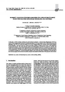
The implemented local system is formed by two fundamental elements: the VHS-ADC board of Lyrtech company [3] and a Host PC where the Hardware Controller (HC) is installed. As it is depicted in figure 1, the instrument under control is connected to the Lyrtech board which is linked to the Host PC via a cPCI port. In the Lyrtech board, which is based on a FPGA, the real-time algorithm is implemented, while the Host PC reads and writes different control parameters to the FPGA, making possible a distributed control. This networked control can be done using the Host PC as an EPICS IOC to communicate with a local area network. The HC implementation, based on Java, consists of several threads coordinated to make the write and read operations and it is configured using a XML file, where some information about each parameter is detailed: name, number of bits, precision, the register where it will be stored, if it is a write or read register and its initial value. This file will contain as many structures as necessary depending on the specific application. For the configuration of the EPICS server, it is also needed a database (DB) described as well using XML. As future work the EPICS database will be included in the HC configuration file to facilitate the use of the controller.
3
HARDWARE DESCRIPTION
The hardware of the proposed control system can be clearly separated into two parts: a fast processing board and a control PC. The processing board has a high performance FPGA with high frequency Analog to Digital converters (ADC). The Host PC is used as an interface between the operator and the processing board (local control) and as an EPICS server (distributed control). Below, both parts are described in detail.
The digital processing is done by a Lyrtech VHS-ADC board. The core of this board is a Virtex-4 of Xilinx [4] with 152000 logic cells and a maximum frequency of 500MHz, connected to a ADC converter with 8 channels of 14 bits which can operate at a frequency of 105MHz.
PC Server Lyrtech VHS ADC
Instrument Out
AD
In
DA
PC Client Put
Read
LAN
HC
FPGA cPCI
EPICS IOC
EPICS Client
Get
Write
Bitstream
DB
XML Conf. Configuration Files
Figure 1: General scheme. Host PC cPCI
Register bank
Control algorithm
DAC
Configuration parameters
ADC
The high parallelism offered by the FPGA when implementing different algorithms, with the high sampling rate of the converters, make this board a good choice to make a high performance control. Moreover, the VHS-ADC contains several peripherals that expand the processing capacity of the board, and the communication with other devices, like a 128MB SDRAM memory, several clock sources, an expansion connector (which allows another ADC module, a DAC module or a 2GB SDRAM memory) and several communication channels. Regarding the design of control algorithms, the use of Xilinx software and Intellectual Property (IP) blocks make possible all the typical options in these kind of solutions. For a purely hardware design, the development environment ISE allow the design by hardware description languages (VHDL or Verilog) or by schematics. The availability of the MicroBlaze soft-core allows programming part of the FPGA as a microprocessor, which makes possible mixed hardware-software algorithms. For this mixed design, the Embedded Development Kit (EDK) can be used to integrate the hardware designs made with ISE with software programs running in the MicroBlaze. In addition to these low level design tools, Xilinx System Generator allows the use of Matlab Simulink which eases the design of the system and make possible carrying out Hardware-inthe-Loop simulations. The utilization in the design of the different board peripherals is simplified by a “by default” FPGA design provided by Lyrtech. This “by default” design offers several resources for, among others, communicating the FPGA with the Host PC. One of these resources is a bank of 12 registers of 32 bits for writing and reading implemented in the FPGA and accessible from the CPI bus. In this way, this register bank turns into a small shared storage block with a fast and simple access. The main issue of this register bank is the relative small number of registers, but it can be easily resolved by a multiplexing. The least significant part of one register is used to store a 16-bit data, while n bits of the most significant part, with 1 < n ≤ 15, are used for the address of a new expanded register bank in the FPGA. The most significant bit is used to determine if it is a writing or reading operation. Therefore, a expanded register bank with 2n 16-bit registers is implemented.
FPGA
Figura 2: General scheme of communication between the control algorithm and the Host PC. The proposed solution to make a multipurpose controller is based on this register bank. The different parameters needed for the control algorithm are stored in these registers, in such a way that they are accessible from the Host PC (figure 2).
The Host PC is connected to the Lyrtech board by the cPCI bus. By this connection, several board configuration operations can be made: ADC configuration (clock source, trigger signal, etc), program the FPGA with a bitstream file, write and read the SDRAM and FLASH memories and write and read the register bank. Lyrtech provides a simple control software which permits these kind of operations in an intuitive way, however, it suffers from a lack of flexibility for, for example, manipulating the information to send or receive from the FPGA.
One option to partially resolve this lack of flexibility is to use a Hardware-in-the-Loop cosimulation, where the system behavior can be analyzed using Matlab Simulink. The major drawback of this cosimulation is the need of programming specific cosimulation blocks in the FPGA, which increases the number of the needed logic blocks and slows down the communication through the cPCI bus. Moreover, Xilinx, Lyrtech and Matlab software must be installed in the Host PC, which requires certain calculation power and the subsequent licenses. It is a very good solution to check and debug the control algorithm but not for its final implementation.
The solution taken in this work is based on the build of custom control software using the Lyrtech API. From this API, written in C, a Dynamic Link Library has been generated and it allows the utilization of the Lyrtech communication and configuration functions in a custom Java application using Java Native Access. Moreover, to get the flexibility which gives the command shell, Jython commands have been developed combining Java and Dynamic Link libraries.
4
DISTRIBUTED NETWORKED CONTROL
The distributed control is performed via EPICS. EPICS, from Experimental Physics and Industrial Control System, is a set of Open Source software tools, libraries and applications developed collaboratively and used worldwide to create distributed soft real-time control systems for scientific instruments such as a particle accelerators, telescopes and other large scientific experiments [1]. To implement EPICS in the system, JavaIOC is chosen. This packages gives some of the EPICS Base (which is programmed in C) capabilities, but using Java. Its most generic function is to create an IOC (Input/Output Controller) to connect to EPICS net, but it also can be utilized to generate EPICS clients. In this multipurpose controller the distributed control through EPICS is composed by two threads. On one hand, one thread responsible for setting up the IOC and on the other, the second thread which communicates the input/output registers with the IOC. This thread, uses JavaIOC specific functions to perform the communication. Concretely, the refresh of the process variables (PV) is carried out with an asynchronous caput, while the data reading is done by a asynchronous caget. This reading solution is not optimal and the team is working in the implementation of one monitor which will take the value only when the reading value changes. In order to avoid problems between local and distributed controls, if one is connected the other is disconnected and vice versa. To create the IOC it is necessary a Data Base (DB) with the specification (type, sampling time, alarms,...) of each signal. As it has been mentioned above, nowadays the configuration file does not include the EPICS DB, but it is expected that it will be able to create it automatically. EPICS is capable of performing calculations using the DB’s definition, however, in the chosen implementation, the required operations are worked out by the Hardware Controller. In relation to the EPICS client, there is not restriction in its implementation. It depends on the application and on the requirements of each specific facility. The tests and GUIs designed by ESS-Bilbao have been carried out with Control System Studio (CSS) created by the Spallation Neutron Source (SNS), Oak Ridge, Tennessee [5]. For the data archiving two possibilities are going to be
tested. The EPICS standard archiving (RDB) and a Java based archiving in the HC. All of them will be based on MySQL database. Nowadays the MySQL database is ready and integrated in EPICS via RDB and CSS.
5
APPLICATIONS
The main idea of this controller which is based on the Lyrtech VHS_ADC is to be very versatile, due to the high number of precise inputs-outputs and it computing quickness. Also it has the possibility of connection to a central network. This characteristics make this controller a good alternative in large scientific facilities and in devices with fast computing requirements. In ESS-Bilbao this controller is expected to be used in the Beam Position Monitors (BPM) and in the Low Level RF (LLRF).
For the BPMs it is being currently proved in a test-stand with four buttons (manufactured by Kyocera) and an analogical front-end to condition the signal for be acquired by the Lyrtech VHS-ADC. Inside the FPGA it is implemented the treatment of the signal measured by the buttons (cordic algorithm). Inside the HC there are: The ∆/Σ algorithm [6] and the linearization (non-linear correction to measure properly no centered beams). It is expected to handle at least two BPMs with this solution.
The ESS-Bilbao RF Group has designed a LLRF system for ISIS (UK), [7]. The implemented system is composed by an analogue front-end for preprocessing, a RF signal distribution system, a power supply unit, a tuning unit and a Lyrtech board. Three control loops have been implemented in the FPGA and they have been validated using a a Hardware-in-the-Loop simulation. This design has full filled the ISIS expectations and it is located in the Rutherford Appleton laboratory (Oxford). This design is being modified to allow the communication with the Host PC trough the register bank and to make possible the utilization of the Java applications and integrate a EPICS server to publish all the system parameters.
6
REFERENCES
[1] EPICS, “http://www.aps.anl.gov/epics/.” [2] JavaIOC, “http://epics-pvdata.sourceforge.net/.” [3] Lyrtech, “http://www.lyrtech.com/.” [4] Xilinx, “http://www.xilinx.com/support/documentation/ virtex-4_user_guides.htm.” [5] C. SNS, “http://ics-web.sns.ornl.gov/css/index.html.”
[6] R. Shafer, “Beam Position Monitoring,” in American Institue of Physics Conference Proceedings, vol. 212, New York, 1990, pp. 26–58. [7] A. Lecthford et al., “Status of the RAL FRONT END TEST STAND,” in First International Particle Accelerator Conference, IPAC’10, Kyoto, Japan, May 2010.