Network-aware virtual platform for the verification of embedded software for communications Alain Pegatoquet, Calypso Barnes, Jean-Marie Cottin Enrico Fraccaroli, Stefano Angeleri, ´ Davide Quaglia Franc¸ois Verdier Electricit´ e de France R&D University of Verona LEAT, University of Nice Sophia Antipolis Chatou, France Verona, Italy Nice, France
[email protected] [email protected] [email protected] [email protected]
Abstract—The paper focuses on techniques for the verification of software implementing communication functionality in networked embedded systems. We discuss the merits and limitations of tools for the simulation of a networked embedded system executing the binary code of the network protocol stack. In particular, we compare different solutions to extend a virtual platform to simulate the node of interest in a realistic communication scenario involving different network nodes. We then explain how this solution has the potentiality to perform verification of the protocol stack, which would be a great asset for industry and academia to validate the communication software under development or use. Keywords-Network Simulation, Co-Simulation, Protocol Verification, Wireless Sensor Network, Virtual platforms, Embedded software
I. I NTRODUCTION Wireless Sensor Networks (WSN) are finding their way into a growing range of applications such as environmental monitoring, health, sport and fitness, to cite only few [1]. Some of them have strict real time constraints, especially in industrial, military, or medical applications. This leaves little room for errors in communication protocols. New algorithms are constantly being developed for communication protocols and they have to be verified prior to be industrialized. Merely testing these protocols with test beds (various sensors scattered around a lab room to observe their interaction as shown in Figure 1) is insufficient given the scenario limitations which depend on the number of nodes, the environmental conditions, as well as the complexity of reproducing bugs that sometimes only arise after days of testing. For these reasons the verification of a protocol stack is facilitated if the code is tested on a simulated environment before being tested on the actual test bed. The bugs in the communication between sensors might also stem from the node platforms hardware limitations (memory, processing, bandwidth, available testing capabilities, etc). Therefore, an accurate node model is also necessary if we desire to simulate the execution of the protocol stack binary code and reproduce bugs more realistically. The paper aims at discussing these issues. Motivations from industry and academia are detailed in Section II. Re-
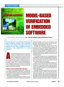
Figure 1.
IoT-Lab platform (source [2]).
view of the existing solutions to validate WSN protocols is given in Section III. The state of the art of virtual platforms is described in Section IV. The extension of virtual platforms to simulate the network is addressed in Section V and some results are reported in Section VI. Finally, conclusions and perspectives are discussed in Section VII. II. M OTIVATIONS A. Verification Requirements for WSN Applications Protocols are geared to serve a number of needs and constraints, some of which are contradictory (Section II-A1). The resulting compromise (which spans across all layers of the protocol) is complex to implement and also to validate (Section II-A2). 1) Needs and Constraints for WSN Protocols: Let us mention some of the functional needs and constraints that are expected and the implementation complexity resulting thereof: • Fault tolerant links: a protocol must detect and recover from the loss of packets (ensured by the MAC layer), • Tolerance of RF medium transients, using mechanisms such as adaptive routing of packets in a mesh network
(NETWORK layer), Deterministic behaviors: ensuring at least a predictable access and bound end-to-end delays (these are regulatory requirements like in the EN5425 standard for wireless fire alarms; all layers concerned), • A good “link budget”: ratio of emitting power to sensitivity of receiver (determined by PHY layer). • Power saving techniques: a battery lifetime of up to 10 years should be expected (all layers concerned), • Addressing a potentially large number of nodes (determined by the addressing scheme at MAC and NETWORK layers). For many industrial applications, the requirement on data rate (few bits/s up to 30kb/s typically) is not stringent. These are commonly referred to as Low Throughput Networks. 2) The Complexity of the Stacks Implementation and Validation: Protocol stack implementation concerns concurrent (layers work in parallel) and real-time programming: timers, interrupt handling and task scheduling among layers. In a protocol implementation, the MAC layer is usually the piece of code that carries the most stringent timing requirements, as it is the layer responsible for reception (avoiding overloading and packet losses), and scheduling of time slots (time to speak, time to listen, as well as sleep and wakeup time on whose precision energy-saving depends). State machines and their timeouts, the scheduling of sleep and wakeups, as well as time slots among a highly distributed and asynchronous systems, make the implementation and validation even more challenging tasks. •
B. Development and Validation is Artisan Work Currently, wireless protocols are developed in C and there is no framework for developing stacks that would provide enough abstraction (despite early work like [3], [4]). Furthermore, validation heavily relies on human driven testing of the real platform and can take a very long time in the project. Model-based development environments exist (Keil, Carbon, OVP, etc.) and it is an increasing practice to test on models first. However, to the best of our knowledge, none of these environments is specifically geared to efficiently validate highly-distributed, real-time software, such as protocols. C. The Ability to Reproduce Bugs One of the greatest benefits of validating a stack on a simulator is that the scenario execution can be replayed exactly, while usual hardware test-beds cannot truly reproduce the same run, due to the asynchronous nature of the system: the CPUs of network nodes do not share the same clock and even show clock drifts. Moreover, hardware debugging is intrusive as it modifies the execution time of the software being inspected. As a consequence, starting a debug session may prevent the protocol to work at all, leaving no chance to catch bugs affecting real-time features. At the opposite, when debugging simulated models, you may
be able to observe (at source code level) the unmodified realtime behaviors of the software (with respect to a simulated network environment). A simulated test-bench has the power to express situations that are not easily reachable in field tests. In practice, it may take days to reproduce bugs on a hardware test-bench. Simulation can accelerate this time, provided that you have enough CPUs and the model is reasonably fast. In practice, PC-like workstations can simulate radio modules at some 10 times or even 100 times the speed of the real hardware, depending on the level of details required. D. Why is Validating the Binary code of the Stack more Reliable? This soft validation can be done either 1) at the C source level, with the source code of the stack being harnessed with a soft test-bench and compiled for the host PC, or 2) at the binary code level, where the firmware that will run on the real platform is executed on an Instruction Set Simulator (ISS) of the embedded CPU, together with models of peripherals. Validating the source code or a behavioral model of the protocol does only provide a very crude notion of time: basically, all tasks execute instantly [5]. Therefore, it cannot model interrupts and multitasking. Yet the modeling of interrupts occurring nearly anywhere in the code of each layer and each tasks is precisely a major source of bugs: transient errors, hard to reproduce in hardware validation, have their origin in wrong timer programming, missed interrupts or taken too late leading to task scheduling issues, buffer overflows and packet loss. Source code execution is only suitable at early stages of development, for coarse debugging. Validating in software the binary code on a realistic platform model is a much more reliable approach, provided it can simulate the occurrence of interrupts on virtually any instruction of the code. E. The Technical Challenges Validation through models requires that the simulations performed cover all possible conditions actually met on real platforms. There is both good and bad news. The good news is that you do not need your model to be cycle accurate, which would require indeed a modeling of the internal microarchitecture of CPUs, busses and peripherals (all details of intellectual property which are normally kept secret by chip makers). Contrarily, you need your model to be flexible enough to exhibit an envelope of all the possible timing behaviors of the circuits which would, for a CPU, boil down to e.g. having the Instruction Per Cycle (IPC) of the model stochastically fall between 0.2 and 1.2. The bad news is that setting an envelope that is too large may trigger false bugs, which will have to be discarded by hand, one-by-one, making the test phase an exhausting job.
III. R EVIEW OF THE EXISTING SOLUTIONS TO VALIDATE WSN PROTOCOLS Before being deployed, WSN protocols are most generally tested on a physical test bench (or test-bed), in order to evaluate their efficiency in a controlled environment. The test-beds enable experimentation with different aspects of the protocols design, such as the protocol stack, the management of resources and the network optimization. However, the development and testing of protocols onto a physical platform can become quite complex if the number of nodes exceeds a few dozen [6]. Indeed, The sensors are generally small devices that have a limited capacity for debugging and programming. Furthermore, the software deployment and debugging on the nodes require each device to be connected, and thus imply individual manipulation on each node. Finally, the energy supply of sensors generally depends on a battery with a limited lifetime. These difficulties have led to the development of large scale test-beds where several independent experimental sites are interconnected, thus providing a more diverse platform with higher performance levels in order to lead more complex experiments. IoT-Lab (Figure 1) is an example of such a federation that provides a platform with 2,700 sensors over 6 different locations in France [2], for which the tests can be managed through a web interface. Even if the development of test-beds has progressed, limitations remain. Their maintenance is expensive and they take a long time to set up. The scenarios are limited when it comes to environmental conditions (e.g., obstacles, node mobility, interferences). Moreover, test-beds are frequently inappropriate for scenario repetition, as users lack control over several relevant parameters such as those related to the environmental conditions [7].
a few simulators compatible with these constraints. Among those simulators, the most promising ones are Tossim [9], Atemu [10], Avrora [11], Cooja [12], and Worldsens [13]. Atemu, the first instruction-accurate hardware-level simulator, emulates MICA-2 motes and their network. Atemu is precise down to the clock cycle of each individual mote, but this precision hinders the simulators scalability. Moreover, Atemu does not implement some of the main components such as the clock manager [13]; therefore the processor cannot modify its frequency, which means that clock drift and power management cannot be modeled. Tossim, which simulates an entire wireless sensor network based on TinyOS, overcomes the scalability limitations of Atemu. However, it does not simulate applications at the same low level of Atemu, and is not capable of capturing properties related to interruptions or the codes execution time [13]. Avrora is an instruction-accurate simulator written in Java. It combines Atemu’s accuracy and Tossim’s scalability. However, it does not model mode mobility and clock drift. COOJA is a network simulator originally designed to simulate nodes running the Contiki OS. It can emulate the execution of the binary code by associating itself to MSPsim [12]. The latter is an ISS for the Texas Instruments’ MSP430 processor. COOJA has the advantage of being able to simulate nodes with different abstraction levels (network, operating system and machine code level). The Worldsens simulation environment is byte- and cycleaccurate. It offers very precise results on application performance and enables the emulation of binary code by associating WSIM, which models nodes based on the MSP430 processor, and WSNET, which models the network. WSIM and WSNET communicate through sockets, and synchronization is achieved through rendezvous points and a saveand-backtrack mechanism.
B. Advantages and Limitations of Existing WSN Simulators Capable of Executing the Stacks Binary Code
IV. R EVIEW OF THE EXISTING WORK ON V IRTUAL P LATFORMS
Validating the protocol stack’s code on a virtual platform allows detecting and analyzing a significant number of bugs that would be difficult to reproduce or diagnose directly on the hardware platform. Moreover, simulation offers a better visibility of the system than test-beds and allows collecting information regarding the code’s performance, the modeled physical platform or the protocol itself. Many WSN simulators have been developed. The most frequently used simulators (e.g., NS-2 and OMNeT++) do not provide models of the internal architecture of the nodes. Therefore, the results obtained from simulation need to be considered with caution. Moreover, the majority of these simulators are only based on a behavioral model of the protocol or on its source code [8]. As our objective is to validate the binary code of a protocol stack, we focus on simulators that model the nodes’ internal architecture. There are only
The Virtual platform (VP) is a software model of a system that can be used for early software development and architectural analysis. VP includes processor and peripheral models, potentially supporting pre-silicon development of the entire software stack up to the applications level. VPs usually provide a simulation and debugging environment. While early virtual prototyping solutions required proprietary models, many now use SystemC models based on the Accelera Transaction-Level Modeling (TLM) standard [14] and the IEEE-1666 SystemC standard [15]. VP reduces software development costs and time to market. It improves quality and enables earlier and more frequent hardware/software integration. It can also provide fairly complete software that helps hardware designers verify designs before detailed implementation. The primary drawback is that virtual prototypes lack time accuracy. They also require their own
A. Limitations of Physical Test Benches
high-level abstraction models. Other common limitations include difficulty in plugging in third-party tools, separate hardware and software debug environments that require a long manual data transfer process between hardware and software teams, and performance that does not scale. Support for programming and debugging multi-core SoCs is lacking in some commercial offerings. A. QEMU QEMU (Quick EMUlator) is a popular open source environment for rapid prototyping of virtual platforms, which can emulate several target CPUs on several hosts [16]. It relies on dynamic binary translation [17] of the target CPU application code: blocks of the target instructions are optimized and translated into instructions executable by the host machines CPU. The translated blocks are stored in a cache for future use. These optimizations allow keeping the execution speed close to native execution. The platforms modelled on QEMU are generally composed of a processor model, a memory manager (MMU), a memory model and the memory mapping managed by the MMU. B. Open Virtual Platform (OVP) Imperas Open Virtual Platform consists of a set of open source C-based platform descriptions and a closed-source CPU emulator supporting several CPU instruction sets. As in QEMU, CPU emulation is based on dynamic binary translation. The CPU emulator and the other libraries are also available as SystemC-wrapped TLM components so that they can be simulated with user-provided SystemC/TLM modules.
models interact by using memory registers mapped onto SystemC ports and inter-process communication primitives. TLMu [23] is a modified version of QEMU that integrates with SystemC TLM-2.0 models. It is possible to create TLM-2.0 systems with multiple TLMu cores of different architectures. Each TLMu instance may provide a bare CPU core or a partial system with devices. Regarding OVP/SystemC co-simulation, Imperas provides a TLM-wrapped version of its CPU simulator to be included in TLM 2.0 scenarios [24]. The approach is similar to the previously introduced TLMu for QEMU. In [25] a virtual peripheral attached to the QEMU/OVP model of the bus is used to redirect read/write operations to SystemC. Communication between the two worlds is based on shared memory and thread synchronization primitives which prevent the use of expensive interprocess communication mechanisms (like sockets). V. E XTENSION OF V IRTUAL P LATFORMS FOR N ETWORK S IMULATION Solutions reported in Sections IV-C and IV-D, together with a SystemC extension for network modeling, allow simulating not only the HW/SW of a network node but also the communication environment in which the node operates. For instance, in [19], [26], a complete WSN scenario has been simulated by connecting an ISS with SCNSL. Let us denote the results of this interconnection as Networked Virtual Platform (NVP). A. SystemC Network Simulation Library
C. SystemC-based virtual platforms While commercial VPs provide their specific simulation engines for CPU emulation, another approach consists in modeling the CPU by using standard hardware description languages and, in particular, SystemC which allows higher abstraction and therefore faster execution. In [18] authors present a method for designing a SystemC-compliant ISS. In [19], ST-Microelectronics verifies power management policies by using a complete C/SystemC model of a Systemon-Chip named ReISC. D. QEMU/OVP and SystemC co-simulation A common industrial case consists in the need to re-use legacy models already available in SystemC. To avoid recoding them in the native language of a commercial VP (e.g., OVP), a solution consists in making SystemC executable model to interact with the VP tool. Traditionally, this kind of interaction is named co-simulation because tools keep their own identity and behavior. In [20]–[22] authors describe a design flow in which verification is based on QEMU for CPU and SystemC for hardware peripherals. QEMU and SystemC executable
Figure 2.
SCNSL internal architecture (source [27]).
SystemC Network Simulation Library (SCNSL) [27] is an extension of SystemC to allow modeling packet-based networks such as wireless networks, ethernet, fieldbus, etc. As done by basic SystemC for signals on the bus, SCNSL provides primitives to model packet transmission, reception, contention on the channel and wireless path loss. The use of SCNSL allows to rely on a single simulation environment (i.e., SystemC) to model hardware and communication aspects of networked embedded systems.
Figure 3.
Interconnection of the virtual platform with SCNSL.
The architecture of SCNSL is depicted in Figure 2. Tasks are used to model node functionality provided by software and digital hardware components in the actual system. From the point of view of the network simulator, a task is just the producer or consumer of packets. However, for the system designer, task implementation is crucial and many operations are connected to its modeling, e.g., change of abstraction level, validation, fault injection, HW/SW partitioning, mapping to an available platform, synthesis, and so forth. For this reason the TaskProxy is introduced, which decouples task implementation from the back-end which simulates the network. This solution ensures a stable interface between the TaskProxy and the simulation kernel and, at the same time, provides complete freedom in the modeling style for the Task, e.g., as interconnections of basic blocks or behavioral. Tasks are hosted by Nodes, which are the abstraction of physical devices. Thus, tasks deployed on different nodes communicate by using the API provided by SCNSL for the network communication, while tasks deployed on the same node communicate by using standard SystemC communication primitives (e.g., signals, FIFOs, TLM primitives). The Channel represents the transmission medium, and SCNSL provides models for both point-to-point (full-duplex, halfduplex and unidirectional) and shared channels. In this work the shared channel has been used to model a wireless link with its various communication aspects. Packet manipulation is a key concept for network simulation. It can be used to implement packet-processing blocks (e.g., queues, tracing or filtering mechanisms) and protocols. The Communicator is an SCNSL component implementing a packet-manipulation interface. B. Interconnection between the virtual platform and SCNSL Figure 3 shows how to interconnect a virtual platform with SCNSL. We assume that the WSN scenario consists of several nodes and, for one of them, we are interested
in the detailed simulation of interactions among software, hardware and network while the other nodes are modeled at pure behavioral level. The dashed box contains the detailed node model. CPU, bus, and peripherals are simulated by the traditional VP (implemented in SystemC, QEMU, OVP, or even a commercial one). Software is compiled with the CPUspecific toolchain and the corresponding binary is loaded into the model of the memory. The core of the interaction is the thick edge box in the Figure. It can represent either a network interface directly attached to the bus or the interconnection of an external network chip with a serial interface (e.g., SPI, I2C, UART) attached to the bus. In case of a pure SystemC VP, all the interconnections can be implemented as TLM sockets. In case of non-SystemC VPs (e.g., QEMU, OVP, etc.) the component attached to the bus (denoted as “virtual device” in the Figure) is a special peripheral acting as a bridge between the VP and SCNSL. From one side it is connected to the bus and is seen by the CPU as a set of memory-mapped registers; from the other side it interacts with SystemC and, in particular, with an instance of the SCNSL Task which is able to send/receive packets on the network. From the SCNSL perspective, each task instance is connected to the hosting node by using standard TLM sockets. All the nodes are bound to the model of the channel which simulates the mutual effect of all packet transmissions. VI. S IMULATION R ESULTS This Section presents an actual example following the architecture of Figure 3. Since we aim at showing the use of a networked virtual platform for the verification of communication software, a simple protocol has been implemented as software and some experiments have been performed to show that the simulation environment may affect its expected behavior so that verification can be compromised. A. Setup The protocol implements the conventional “Stop-andWait” re-transmission scheme between a sender and a receiver node. The former is modeled in detail by using the virtual platform while the latter is represented by a behavioral description in SCNSL. The sender transmits a sequence of bytes obtained from the application layer (for instance the transmission of sensed data); after the transmission of each packet, it waits a given amount of time (denoted as “timeout”) checking if an acknowledge arrives from the receiver. As soon as the acknowledge is detected, the sender transmits a new packet. Otherwise, if no acknowledge arrives before the timeout, the previous packet is re-transmitted. This protocol is well-known and so simple to be correctly implemented in the software executed by the VP. The interface between the CPU and the network interface consists of three memory-mapped registers:
Algorithm 1: C ODE EXECUTED INSIDE THE PROCES SOR . 1 Loop: 2 Increment PROGRESSIVE; 3 Send: 4 Write PROGRESSIVE into WDATA; 5 Using the XOR operator, switch the value of STROBE, from 1 to 0 or vice versa; 6 Reset TIMEOUT; 7 Timeout: 8 Increment TIMEOUT; 9 Check if TIMEOUT exceeded the maximum number of loops for timeout; 10 If timeout exceeded the maximum value goto Send; 11 Read the last value of received acknowledge from RDATA; 12 If RDATA is different from PROGRESSIVE goto Timeout; Goto Loop; 13
WDATA - Data written into register are ready to be transmitted. • STROBE - Every change of this register notifies that there are new data in WDATA ready to be sent. • RDATA - Data read from this register have been received from the network. To simplify experiments, the Stop-and-Wait protocol has been implemented as Assembly code directly on the bare hardware without the presence of an operating system. The waiting functionality has been implemented as a loop with a maximum number of iterations (loop bound). The pseudocode of the sender’s implementation of Stop-andWait protocol is shown in Alg. 1. To simplify the software, we assume that the application wants to send a progressive number (denoted as PROGRESSIVE) which is sent back by the receiver as acknowledge. This algorithm was translated into Assembly code for ARM and MIPS processors and loaded into the corresponding virtual platforms. The network scenario consists of these two nodes connected by a shared channel. •
B. Co-simulation scenarios To show the flexibility of using networked virtual platforms to develop network protocols, several scenarios have been prepared as reported in Table I. Two types of processors have been tested, i.e., ARM and MIPS. System designers can easily test different hardware architectures to choose the most suitable one for their target application. QEMU, OVP and pure SystemC are used to model the CPU. Regarding synchronization between the virtual platform and the network simulator, in case of QEMU no mechanism is present, while, in case of OVP, two different
Table I C O -S IMULATION SCENARIOS
VP Simulator
Language
QEMU-ARMv7 SystemC-MIPS-Lite OVP-SCB-MIPS32 OVP-SCB-ARMv7 OVP-TLM-MIPS32 OVP-TLM-ARMv7
(C) (SystemC) (C) (C) (SystemC-TLM) (SystemC-TLM)
Synchronization with SCNSL Not present Native Support By EDALab By EDALab By Imperas By Imperas
Simulation time (s) 2.27 16.09 1.84 2.06 14.07 13.67
synchronization approaches have been tested, i.e., SystemCBridge (SCB) described in [25] and TLM-wrapping [24]. From the synchronization perspective, the pure-SystemC case is the reference scenario because both the hardware and the network are modeled upon the same SystemC kernel. The Table reports the time spent by the host (Intel Xeon at 2.53GHz running Linux OS) to simulate the transmission of 1,000 packets (with a given network round trip delay of 360µs the application should spend around 0.5s in a reallife test bed). It is worth noting that the synchronization provided by SystemC in rows 2, 5, 6 leads to higher simulation time because it is more accurate. The next Section discusses the relationship between accuracy and simulation effort. C. Impact of synchronization Synchronization between VP and SCNSL is the crucial aspect for this kind of simulation tool. We can use the adopted experimental scenario to discuss synchronization issues. Such scenario contains two concurrent processes, i.e., HW/SW and network. After having sent a packet, software should check for the acknowledge for a given maximum amount of time which is defined in terms of loop bound (depending on both CPU type and clock frequency). Concurrently the network delivers the packet to the receiver and the acknowledge back to the sender; the corresponding round trip time is a property of the network. While in a real test bed, both intervals are measured against the same time scale (i.e., the real time), in networked virtual platforms there is a time scale for each simulation engine, i.e., QEMU or OVP for the CPU and SystemC for the network. The advance of time in each simulation engine depends on the complexity of the contained model, the efficiency of the simulator and the scheduling of the host operating system. The perfect synchronization scheme consists in performing a “rendezvous” between the two simulators at each time progress in each of them; clearly this scheme leads to a significant increase of simulation time as witnessed by row 2 of Table I which represents the ideal synchronization because a single SystemC engine is used. Commercial co-simulation adopts a faster but sub-optimal approach in which time scales are realigned periodically after a Synchronization Quantum which
Table II I MPACT OF SYNCHRONIZATION (OVP-SCB-MIPS32 SCENARIO ) Synch. Quantum (µs)
Min no.
0.1 0.2 0.3 0.4 0.5 0.6 0.7 0.8 0.9 1.0
24 24 24 25 26 27 30 30 32 35
Timeout loops Max Diff. from time expected (µs) (µs) 360 0 360 0 360 0 375 -15 390 -30 405 -45 450 -90 450 -90 480 -120 525 -165
No. synch. points
Host time (s)
1207380 1019470 877733 807873 755030 741585 631686 547625 486277 428464
2.53 2.36 2.07 1.89 1.85 1.84 1.84 1.81 1.81 1.78
is a configuration parameter of the tool. To show the impact of Synchronization Quantum on simulation speed and accuracy, a reference scenario has been created in which the network is reliable-by-construction since no packet (data and acknowledge) can be lost and the total round-trip time is constant and equal to 360µs. The loop bound used for the waiting timeout in Stop-andWait software implementation has been chosen to be the minimum one exceeding the round-trip time so that no re-transmission is needed. If re-transmissions occur during simulation it means that the networked virtual platform introduces artifacts that make verification unreliable. With a MIPS32 CPU executing the Alg. 1 at 1MIPS, the minimum loop bound is 24. The second column of Table II shows the minimum loop bound required to avoid re-transmission as a function of the Synchronization Quantum (reported in the first column). It can be noticed that with synchronization periods of up to 0.3µs the simulated behavior is the same as expected in real life, while with coarser synchronization the minimum timeout would lead to re-transmissions which are not present in a real life test bed. Therefore, insufficient synchronization accuracy may lead to artifacts that limit the verification capability of the tool. Clearly, a shorter Synchronization Quantum leads to a higher number of “rendez-vous” during simulation (as reported by the fifth column of the Table) and thus a higher simulation time (reported in the last column). Finally, the networked virtual platform allows debugging and profiling the communication software. For instance, the third column reports the maximum time spent by the simulated CPU in the timeout loop (such time depends on the value of the loop bound) while the fourth column reports the difference with respect to the expected time (i.e., 360µs). VII. C ONCLUSION AND P ERSPECTIVES We have shown how networked virtual platforms enable the simultaneous simulation of a network scenario and the hardware platform of the node, thus allowing the complete test of the binary code of a protocol without the need for its
source code. The simulation environment we have shown uses co-simulation between a SystemC network simulator and well-known virtual platforms (i.e., QEMU and OVP). The great number of hardware platforms supported by these tools extends the approach to a wide range of protocols for all kinds of networked embedded systems. Nevertheless, we have shown that synchronization is a crucial point to create a reliable tool for verification. If HW and network simulators are not properly synchronized, it is impossible to firmly state that protocol implementation is correct. Protocol validation through simulation would be a valuable tool for the industry and academia. Several simulation platforms already exist for WSN and a few of them allow simulating the execution of the protocols binary code (with limited platform models). Nevertheless, none of them allows comparing protocol properties against simulation. Future work aims at developing a methodology to verify that a protocols behavior (when its binary code is executed on an accurate node model) complies with its property specification. Therefore, the protocol properties need to be inserted in the simulation environment, for example in the form of assertions in the code, in order to halt the simulation as soon as a protocol property is violated. Finally, the simulation environment could be further improved with debugging capabilities, such that if the simulation is halted by a property violation, it is possible to trace the bug back to its origin in the source code. ACKNOWLEDGMENT The authors would like to thank Alessandro Lonardi and prof. Graziano Pravadelli from University of Verona for their great support and experience on OVP simulation. R EFERENCES [1] M. Aboelaze and F. Aloul, “Current and future trends in sensor networks: a survey,” in Wireless and Optical Communications Networks, 2nd IFIP International Conference on, March 2005, pp. 551–555. [2] G. Papadopoulos, J. Beaudaux, A. Gallais, T. Noel, and G. Schreiner, “Adding value to WSN simulation using the IoT-LAB experimental platform,” in Wireless and Mobile Computing, Networking and Communications (WiMob), 2013 IEEE 9th International Conference on, Oct 2013, pp. 485– 490. [3] S. Vuong, A. Lau, and R. Chan, “Semiautomatic implementation of protocols using an Estelle-C compiler,” Software Engineering, IEEE Transactions on, vol. 14, no. 3, pp. 384– 393, Mar 1988. [4] J. A. Ma˜nas and T. d. Miguel, “From LOTOS to C,” in Proceedings of the First International Conference on Formal Description Techniques. Amsterdam, The Netherlands, The Netherlands: North-Holland Publishing Co., 1989, pp. 79–84. [5] T. Chang, T. Watteyne, K. Pister, and Q. Wang, “Adaptive synchronization in multi-hop TSCH networks,” Computer Networks, vol. 76, pp. 165–176, 2015.
[6] C. B. des Roziers, G. Chelius, T. Ducrocq, E. Fleury, A. Fraboulet, A. Gallais, N. Mitton, T. No¨el, and J. Vandaele, “Using SensLAB as a first class scientific tool for large scale wireless sensor network experiments,” in Proceedings of the 10th International IFIP TC 6 Conference on Networking Volume Part I, ser. NETWORKING’11. Berlin, Heidelberg: Springer-Verlag, 2011, pp. 147–159. [7] G. Coulson, B. Porter, I. Chatzigiannakis, C. Koninis, S. Fischer, D. Pfisterer, D. Bimschas, T. Braun, P. Hurni, M. Anwander, G. Wagenknecht, S. P. Fekete, A. Kr¨oller, and T. Baumgartner, “Flexible experimentation in wireless sensor networks,” Commun. ACM, vol. 55, no. 1, pp. 82–90, Jan. 2012. [8] D. Camara, H. Tazaki, E. Mancini, T. Turletti, W. Dabbous, and M. Lacage, “Dce: Test the real code of your protocols and applications over simulated networks,” Communications Magazine, IEEE, vol. 52, no. 3, pp. 104–110, March 2014. [9] P. Levis, N. Lee, M. Welsh, and D. Culler, “TOSSIM: Accurate and scalable simulation of entire TinyOS applications,” in Proceedings of the 1st international conference on Embedded networked sensor systems. ACM, 2003. [10] J. Polley, D. Blazakis, J. McGee, D. Rusk, and J. S. Baras, “ATEMU: a fine-grained sensor network simulator,” in Sensor and Ad Hoc Communications and Networks. 445 Hoes Lane, Piscataway, NJ 08854-4141 USA: IEEE, 2004, pp. 145–152. [11] B. L. Titzer, D. K. Lee, and J. Palsberg, “Avrora: Scalable sensor network simulation with precise timing,” in Information Processing in Sensor Networks. 445 Hoes Lane, Piscataway, NJ 08854-4141 USA: IEEE, 2005, pp. 477–482. ¨ [12] J. Eriksson, F. Osterlind, N. Finne, N. Tsiftes, A. Dunkels, T. Voigt, R. Sauter, and P. J. Marr´on, “COOJA/MSPSim: interoperability testing for wireless sensor networks,” in Proceedings of the 2Nd International Conference on Simulation Tools and Techniques, 2009, pp. 27:1–27:7. [13] A. Fraboulet, G. Chelius, and E. Fleury, “Worldsens: Development and prototyping tools for application specific wireless sensors networks,” in Information Processing in Sensor Networks, 2007. IPSN 2007. 6th International Symposium on, April 2007, pp. 176–185. [14] L. Cai and D. Gajski, “Transaction level modeling: An overview,” in Proceedings of the 1st IEEE/ACM/IFIP International Conference on Hardware/Software Codesign and System Synthesis, ser. CODES+ISSS ’03. New York, NY, USA: ACM, 2003, pp. 19–24. [15] OSCI and IEEE, “IEEE Std 1666 - 2005 IEEE Standard SystemC Language Reference Manual,” IEEE Std 1666-2005, pp. 1–423, 2006. [16] F. Bellard, “QEMU, a fast and portable dynamic translator,” in USENIX Annual Technical Conference, FREENIX Track, 2005. [17] K. Ebcioglu, E. Altman, M. Gschwind, and S. Sathaye, “Dynamic binary translation and optimization,” Computers, IEEE Transactions on, vol. 50, no. 6, pp. 529–548, Jun 2001.
[18] N. Pouillon, A. Becoulet, A. de Mello, F. Pecheux, and A. Greiner, “A generic instruction set simulator API for timed and untimed simulation and debug of MP2-SoCs,” in Rapid System Prototyping, 2009. RSP ’09. IEEE/IFIP International Symposium on, June 2009, pp. 116–122. [19] P. Sayyah, M. T. Lazarescu, S. Bocchio, E. Ebeid, G. Palermo, D. Quaglia, A. Rosti, and L. Lavagno, “Virtual platformbased design space exploration of power-efficient distributed embedded applications,” ACM Trans. Embed. Comput. Syst., vol. 14, no. 3, Apr. 2015. [20] M. Monton, J. Carrabina, and M. Burton, “Mixed simulation kernels for high performance virtual platforms,” in Specification Design Languages, 2009. FDL 2009. Forum on, Sept 2009, pp. 1–6. [21] M.-C. Chiang, T.-C. Yeh, and G.-F. Tseng, “A QEMU and SystemC-Based cycle-accurate ISS for performance estimation on SoC development,” Trans. Comp.-Aided Des. Integ. Cir. Sys., vol. 30, no. 4, pp. 593–606, Apr. 2011. [22] M. Becker, G. Di Guglielmo, F. Fummi, W. Mueller, G. Pravadelli, and T. Xie, “Rtos-aware refinement for tlm2.0based hw/sw designs,” in Design, Automation Test in Europe Conference Exhibition (DATE), 2010, March 2010, pp. 1053– 1058. [23] “Transaction level eMulator http://edgarigl.github.io/tlmu/.
(TLMu),”
2011,
[24] “Using OVP models in SystemC TLM2.0 platforms,” 2015, http://www.ovpworld.org/documents/OVPsim Using OVP Models in SystemC TLM2.0 Platforms.pdf. [25] F. Cucchetto, A. Lonardi, and G. Pravadelli, “A common architecture for co-simulation of systemc models in qemu and ovp virtual platforms,” in Very Large Scale Integration (VLSISoC), 22nd International Conference on, Oct 2014, pp. 1–6. [26] F. Fummi, G. Perbellini, D. Quaglia, and A. Acquaviva, “Flexible energy-aware simulation of heterogenous wireless sensor networks,” in Design, Automation Test in Europe Conference Exhibition, 2009. DATE ’09., April 2009, pp. 1638–1643. [27] “SystemC Network Simulation Library – version 2,” 2013, http://sourceforge.net/projects/scnsl.