The Construction of Verification Models for Embedded Systems A. Mader! , H. Wupper, and M. Boon!! 1
2
Department of Computer Science, University of Twente, The Netherlands Computing Science Department, Radboud University Nijmegen, The Netherlands 3 Department of Philosophy, University of Twente, The Netherlands,
[email protected],
[email protected],
[email protected]
Abstract. The usefulness of verification hinges on the quality of the verification model. Verification is useful if it increases our confidence that an artefact bahaves as expected. As modelling inherently contains non-formal elements, the quality of models cannot be captured by purely formal means. Still, we argue that modelling is not an act of irrationalism and unpredictable geniality, but follows rational arguments, that often remain implicit. In this paper we try to identify the tacit rationalism in the model construction as performed by most people doing modelling for verification. By explicating the different phases, arguments, and design decisions in the model construction, we try to develop guidelines that help to improve the process of model construction and the quality of models.
1
Introduction
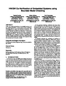
Computer aided verification is a success story. Many years of fruitful work went into sophisticated algorithms, data structures and tools; the size of (automatically) verifiable problems is increasing; new classes of verifiable problems are being found; and also hardware progress allows to deal with larger and larger systems. Many cases have demonstrated the usefulness or potential usefulness of computer aided verification. In the end, however, we are not interested in the properties of a model, but in the correct behaviour of artefacts in physical reality, represented by the bottom line in figure 1. (Computer aided) verification consists in analysis of formal descriptions of mathematical models of such artefacts, represented by the top line in figure 1. Our initial question is therefore: To what extent increases verification our confidence that the artefact behaves in the desired way? By verification we mean, of course, verification of mathematical model against some property. There are two immediate answers to this question, reflecting two different positions, the rationalist’s and the engineer’s position. The rationalist answer !
!!
supported by NWO project nr. 632.001.202, Methods for modelling embedded systems supported by NWO project 016.038.321, Using science in technology: towards a philosophy of the engineering sciences
2
A. Mader, H. Wupper, M. Boon structure blue print, verication model
properties
proof
formal properties
mathematical world formalising
modelling
physical world embedded system, artefact
condence
behaviour, requirements
Fig. 1. Objects relevant in the context of verification
is: formal verification cannot guarantee that an artefact has a certain behaviour in physical reality; verification can only be used as a debugging technique. The engineering position is: the quality of the result from verification is as high as the quality of the model that went into verification. In this paper, we elaborate the engineering point of view, with the goal to improve both, the quality of models and the modelling process, and the interpretation of verification results. Modelling cannot be a purely formal process, as it bridges between an object of the physical world, (in our case an embedded systems, or artefact) and an object in the mathematical world, the model (see also figure 1). In the tradition of Popper a sharp distinction is made between two phases in scientific research, the context of discovery and the context of justification. Only the justification of knowledge can be formalised, and is therefore the objective and rational part. The construction of a model, on the other hand, involves non-formal elements and requires creativity. This is considered the domain of psychology. We, however, argue that even if the modelling process cannot be formalised this does not imply that it is irrational. The distinction above does not conceive the way models are constructed. From the engineering point of view, construction and design is to a large extent educated creativity. By this we mean that construction in the first place is not a process of unpredictable geniality, but follows a discipline of thinking, proven standard-arguments and steps. In most cases, modelling is not subject to radical design, where something entirely new is created, but we apply the known, adequate abstractions, decompositions, idealisations and patterns ([20, 3, 7]). It is the context of discovery that we want to investigate, but in order to emphasize the rationality present in this process, we prefer to call it context of construction. Our intention is to identify the tacit rationalism as applied by most people doing modelling for verification. By explicating the different phases, arguments,
The Construction of Verification Models for Embedded Systems
3
and design decisions in the model construction, we try to develop guidelines that help to improve the process of model construction and the quality of models. Accordingly, we do not claim that our method should replace existing modelling methods, languages, and tools, that concentrate mainly at formal and formalisable aspects. We believe that systematic attention to and documentation of non-formalisable but rational aspects add value to the reader’s favourite formal modelling techniques. We also believe that the method elements presented here help not to get lost in details, but to construct models that contain not more information than it is enough for the verification of the desired properties. We consider an embedded system as a given. Therefore, an important difference to common engineering design is that the verification model is constructed after the design of the artefact. The designer of the artefact has taken a number of design decisions, and our modelling process can follow these. The structure of the paper is as follows. Related work is contained in section 2. In section 3 we propose a taxonomy of decisions for model construction. This taxonomy is based upon general aspects of models that are specified for verification models. Section 4 suggests a way of organising and structuring the arguments and decisions that are taken, leading to a formal description of an artefact. We conclude with section 5.
2
Related work.
A lot of work has been done around formalising the first steps of the waterfall model of software engineering [17]. Requirements analysis (see e.g. [16], [8]) starts from more or less vague ideas, deals with misconceptions and conflicting stakeholders’ wishes, and aims at a formal conceptual model of the application domain. Construction models can be developed systematically (see e.g. [12], [21]) and formalised in a number of well-defined formal languages (e.g. TLA+ [13]) or graphical notations (e.g. Statecharts [11]). More general and related principles of design are discussed in, e.g., [4, 19]. The resulting models, however, which aim to be complete, can be too complex for present day verification tools. This is why we focus on verification models: models that contain just enough to verify certain properties but are much smaller than complete construction models. For them we have in principle the same list of quality aspects as they are in the list of attributes of a well-written software requirementspecification [5]. Verification models should, of course, be derived from conceptual domain models and construction models, but even if these are available at all, one can easily get lost in their many details. Therefore, we need a systematic way to derive a minimal model w.r.t. a verification problem - either from a construction model or, more realistic, from implicit knowledge and informal diagrams about an existing artefact. Many papers on formal methods describe successful verification on the basis of such verification models. But these usually concentrate on the formal part of the story and pay less attention to model construction and quality.
4
A. Mader, H. Wupper, M. Boon
Many papers explain a method w.r.t. a specific modelling language. We try to be language- and tool-independent. The method proposed in section 4 can be used in combination with any specification formalism that allows to deal with assumptions and commitments and to prove that a model satisfies a property. To emphasise this, we shall not give formal examples but hope that the reader can follow the running example given in natural language and convert it to her favourite formalism. The engineering position on design can be found in [18, 20, 7]. In [4] design within computer science, following the engineering position, is elaborated. The construction of verification models shares many aspects with these. The difference is mainly contained in the requirement for small models and in the fact that in the context here, we follow the design of the artefact for the design of the model. In [6] the construction of verification models for hybrid systems is investigated. The relevant questions to answer for modelling of hybrid systems can be mapped directly to our taxonomy of design decisons, which is more general.
3
A taxonomy of decisions for model construction.
When, during modelling, assumptions and the non-formal decisions are made explicit, they can be discussed and questioned, and the results of verification can be better interpreted. This should increase the quality of models—even if the number of non-formal decisions might be too large to make them all explicit and accordingly we never can be sure to have a “correct” model. In this section we propose a taxonomy of modelling decisions. It can be used as a checklist, which decisions have to be made explicit. Note, that the classes identified are not orthogonal, but mutually related. A number of decisions that define and constrain the verification model have to be taken prior to the actual model construction. Many of these can only be approximative and have to be refined during the actual model construction, when the necessary knowledge about what is given and what is needed can be matched. The structure and organisation of the decisions during model constructions is subject of section 4. What is the object of modelling? Our object of modelling, the embedded system, consists of a control part and a physical part, which without loss of generality we shall call plant. We reserve the term environment for everything that is not object of modelling. When the interaction of control and physical part is essential for the properties to be verified, we must model them both. But not in full depth. If, for example, we assume that the controller’s hardware and operating system behave correctly, we do not need to model circuit and o.s. code. When we assume that the engineers have done their work properly, we can take the blueprint of the plant as basis for a model instead of modelling all nuts and bouts. Also, we may restrict the breadth of modelling to a well-chosen fragment of the system.
The Construction of Verification Models for Embedded Systems
5
The specific choice will depend on the properties to be verified, viz. on the purpose of a model, to be discussed below. The method we propose in 4 should help to take these decisions at the right moment and also to decide which assumptions about the environment are needed. The environment cares for too many things to be modelled altogether beforehand— think of gravity, temperature, humidity, power supply. But during a systematic modelling proces, starting from a property to be verified, we might find that the right temperature is essential. Likewise, gravity may be essential when we model the flow of liquid from one container to another. What is the purpose of the model? The purpose of a verification model is verification of some properties only, in contrast to, e.g., specification and design models, which have to cover more. For a coffee machine, for example, we might use different models for timing aspects, such as the time distance between two cups of coffee is not less than 20 seconds, and for quality aspects, such as there will never be soup powder in the coffee. Specific for embedded systems is the interdisciplinary character of the knowledge involved. Therefore, an additional purpose of models of embedded systems is knowledge integration. Typically, the physical part of embedded systems is built and understood by domain specialists, other than software engineers, as, e.g., chemical engineers, mechatronics experts, and process engineers. During modelling the relevant knowledge of these experts has to be identified and transformed into the model. One of our examples here is a valve in a chemical plant, opened and closed by a controller. How a valve is working precisely, and what effect the behaviour of the valve has on the quantities flowing through a pipe, and what this means for the chemical process, is typically knowledge beyond the scope of a modeller. The modeller learns from a domain expert about the embedded system under consideration, but only when fixing the knowledge in form of a model the domain experts can identify misunderstandings, or, often, lacking domain paradigms. In this process the model has also the purpose of knowledge communication and transfer. This forms a contrast to many other models that take only one perspective on a system. When modelling embedded systems, we therefore have to be aware of this purpose. The decisions that have to be made explicit here belong to the domain knowledge of the engineers. These decisions become mainly relevant during the model construction phase: there, we typically detect that for a further step more knowledge is necessary. Other purposes of a model are maintainability and evolvability, meaning that small changes in the artefact can be transformed efficiently into the model. These have to be supported by the modelling process. What is the pragmatics of the model? How much may it cost to make the model? Can we throw it away immediately, or at the end of the week? If we must keep it for a while, must it be maintained? How long is it going to be maintained, by whom, and what is that allowed to cost?
6
A. Mader, H. Wupper, M. Boon
What are the epistomological criteria of the model? The model has different purposes and in order to meet this purpose we have to specify certain epistomological criteria. We can identify different epistomological criteria (quality criteria) for verification models. In the list below we explain them and discuss possibilities for their evaluation. Some of them may be contradicting in many settings, e.g., simplicity and completeness. When constructing a model we have to decide which criteria should be satisfied, and be aware of the consequences of criteria not being satisfied. When using the model for verification of other properties it has to be checked whether the same epistomological criteria are relevant as for the initial verification problem. For verification models we have in principle the same list of quality aspects as they are in the list of attributes of a well-written software requirement specification [5]. The criteria discussed here come to some extent directly from the requirements for the verification, to some extent from requirements of the model construction process, which should be efficient and reusable (evolvable). – Truthful. Considering our initial question, this is the most obvious quality criterium. The model has to represent the relevant behaviour of the artefact. Coming back to the rationalist view on modelling, we only can falsify models by, e.g., testing. This is reflected in the typical process of model construction, where the first runs of, e.g., a model checker have the purpose of improving the model and removing bugs, rather than proving something about the system. Our main claim is that by making modelling decisions explicit, and break it down in simple steps that support insight, we can increase truthfulness of the model4 . – Complete. Here, completeness is always relative to a property. Deciding wheter a model is complete is in most cases as difficult as the evaluation of truthfulness. – Simple. Simplicity is crucial for computer aided verification: if a model is too large we get stuck in a state space explosion. It is easy to decide whether a model is simply enough, by trying it out on a verification tool. Considering the rapid development in tools and in hardware, this aspect is a moving target. – Understandable. It should be clear which design decisions went into the model derivation, where they were taken, and what are the consequences, including, ideally, what are the faults that are avoided. Understandability can be evaluated by showing the model derivation steps to another person and find out whether she understands the steps taken. – Tracable. Tracability has two different interpretations, going in different directions between artefact and model. The first leads from the model to the artefact: a fault found in the model should be easily traced back to a fault in 4
According to T. Hoare: There are two ways of constructing a software design. One way is to make it so simple that there are obviously no deficiencies. And the other way is to make it so complicated that there are no obvious deficiencies.
The Construction of Verification Models for Embedded Systems
7
the artefact. The second interpretation leads from the artefact to the model: it should be obvious what elements of the artefact went into which design decision and are reflected at which point in the model. – Efficiently constructable and maintainable. This is a quality criterium that is about the modelling process and not the model. However, it is obvious that it is to some extent a result from the two previous quality criteria, understandability and tracability. Evaluation of this criterium can only be performed in pactise. What is the structure that we want to model? One of the most relevant approaches to modelling is decomposition. A prerequesite for decomposition is that we have identified the structure of the artefact, i.e. its components and their interaction. However, we argue that there is no unique structure of the artefact. There are many different structures, and each structure depends on the view we take on an artefact. The oftware engineer has a different view than the power engineer or the mechatronics expert. What views can be taken is for the greatest part education, and to some extent also creativity. We go one step further, and see that structure is not necessarily a property of an artefact. By taking a view on an artefact we impose the structure on it. For example, when we identify the processes running on a system, there is often not a unique solution, we can choose the borders between processes in different ways. Some structures of an artefact we cannot see at all, because we have not learnt to see them. Taking a view on an artefact, we add something to the artefact. Subsequently, we can decompose according to the stucture we identified. There are views that allow for more suitable, or compact, or intuitive decompositions. Taking a certain view on an artefact abstracts at the same time from all other views. When we draw a electric circuit, we abstract from the colour of the resistors. Modelling works along the identification of components, their interactions, ie. causalities, and the assumptions we have about them. When we model a system we need different views. Some causalities and assumptions can be identified within one view and decomposition, sometimes we need different views. An example of the single-view is a recipe-based decomposition. There we extract the information what are the basic (processing-)steps to take, what is their order and what timing requirements are there. An example of the multi-view is a recipe-based decomposition in combination with an instrumental decomposition: when we see that two basic (processing-)steps need the same instruments, we can derive a mutual exclusion requirement for these two basic (processing-)steps. There is a long list of possible decompositions, or views, among them: functional, service-based, process-based, recipe-based, workpiece-based, instrumental, communication-based, and event-based decompositions. Moreover, different views can be mixed within one decomposition. For the moment, the decompositions mentioned here are vague, they are meant only for illustration of the number of possibilities. When elaborating a modelling method we need more precise definitions.
8
A. Mader, H. Wupper, M. Boon
In which mathematical domain do we describe our model? By having concentrated on verification models we have to represent the model in some formal language, in contrast to, e.g., natural language descriptions. Still, the number of possible formal representations is huge. The choice of a suitable mathematical domain is ideally guided by the answers on the previous questions, and related to the expressivness of this domain, respectively the formal language corresponding to it. In practice, often a formal language is chosen, because it is the input language of a powerful tool, or, a language is chosen, because we are familiar with it. Ideally, we make the choice of the formal language to describe the model, discussing alternatives and the consequences of our choice to the purpose of the model, structure we want to express, and the epistomological criteria that have to be satisfied. What idealizations and simplifications are applied? We often have the case that we idealise the behaviour in a model: e.g. messages arrive at a certain point in time, whereas in the system messages arrive during an interval. Then, we (should) have an argument why the properties of the idealised model still say something about the artefact. (Such an argument can also be formal, e.g. using equivalence classes.) When we consider a physical object that we want to model, e.g. a valve, then, typically, we identify the observable behaviour of a valve and invent a description of a valve that mimics the same behaviour. A first choice would be to model a valve as an object with two states, open and closed. Placed in a bigger context with, e.g. a pipe, the state closed of the valve will be defined to be in conflict with a state flowing of the pipe. This may be enough in one certain context. In another context a more detailed observation may be neccessary: valves do not open and close instantaneously, and in the opening and closing phase less amount of fluid passes through than in the completely open state. If small amounts of the fluid are relevant to consider, we need here a model addressing differential equations describing the flow. Possibly, we can also opt for a simplification of differential equations, and possibly we understand that also differential equations provide only an approximation of the physical process and we have to decide whether the error of the approximation is acceptable or not. The choice we take is guided by domain knowledge from, e.g., the chemical engineer, who knows all about valves. It is related to the epistomological criteria as it concerns truthfulness, simplicity, and completeness. It is also related to the purpose of a model, as, e.g., the chemical processes controlled have to be represented in the model adequately, and finally, it is also related to the object of modelling, where the level of granularity of modelling is concerned.
4
Systematic model construction
After the preliminary choices for verification described in section 3, a truthful, minimal, understandable verification model must be constructed. A method to achieve this has first been illustrated in [22]. Its purpose is
The Construction of Verification Models for Embedded Systems
9
– to make decisions explicit and to order them systematically, and thus to break down the arguments used for construction of the verification model into such small and understandable, logically ordered pieces that these together give confidence in the truthfulness of the exercise; – not to go into more detail and not to model a larger part of the artefact than necessary for the property to be verified; – to help take decisions not before they are well-understood. The method is based on the following assumptions: – The artefact under discussion has been constructed by binding together certain parts with well-understood properties such that these parts together bring forward the desired overall property—even if it may be difficult to recognise these parts without the help of a domain expert. – Each physical part of the artefact is required to perform its task (commitment) only as long as its environment guarantees certain conditions like temperature, power supply, and the necessary input (assumption). If we don’t have good reasons to abstract from such assumptions, we write specifications as (assumption, commitment) pairs. The specific notation will depend on the languages used. Below, we shall use the notation ai → ci . – For each physical part, quantitative knowledge is available about the time it needs to perform its task and the quantities of volume, current, voltage etc. it can handle. This means that formulae ai and ci to be found will contain numbers rather than vague terms like as soon as possible. Whichever languages, methods and tools are used for formal verification, the essence of the formal part of verification of embedded systems consists in finding out by means of computer support whether P, X |= S where S = (A → C), the specification of the goal, is a formula defining a desired property of the artefact under discussion, X is a specification of the control program, and P = (a1 → c1 , a2 → c2 , ..., an → cn ) is a set of formulae specifying something we know about the physical parts of the artefact that are to be controlled. A formula, however, cannot directly define a physical phenomenon. The semantics of a formula defines a mathematical object, which hopefully corresponds somehow to the intended physical phenomenon. We reserve the term specification of a physical phenomenon for a formula that defines a truthful (“representative” in the sense of [9]) mathematical model of that phenomenon. Finding a verification model for an embedded system means finding specifications P, X and S. (1) S, the specification of the goal or of the property to be verified, is the first problem. Essentially, there are three possibilities: 1. S is given, for example because the embedded system under discussion is part of a bigger artefact, the design of which requires S. Example: “Each message sent must arrive after at most 100ms” just because otherwise the surrouding system would fail to work.
10
A. Mader, H. Wupper, M. Boon
2. Only a vague idea around the goal is given (“Produce fresh coffee asap”), but the specific implementation determins the quantities (“one cup of 80cc per minute”). In order to formulate a provable S we must somehow extract knowledge about implementation choices. 3. Only a vague idea around the goal is given, but we are content with the verficiation of very general properties (like “Each message must arrive eventually.” or “If something is produced, it must be coffee.”) Without extra knowledge, such specifications are purely academic, as in practice there is no difference between “eventually” and “not yet, and may be not in the next hundred years”. Verification of such a general S, however, can be meaningful in front of a background of exra knowledge, which should always be clearly stated for start. For example: “We have good reasons to assume that, if a message arrives at all, it will arrive soon enough. In this verification problem we only want to focus on construction faults that lead to infinite loops.” or “If the machine produces something at all, it will be a cup per minute fair enough. We only want to exclude that soup powder gets into the coffee due to a control fault.” (2) P, the specification of the plant, machine, or vehicle in which the control is embedded, is a much bigger problem. Usually we have a large, complex physical artefact together with some informal diagrams and descriptions and, in the best case, domain experts that are willing to help with their nowlegde. Our method aims at deriving P = (a1 → c1 , a2 → c2 , ..., an → cn ) together with S in a systematic way, where the a1 → c1 are (hopefully simple) assumptions and commitments for a (hopefully small) number of constituing parts of the artefact. (Example: A mechanical wrist watch can better not be considered as lots of tooth wheels, springs and other strange contraptions; it should be understood as consisting of an oscillator with frequency 5 Hz, a source of mechanical energy, three hands, and a mechanism to bring the frequency of an oscillator down to 1/(60*5), 1/(60*60*5), and 1/(12*60*60*) of its value, respectively.) (3) X, the specification of the control program, can then be understood as the unknown variable in P, X |= S. If the control program already exists, it is tempting to use it—or rather its denotational semantics—as its own specification. But verification of a large program w.r.t. P and S will usually be far too complex for contemporary tools. If we find a specification X just strong enough to ensure P, X |= S we can first prove this and then verify the program against X independently of its environment: the well-understood question of program correctness. The method step by step. We will use a washing machine as running example. The verification problem is: will the control program switch on and off the various engines and operate the various valves in such a way that the result is reasonably clean and dry? Start from C 0 - a simple, general version of the property to be verified. A formula (depending on the language used) that says: “Clean clothes, at any time, immediately!”. We know that we mean “as soon as possible”, but that will not be expressible in most specification languages.
The Construction of Verification Models for Embedded Systems
11
Use expert knowlegde about the artefact to identify a sub-process that somehow contributes to this goal. An obvious choice is: move the clothes in warm water with a detergent.
For that process, find a component in the physical artefact that is used to perform it. In our example, this will be a tumbler together with its engine.
For this component, write a formula a1 → c1 that contributes to C 0 but does not contain more knowledge than necessary to contribute to the overall goal. If clothes, warm water and a detergent are in the tumbler in the beginning, and if the engine is powered for a certain period, the clothes will be rather clean - and wet - in the end. At this moment we may realise that we forgot to require sufficiently dry clean clothes in C 0 .
Obtain knowledge about the quantities the component requires and can handle; incorporate these in a1 → c1 .
This is the moment to decide whether we are modelling a household washing machine of a professional one. In casu, no more clothes than 4.5 kg can be handled, and the process will require 30l of water of 60C and last one hour if it has to remove 99% of the dirt. The c1 will also tell us that there is a lot of dirty water te be disposed of, and that the clothes are wet.
Decide what of the a1 will be ensured by another component of the artefact and what has to be provided by the environment of that artefact.
In our example the warm water will be provided by a built-in heater, while electricity and detergent will have to be provided by the environment.
Decide what of the c1 will have to be dealt with by another component.
As we want rather dry clothes, we need some kind of spin-dryer and a pump. The necessary drain we shall require form the envorinment.
Replace C 0 by a weaker A1 → C 1 that reflects the new state of knowledge.
A1 will require a certain amount of electricity and detergent as well as drains. C 1 will contain the quantities 4.5 kg, 1 hour, and 99%.
Now look at one of the processes that were discovered during the previous step to decrease the “difference” between a1 → c1 and A1 → C 1 . Specify it in the same way as a2 → c2 .
For example, we will find a heater that provides warm water provided it gets cold water and a certain amount of electrical energy.
Adapt A1 → C 1 accordingly, which gives us A2 → C 2 .
A2 is stronger than A1 : cold water and more electricity is required. C 2 , however, is weaker: even more time is taken.
Continue this method, adding new processes and their system components until you arrive at a provable: a1 → c1 , a2 → c2 , ..., an → cn |= An → C n .
In our example, only a pump has to be added. The tumbler, together with its engine powered with a higher voltage and with the pump will do the job.
Not before we have obtained this complete picture, we start with the difficult part of conflicting resources. The specification of one of the processes in our example requires that the water stays in the tumbler for a certain period, while the specification of another one requires it to be pumped out while no new water streams in. A physical tumbler cannot implement both specifications unless it has valves that can be opened and closed. Likewise, engines and pumps must have switches to activate and deactivate them. Adapt the ai of all processes so that they inlude the settings of the necessary valves and switches, giving a∗i .
12
A. Mader, H. Wupper, M. Boon The process pumping the water out of the tumbler, for example, will require the tap to be closed, the drain to be pened and the pump to be switched on.
From these adapted specifications, An → C n can no longer be proved. This is where the control program comes in: Find a specification X such that a∗1 → c1 , a∗2 → c2 , ..., a∗n → cn , X |= An → C n This may involve a scheduling problem, requiring further weakening of An → n C : the overall process may take more time because conflicting sub-processes cannot be executed in parallel.
5
Conclusion
Applications The method proposed here has been challenged in a course in applied formal logic for several years. In the years before our method was taught, the students were mainly trying to model everything they could think of, in order “not to forget anything that might be relevant”, until they got completely lost. Since the method is taught, we can read in many reports that the main insight they got during the course is to systematically leave away the irrelevant and formalise only a minimum. Elements of the method have also been applied in different cases studies, each of which focussed on a certain aspect. In [14] an academic chemical batchplant was modelled and verified. Non-monotonic refinement was used here to construct the model, proofs have been performed with PVS [1]. The case described in [10] is a real-time token protocol. The focus here was on the the explicitness of criteria from the taxonomy section, and Uppaal [2] was used for verification. For [15] a PLC controlled Lego sorter was modelled and verified with Uppaal. The main issue there is the identification of assumptions during model construction. Future Work The taxonomy should be extended by more concrete examples focussing on identified classes of problems. It should have a cookbook form of lists with possible decisions, corresponding modelling solutions and potential faults that are introduced when taking the wrong decisions. The taxanomy has to be evaluated and improved in further cases studies. The modelling elements discussed in this paper can be used for both, apriori and a-posteriori verification. Here, we restricted to the a-posteri case, assuming that the control specification of code is given. In current research it is elaborated how control design can be done using these principles. Additionally, more different decompositions of the embedded system are needed in order to make restrictions to the control explicit. The method described here is independent of a specific verification formalism, method, or tool. IT professionals used to a particular tool but unfamiliar with the methodological view taken here may need an instantiation of the method with their familiar notation and terminology. Acknowldgement: The authors thank Roel Wieringa for discussion and comments, and for contributing the aspect of pragmatics to the taxonomy.
The Construction of Verification Models for Embedded Systems
13
References 1. PVS homepage. http://pvs.csl.sri.com/. 2. UPPAAL home page. http://www.uppaal.com. 3. E. W. Constant. The Origins of the Turbojet Revolution. The John Hopkins University Press, 1980. 4. S. Dasgupa. Design Theory and Computer Science. Cambridge University Press, 1991. 5. A. Davis. Software Requirements: Analysis and Specification. Prentice Hall, 1990. 6. A. Fehnker and B. H. Krogh. Hybrid system verification is not a sinecure: The electronic throttle control case study. In ATVA, pages 263–277, 2004. 7. E. S. Ferguson. Engineering and the Mind’s Eye. MIT Press, 1992. 8. M. D. Fraser, K. Kumar, and V. K. Vaishnavi. Informal and formal requirements specification languages: Bridging the gap. IEEE Trans. Softw. Eng., 17(5):454–466, 1991. 9. R. Frigg. Models and representation: Why structures are not enough. Measurement in Physics and Economics Discussion Paper Series, 2002. 10. F. T. Y. Hanssen, A. H. Mader, and P. G. Jansen. Verifying the distributed realtime network protocol rtnet using uppaal. In Proceedings of the 14th IEEE/ACN MASCOTS, pages 239–246. IEEE Computer Society, January 2006. 11. D. Harel and A. Naamad. The statemate semantics of statecharts. ACM Trans. Softw. Eng. Methodol., 5(4):293–333, 1996. 12. M.A. Jackson. Problem Frames: Analysing and Structuring Software Development Problems. Addison-Wesley, 2000. 13. L. Lamport. Specifying Systems: The TLA+ Language and Tools for Hardware and Software Engineers. Addison-Wesley Longman Publishing Co., Inc., Boston, MA, USA, 2002. 14. A. Mader, E. Brinksma, H. Wupper, and N. Bauer. Design of a PLC control program for a batch plant - VHS case study 1. European Journal of Control, 7(4):416–439, 2001. 15. J. Marincic, A. Mader, and R. Wieringa. Capturing assumptions while designing a verification model for embedded systems. Technical report TR-CTIT-07-03, Centre for Telematics and Information Technology, Univ. of Twente, The Netherlands, Jan 2007. 16. A. Perini, M. Pistore, M. Roveri, and A. Susi. Agent-oriented modeling by interleaving formal and informal specification. In AOSE, pages 36–52, 2003. 17. Winston W. Royce. Managing the development of large software systems. pages 1–9, 1970. 18. D.A. Sch¨ on. The reflective practitoner. Basic Books, 1983. 19. H. A. Simon. The Sciences of the Aartifical. MIT Press, Cambridge, 1981. 20. W. G. Vincenti. What Engineers Know and How They Know It. The John Hopkins University Press, 1990. 21. R.J. Wieringa. Design Methods for Reactive Systems: Yourdon, Statemate and the UML. Morgan Kaufmann, 2003. 22. H. Wupper and A. Mader. System design as a creative mathematical activity. Technical report CSI-R9919, Univ. of Nijmegen, 1999. http://www.cs.kun.nl/ research/reports/full/CSI-R9919.ps.Z.