The control of variable speed wind turbines is a complex problem since they ... shortage of traditional energy source in the near future. ... (The trajectory of the blade of the turbine is approximated to a circle of radius R. For the studied wind .... 700. 800. 900. 1000. 2. 4. 6. 8. 10. 12. 14. 16. 18. 20 k. W in d sp ee d. (m. /s. ) V(k) ...
International Journal of Computer Applications (0975 – 8887) Volume 68– No.11, April 2013
Neural Control Strategies for Variable Speed Wind Turbine Cherifa Brahmi
Mohamed Chtourou
Mohamed Djemel
Electrical Engineering Department National School of Engineers, Sfax, Tunisia
Electrical Engineering Department National School of Engineers, Sfax, Tunisia
Electrical Engineering Department National School of Engineers, Sfax, Tunisia
ABSTRACT The control of variable speed wind turbines is a complex problem since they are considered as nonlinear and time varying systems. In general, classical control techniques do not take into consideration the stochastic and dynamical aspect of the wind and they are not very robust. In order to address these weaknesses, neural approaches are proposed: a direct neural model DNM of the wind turbine is elaborated and then an inverse neural controller INC is developed. The other objective of this study is to optimize the power generated by the wind turbine. To achieve this aim, we have elaborated a neural controller which takes into account the optimal speed of the turbine. Finally, some modifications of the neural control strategy are used to improve the results. The neural controllers were tested with a wind turbine simple mathematical model. The obtained results have shown better performance in comparison with classical control techniques.
control was introduced in [11, 13]. More recently, some nonlinear control laws, such as fuzzy logic controllers and neural network methods, have been proposed [7], and adaptive control has also been studied [14]. Aerodynamic forces acting on wind turbines are turbulent in nature. Wind speed is known to vary stochastically [15, 16]. As a result, it is impossible to predict the captured aerodynamic torque from single point wind speed measurements. Therefore, one is lead to elaborate more adequate control procedures for wind turbines which enable to deal with the presence of uncertainties such as neural controllers [17].
Keywords Wind turbine, non linear system, neural modelling, neural control and hybrid control.
This paper suggests control strategies of a variable speed wind turbine using neural controller. It is structured as follows: We start this study with presenting the mathematical model of the wind turbine. Next, a model based on the neural network is derived in section 3. Section 4 aims to elaborate a neural controller for variable speed wind turbine and to give some improvements of the developed controller. Section 5 is devoted to simulation results and discussions.
1. INTRODUCTION
2. WIND TURBINE MODELING
In recent years, the electrical power generation from renewable energy sources, such as wind, is increasingly attraction interest because of environmental problem and shortage of traditional energy source in the near future. Many studies focused on variable speed wind turbines as a source of wind energy. Structural loads can be reduced and energy capture can be increased with variable speed operation. In addition, the significant power excursions common to constant speed turbines are avoided. However, sophisticated control algorithms are necessary for variable speed wind turbines to be profitable and reliable: intelligent approaches are introduced in control of these machines [1-4]. The objective is to optimize for these machines power efficiency and to enhance quality during operating conditions. Several wind turbine controllers have been proposed for the variable-speed operating regime. Reference [5] defines the control objective as achieving optimal rotational speed tracking while rejecting fast wind speed variations and avoiding significant control efforts that induce undesirable torques and forces on the wind turbine structure. Many control strategies have been proposed in the literature primarily based on linear time-invariant (LTI) models. Classical techniques based on PI or PID controllers [6, 7] have also been used extensively. But they had not given acceptable results especially with the presence of uncertainties. Optimal control has been applied in the linear quadratic (LQ) [8, 9], H-infinity and linear quadratic Gaussian (LQG) [9, 10] forms. Robust
A wind turbine transforms part of the kinetic energy in the wind into electrical power. Wind turbine simulation complexity varies greatly depending upon its objectives. Aero elastic simulators are used to verify dynamic loads and interaction of the components of these large flexible structures. The combination of aerodynamic loading and dynamic response of multiple components requires complex simulators (fig1.).
Fig 1. Wind turbine dynamics [2]. The Wind speed V, considered as a system input, performs on a blade of a wind kinetic pressure Pc which varies with the air density ρ, namely [11]:
8
International Journal of Computer Applications (0975 – 8887) Volume 68– No.11, April 2013
Pc
1 V 2 2
(1)
From this pressure, it is possible to determine the force applied on a given section S as follows:
Fe
1 SV 2 2
The torque Tg will be a control input for the wind turbine and a reference magnitude for the control system of the asynchronous generator. The fundamental equation of dynamics applied to the shaft of the generator determines the evolution of the mechanical speed
(2)
Where S R (The trajectory of the blade of the turbine is approximated to a circle of radius R. For the studied wind turbine R = 21.38 m). Wind power is defined as follows: 2
1 Pv SV 3 2
1 C p Pv SV 3C p ( , ) 2
(4)
Cp is called the power coefficient. This is a dimensionless parameter that expresses the efficiency of aero turbine in transforming the kinetic energy of wind into mechanical energy. For a given aero turbine the coefficient Cp depends on the specific speed λ and the angle of orientation of the blades β (also called setting angle) [12]:
With
Wa R V
Wa is the rotational speed of the turbine.
C p ( ) (
c1
0
c2 ) exp(
c3
0
c4 )
(6)
where : λ0 = λ + 0.02 ; c1 = 101.23 ; c2 = 9.02002 ; c3 = 18.4 et c4 = 0.0552 [4]. The aerodynamic torque Ta is obtained from the captured aerodynamic power and the rotational speed of the turbine. 3 Paer C p SV Ta Wa 2Wa
(7)
The multiplier acts to play the role of adaptor of speed between the output shaft connected to the blades and causing the generator speed shaft. This multiplier is characterized by its gain G, the mechanical speed of the generator Ωmec and the generator torque Tg, we have:
mec GWa Tg
the turbine transferred to the generator rotor
J
Ta G
(8)
(9)
(10)
Jt G2
.
Jt Jg G2
The total mechanical torque
Tmec takes
(11)
into account the
torque from the gearbox, the electromagnetic torque produced by the generator and the torque of the viscous friction which is modeled by the viscous friction coefficient f ( T f
fmec ).
So we have:
J By replacing
d mec Ta Tg f mec dt
(12)
mec and Ta by their expressions yields:
3 dWa C p ( ) SV JG Tg fGWa dt 2Wa
(5)
Several expressions have been used in literature to calculate the coefficient Cp ; [13]-[14]. In this paper, we will adopt the following expression for the power coefficient:
:
Where J is the total inertia that appears on the generator rotor, consisting of the inertia of the generator Jg and the inertia of
(3)
The aerodynamic power appearing at the turbine rotor is given by the following expression [11]:
Paer
mec from the mechanical torque Tmec d mec J Tmec dt
(13)
Thus the equation describing the dynamics of the generator shaft is: dWa SV 3 c3 c1 JG
dt
2Wa
(
Wa R 0.02 V
c2 ) exp(
Wa R 0.02 V
c4 ) Tg fGWa
(14) The dynamic behaviour is described by a nonlinear equation having incertain parameters depending on the wind speed. So a nonlinear first order neural network is used in order to describe the model of wind turbine and get more performant results.
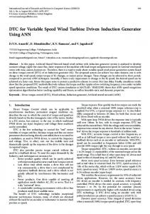
3. NEURAL MODELLING Neural networks have been applied in many engineering fields to deal with problems such as recognition, estimation and control [17, 18, 19, 20, 21, 22, 6, and 2]. There are several types and architectures of neural networks depending fundamentally in the way they learn [23, 24, and 25]. The structure of the used neural network is the multi-layer perceptron. The modeling task is performed over a period spanning 10s. For this horizon and to put the model under severe conditions, we assumed that the wind speed can vary according to the shape shown by the figure 2. The mean value of the wind speed is 7 m/s.
9
International Journal of Computer Applications (0975 – 8887) Volume 68– No.11, April 2013
20 V(k) 18
Wind speed (m/s)
16 14 12 10 8 6
Fig 3. Control structure.
4 2
100
200
300
400
500 k
600
700
800
900
1000
4.1 The INM controller To develop the INM controller, we have used the structure described by the figure 4.
Fig 2. Wind speed profile. The adjustment of the weights involved in this model is given by the following equation:
wijm (t 1) wijm (t ) Where:
J (k 1) wijm (t )
(15)
t and ε denote the number and the iteration step. J means the criterion to be minimized, such as:
1 J (k 1) [Wam (k 1) Wa (k 1)]2 (16) 2 With Wam (k +1) denotes the output of the neural model at the discrete time k +1and Wa (k +1) represents the system output at the same time. The physical model of aero turbine is characterized by nonlinearities, uncertainties and parameter variations which are mainly due to the fact that the aerodynamic torque is highly dependent on wind speed taken as a variable and stochastic variable. So to handle these uncertainties, a learning set has been collected considering a variable wind speed which has been introduced as an input to the dynamic neural model. The representation of such process by linear models does not lead to acceptable performance. So to control this nonlinear system, a nonlinear modelis developed: the direct neural model [26]. The neural modeling can be summarized by the following steps: Step 1: Initialization of the weights. Step 2: For each input vector, adjust the neural model weights according to equation (15). Step 3: When the training convergence is reached stop if not go to step 2. When the neural model gives acceptable performances, it will be used to design neural control strategies.
4. NEURAL CONTROL In this section, the design of the neural controller will be presented (fig 3).
Fig 4. The scheme of development of the INM controller. The INM controller is a feed forward neural network having two inputs: the actual rotor speed wa(k) provided by the DNM and the desired speed wad(k+1) which has been changed randomly during the phase of synthesis. The generator torque Tg (k) is the output of this controller. The adjustment of the weights involved in this controller is given by the following equation:
Wij (t 1) Wij (t )
J 1 (k 1) (17) Wij (t )
Where J1 is the criterion to be minimized during thesynthesis given by:
1 J 1 (k 1) [Wad (k 1) Wa (k 1)]2 (18) 2 With Wa (k +1) designates the output of the MND at the discrete time k +1 and
Wad (k 1)
represents the desired
output at the same time. The synthesis of the INM controller is carried out according to the following steps: Step 1: Initialization of the weights. Step 2: For each input vector, adjust the weights of the INM controller according to equation (17). Step 3: If the training of convergence is achieved stop else go to step 2.
4.2 Optimal neural control In this section, the controller will be developed in order to provide the control action giving the optimal value of the rotor speed.
10
International Journal of Computer Applications (0975 – 8887) Volume 68– No.11, April 2013 The principle of this control strategy is similar to the inverse neural control. The criterion to be minimized during the synthesis is given by:
J 2 (k 1) Where
1 [Waopt (k 1) Wa (k 1)]2 (19) 2
Waopt (k 1) opt
R V (k 1)
is the optimal
rotor speed and λopt= 7is the optimum specific rotational speed. The input vector of this controller is made up of the rotor speed Wa (k), the optimal rotor speed Waopt (k +1) as well as the wind speed V(k). The output is the generator torque Tg (k). The model training is performed following the steps of the back propagation algorithm.
5. SIMULATION RESULTS AND DISCUSSIONS 5.1 Modelling results For different values of the generator torque and for the wind profile given by figure 2, the mathematical model of the wind turbine has been simulated to generate training data base for the direct neural model (DNM). In order to design the neural control, a DNM has to be synthesised to emulate the behaviour of the wind turbine. Since the process is nonlinear first order system, the proposed neural model DNM has three inputs: the rotor speed wa (k ) , the generator torque Tg (k ) and the wind speed V (k ) .
wa (k 1)
is the output of this model (fig 6).
To improve the accuracy of the developed controller some improvements are introduced.
4.3 Improvements of the neural control Two strategies have been adopted to improve the performance of the developed neural controller: iterative aspect and hybrid control.
4.3.1 Iterative aspect At each sampling time, this approach calculates iteratively the control signal by minimizing the following criterion:
Tgiter 1 (k ) Tgiter (k )
J 3 (k 1) Tgiter (k )
Fig 6. Structure of the DNM. The learning base consists measures. The training data input which is the generator interval [1.8011 103,
(20)
Where:
of 700 pairs of input-output are generated using a control torque Tg distributed over the 7.9249 103] (fig 7).
8000
1 J 3 (k 1) [Waopt (k 1) Wa (k 1)]2 2
(21)
7000
This approach consists on operating simultaneously a conventional controller and a connectionist model to improve the control performance (fig 5).
Generator torque (N.m)
6000
4.3.2 Hybrid Control
5000
4000
3000
2000
1000
100
200
300
400
500 k
600
700
800
900
1000
Fig 7. Generator torque.
Fig
The rotational speed of the wind turbine is given by the figure 8.
5. Hybrid control structure. The control action is the sum of two control terms.
Tg (k ) TgMNI (k ) TgI (k )
(22)
With TgI(k) is given by an integrator.
11
International Journal of Computer Applications (0975 – 8887) Volume 68– No.11, April 2013
90
0.06 Wad Wa
80
er 0.05
Rotor speed (rad/s)
70 0.04
60 50
0.03 40 30
0.02
20 0.01 10 0
200
400
600
800 1000
0
200
400
k
The convergence of back propagation algorithm depends on several factors. To do this, and to ensure a compromise between quality of modeling and the convergence time, valued by the number of passes of the training set, the neural model parameters are chosen such that ε=0.4 ; N=1000 and Nc=6. Where Nc and N designated respectively the number of neurons in the hidden layer and the number of pairs of inputoutput database. We Note that the neural model parameters (number of neurons in the hidden layer Nc) have been determined based on several experiences and the retained structure gives a compromise between the model accuracy and the learning time.
It seems that the output of the model follows adequately the desired output. This shows that the INM controller has been trained correctly. The sum of the errors is 0.0315. To test the performance of the neural controller, different desired trajectories have been considered. We had applied an affine set while considering a noise characterized by a null average and a variance equal to 0.01. The obtained results are illustrated by the figure 11. 100
Wad Wa
90
er
er
70
Rotor speed (rad/s)
0.16 Wa Wam
0.25
0.2
80
The behaviour of the DNM on a test data set is illustrated by the figure 9. A small error between the real and the estimated rotor speed can be observed.
45
800 1000
Fig 10. Rotor speed and the error during the phase of synthesis.
Fig 8. Evolution of the output Wa
50
600 k
0.15
60 50
0.1
40 30
0.14
40
0.05
20 0.12
Rotor speed (rad/s)
35
10 0.1
30
200 25 20
400
600 k
0.08
800 1000
0
200
400
600
800 1000
k
0.06
Fig 11. Rotor speed and the error during the test phase
0.04
According to this figure, we remark that wa accomplishes good tracking performance. The sum of errors is 0.0625. In order to test the robustness of the elaborated neural controller, the control scheme has been tested for another profile of the wind (fig 12).
15 10 0.02
5 0 600
700
800 k
900
1000
0 600
700
800 k
900
1000
Fig 9. Rotor speed and modelling error during the test phase. Neural modeling of the aero turbine showed its performance even with large variations in the parameters in the model system. The resulting model of the task of modeling would be used for the synthesis of a nonlinear control law.
5.2 Control results 5.2.1 The INM controller The synthesis of the INM controller was performed with an iteration step equal to 0.4 and 1000 examples of learning. The number of hidden neurons is taken as equal to 7 neurons. Wind speed is given in figure 2. The figure 10 describes the rotor speeds and the error after the phase of synthesis.
Fig 12. Wind speed profile The obtained results are illustrated by the figure13.
12
International Journal of Computer Applications (0975 – 8887) Volume 68– No.11, April 2013 A small error between the actual and the desired rotor speed can be observed.
Fig 15. The evolution of the generator torque Fig 13. Actual and desired rotor speed during the test phase According to these results, we can say that the INM controller is preferment and robust since it provides the control action allowing the best tracking of the desired output even we modified the desired trajectories and the wind profile.
To illustrate the controller performance, the following desired optimal rotor speed has been considered. The obtained speed is given by figure 16.
5.2.2 The Optimal neural control The synthesis was carried out considering the same wind speed, an iteration step equal to 0.4 and 1000 examples of learning. The developed neural controller is a feed forward neural network with a single hidden layer having 8 neurons. The following figure illustrates the variation of the optimal rotor speed and the model’s output. It should be noted that the synthesis was performed using the 1000 examples of the training set but to ensure clarity of the curves, we have chosen just to make tracing for the first 100 examples (fig 14). 240
0.06 Waopt Wa
220
er 0.05
Rotor speed (rad/s)
200
To improve the accuracy of the developed controller, we have chosen to introduce some improvements.
0.04
180
5.2.3 Improvements of the neural control using the iterative aspect
160 0.03 140 120
The figure 17 shows the variation of the desired rotor speed (the optimal rotor speed) and the model’s output. According to this figure we remark that the error is small: the sum of errors is about 0.0415.
0.02
100 0.01 80 60
0
50 k
100
0
Fig 16. Evolution of the rotor speed According to this figure, we note that the output of the model follows the desired output properly which means that the controller has undergone a satisfactory learning. So we can conclude on the performance of the developed controller.
0
50 k
240
100
Wad Wam
220
0.07 er
0.06
For different values of the optimal desired rotor speed, the neural controller provides the control action allowing the best tracking of the desired output. According to this figure, a small error can be observed (about 0.0612). The behavior of the control action Tg is described by the figure 15.
200
Rotor speed (rad/s)
Fig 14. Rotor speed and the error during the phase of synthesis
180
0.05
160 0.04 140 120
0.03
100 0.02 80 60
0
50 k
100
0.01
0
50 k
100
Fig 17. Rotor speed and the error during the phase of synthesis
13
International Journal of Computer Applications (0975 – 8887) Volume 68– No.11, April 2013
5.2.4 Improvements of the neural control using hybrid control The figure 18 illustrates the variation of the desired rotor speed and the output of the model. 240
0.08 Wad Wam
220
er
Rotor speed (rad/s)
200 180
0.06
160 0.05 140 120
0.04
100 0.03 80
0
50 k
100
0.02
6. CONCLUSIONS The conventional control of the turbine as a nonlinear and uncertain system poses many problems and does not generally achieve the desired performance. Face to this problem, we have chosen to develop more robust control laws using neural networks known by their ability to learn complex behaviors. We have elaborated a neural controller of the wind turbine and then insert some improvements. The above analysis and simulation have shown acceptable results and performance.
0.07
60
propagation algorithm, the error obtained is very small. The model adopted was then used in a direct control structure which assumes that the inverse model is almost perfect, which is far from the reality. To try to remedy this, two improvements are inserted: the inverse model was used in a hybrid structure with a conventional integrator and the iterative aspect.
0
50 k
100
Fig 18. Rotor speed and the error during the phase of synthesis According to this figure, we note that this approach has reduced the error. It becomes equal to 0.0527. Comparing the results, it seems that the first approach is slightly better.
Table 1. Comparison of results Approach used
Sum of errors
Optimal neural control
0.0612
Hybrid control
0.0527
Iterative aspect
0.0415
The behavior of the control action Tg is described by the figure 19.
As future works, the presented methods will be applied to an experimental site and other neural networks structures will be studied in order to improve control performance
7. REFERENCES [1] T. Burton, D. Sharpe, N. Jenkins and E. Bossanyi, Wind Energy Handbook. Wiley, Chichester, UK. 2001. [2] A.Wright, Modern Control Design for Flexible Wind Turbines. Ph.D. thesis. Boulder, CO: University of Colorado, USA. 2003. [3] A. Boukhezzar, Nonlinear control of variable-speed wind turbines for generator torque limiting and power optimization. Journal Solar Energy Engineering, Trans. ASME 128(4): (pp. 516 – 530). 2006. [4] F.- D. Bianchi, H. De Battista and R.J. Mantz, Wind Turbine Control Systems: Principles, Modeling and Gain Scheduling Design. Springer-Verlag London Limited. 2007. [5] B. Boukhezzar and H. Siguerdidjane, Robust Multiobjective Control of a Variable Speed Wind Turbine, European Wind Energy Conference Proceedings, EWEA, London 2004. [6] N.-K .Kasabov, Foundation of neural networks, fuzzy systems and knowledge engineering, Second edition. A Bradford Book, The MIT Press. 1998. [7] F.-L. Luo, and R. Unbehaben, Applied neural networks for signal processing. Cambridge University Press. 1998. [8] E. S. Abdin and W. Xu , Control Design and Dynamic Performance Analysis of a Wind Turbine-Induction Generator Unit, IEEE Trans. Energy Convers., 15(1), (pp. 91–96) 2000. [9] T. Ekelund, Modeling and Linear Quadratic Optimal Control of Wind Turbines, Ph.D. thesis, Chalmers University of Technology, Sweden 1997.
Fig 19. The evolution of the generator torque The present paper is devoted to the study of the wind turbine. A control structure by neural networks based upon the inverse neural model is adopted . The learning of this model has been made after several attempts to achieve an optimal architecture and minimize the number of parameters. The architecture was adopted with one hidden layer of 7 neurons. Using the back
[10] B. Connor, W. E. Leithead and M. Grimble, LQG Control of a Constant Speed Horizontal Axis Wind Turbine, Proceedings of the Third IEEE Conference on Control Applications, Glasgow, Scotland, August (24– 26), Vol. 1, (pp. 251–252) 1994. [11] P. Bongers, Modeling and Identification of Flexible Wind Turbines and a Factorizational Approach to Robust Control, Ph.D. thesis, Delft University of Technology, Netherlands 1994.
14
International Journal of Computer Applications (0975 – 8887) Volume 68– No.11, April 2013 [12] D. Connor, S. N. Iyer, W. E. Leithead and M. J. Grimble, Control of Horizontal Axis Wind Turbine Using H∞ Control, Proceedings of the First IEEE Conference on Control Applications, Dayton, OH, September (13– 16) 1992. [13] H. D. Battista, R. J. Mantz and C. F. Christiansen, Dynamical Sliding Mode Power Control of Wind Driven Induction Generators, IEEE Trans. Energy Convers., 15(14), (pp. 451–457) 2000. [14] Y. D. Song, B. Dhinakaran and X. Y. Bao, Variable Speed Control of Wind Turbines Using Nonlinear and Adaptive Algorithms, J. Wind. Eng. Ind. Aerodyn., 85, (pp. 293–308) 2000. [15] D.-E. Rumelhart, G. Hinton and R. Willams. Learning internal representation by error propagation in Parallel distributed processing: exploration in the microstructure of cognition. Foundations (Vol. 1). Cambridge, Mass, MIT Press. 1986. [16] H. Camblong, Minimisation de l’impact des perturbations d’origine éolienne dans la génération d’électricité par des aéroturbines à vitesse variable. PhD thesis ENSAM. Bordeaux. 2003. [17] L. Fausett, Fundamentals of Neural Networks: architectures, algorithms and applications. Prentice Hall, NY, USA. 1994. [18] C.-M. Bishop, Neural Networks for pattern recognition. Clarendon Press. Oxford. UK. 1995.
[19] M.-A. Arbib, Handbook of brain theory and neural networks. Second edition. A Bradford Book. The MIT Press. Cambridge, Massachusetts, London, England. 2003. [20] G.Bloch and T.Denoeux, Neural networks for process control and optimization, ISA Transactions, volume 42, Issue 1, (pp 39-51), January 2003. [21] S.Rajasekaran and G.A.VijayalaksmiPai, neural network, fuzzy logic and genetic algorithms-synthesis and applications, Prentice Hall, chapter 3, (pp 34-86), 2005. [22] S.Mangrulkar, artificial neural systems, Transactions, volume 29, Issue 1, (pp 5-7) , 1990.
ISA
[23] D.A.Rehbein, S.M.Maze and J.P.Havener, the application of neural networks in the process industry, ISA Transactions, volume 31, Issue 4, (pp7-13), 1992. [24] K.J Jihen Prakash, Dipesh S.Pattle and Amiya K.J, Neuro- estimator based GMS control of a batch reactive distillation, ISA Transactions, volume 50, Issue3, (pp357-363), July2011, [25] B.Kusumoputro, H.Budiatro and W.Jatmiko, Fuzzyneuro LVQ and its comparison with fuzzy algorithm LVQ in artificial order discrimination system, ISA Transactions, volume 41, Issue 4,(pp395-407), October 2002. [26] C.Brahmi, M.Chtourou, M.Djemel and A.Khamlichi, Neural Control Strategies for Variable Wind Speed Wind Turbine, Proceedings of the Euro Mediterranean Scientific Congress on Engineering, Algeciras 2011.
15