H. Chandler, Heat Treater's Guide (ASM International, Materials Park, Ohio, USA,. 1995), 88. 17. S. Nukiyama, âThe Maximum and Minimum Values of the Heat ...
Superalloys 718, 625, 706 and Derivatives 2005 Edited by E.A. Loria TMS (The Minerals, Metals & Materials Society), 2005
Characterization Of Residual Stresses In Compressor Discs For Aeroengines: Neutron Diffraction And Finite Element Simulations. Ulrike Cihak1, Martin Stockinger2, Peter Staron3, Johann Tockner2, Helmut Clemens1 1
Department of Physical Metallurgy and Materials Testing, University Leoben, Franz-Josef Straße 18, 8700 Leoben, Austria 2 Bohler Schmiedetechnik GmbH& Co KG, Mariazellerstraße 25, 8605 Kapfenberg, Austria. 3 Institut für Werkstoffforschung, GKSS Forschungszentrum, Max-Planck-Straße 1, 21502 Geesthacht, Germany. Keywords: neutron diffraction, residual stresses, IN718, forging, finite element modeling
Abstract Knowledge of the evolution of residual stresses developing during fabrication of industrial components is steadily gaining importance. Therefore, the prevailing residual stresses in a number of identical hot-forged water quenched compressor discs made of nickel-base alloy IN718 have been studied by neutron diffraction. Simultaneously, independent finite element simulations (FEM) have been performed characterizing different quenching rates. Furthermore, temperature measurements have been performed during water quenching and the simulated temperatures are compared to the measured ones. The results of the finite element simulations agrees well with those obtained from neutron diffraction and temperature measurements. Introduction During the production of aeroplane components, e.g. compressor discs, closed-die forging operations are often applied to achieve the required mechanical properties. IN718 is one of the most frequently used nickel-base superalloys for turbine components due to its unique combination of a high fatigue strength and high corrosion resistance at elevated temperatures [1, 2]. In order to achieve excellent mechanical properties a complex forging and heat-treatment sequence has to be carried out. Finally, after these processing steps the component is machined to its final shape by turning. One special thermomechanical processing route for IN718, developed for increased high strength properties, is the so-called direct age process [3]. It requires water quenching directly after forging, contrary to the conventional heat treatment which starts with a mild air cooling followed by an additional solution annealing step. Due to the rapid cooling during direct aging, a high amount of “frozen-in” dislocations causes more potential precipitation sites for γ’ and γ’’ particles during the subsequent combined two step aging treatment, which in the end leads to a finer particle size [3]. However, during water quenching the high thermal gradients can cause residual stress fields, which might lead to massive distortions during machining. As a consequence, the production costs rise due to time consuming readjustments or - at the worst the final geometry of the component can not be machined out of the forging. These problems can
517
be avoided if the residual stress state in the forged component is known prior to machining. This offers the possibility to design the turning sequences of the disc in a way to minimize the distortions due to material removal. This study presents a verification of simulated residual stresses in a compressor disc (Fig. 1) made of IN718 caused by quenching in water. The calculated results are compared to experimentally determined residual stresses and measured cooling curves. The use of finite element simulations (FE) during the development or optimization of forging processes in order to avoid expensive trial forgings is nowadays state-ofthe-art. The commercial software package DEFORM™ was used to simulate the deformation steps during forging of the compressor disc, as well as the evolving thermal residual stresses during cooling within the part under investigation The quality of the FE simulation is basically determined by the quality of the input parameters of the material and their reliability. Most of the material properties of IN718 can be determined experimentally except for the heat transfer coefficient between the cooling medium and the surface of the disc. In this article, attention is paid to the influence of the heat transfer coefficient on the evolution of residual stresses and their distribution. Experimental Investigated Part and Material The compressor disc with an outer diameter of 320 mm and a thickness of up to 26 mm is made of IN718, with a nominal chemical composition is listed in Table 1. It is produced in a two-step closed-die forging process. The fine grain size as shown in Fig. 2 is achieved due to high effective strains during thermomechanical processing on a screw press and the well chosen forging temperature below δ solvus [4]. Fig. 2 shows the bright δ particles which prevented grain growth during high-temperature processing. Transmission electron microscopy studies have proven that the main strengthening phases, the coherent γ’ and the partially coherent γ’’, are present in the as-quenched condition despite the high cooling rate [5].
(a)
(b)
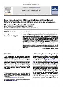
Figure 1. (a) As-forged compressor disc with an outer diameter of 320 mm and a maximal thickness of 26 mm. (b) Cross section of the disc with the location of the neutron measurements (line M). The points indicate the location of the tips of the thermocouples, which were inserted into drilled holes from the bottom side of the disc (K1 - K5).
518
Table 1: Nominal chemical composition of IN718. The remaining 0.5 wt% are small alloy additions (Co, Mn, Si, C) or impurities (P, S, Cu).
Ni
Cr
Fe
Nb
Mo
Ti
Al
wt %
52.5
19.0
18.5
5.1
3.0
0.9
0.5
at %
51.7
21.1
19.1
3.2
1.8
1.1
1.1
Figure 2. Microstructure of IN718 after forging and water quenching. The bright particles are δ precipitates, which are not dissolved during the forging process.
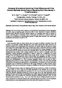
Temperature Measurements In this study the whole compressor disc was used to measure the temperature development during water quenching in order to simulate real industrial conditions. Coated K-type thermocouples (NiCr-Ni) with a diameter of 1.5 mm ensured a low reaction time of the thermocouples of < 1 sec. In order to avoid measurement artifacts due to vesication at the beginning of the quenching process, the tips of the thermocouples have not been attached to the surface. Instead each thermocouple was placed into a hole with a diameter of 1.5 mm and mechanically fixed to prevent any water flow into the hole (Fig. 1b). The tips of the thermocouples K1 to K5 were placed 3 mm below the sample surface, only K2 was placed 8 mm below the surface in the middle of the thicker part near the rim. The forged disc with the thermocouples was heated to forging temperature and subsequently quenched into water (20°C). In order to minimize the amount of bubbles formed due to the Leidenfrost effect, the disc was submerged in an upright position. The temperature recorded as a function of time is shown in Fig. 3. The timescale in Fig. 3 starts when the whole disc is still at forging temperature, thus sets the beginning of the quench to t = 10 sec, in order to better display the retarding drop in temperature at the beginning of cooling.
519
K1
1000
K2
K3
900
K5
Temperature [°C]
950
800 700
Temperatur [°C]
K4
600
900 850
500
800
400
750 6
300
8 10 12 14 16 18 20 22 24 Time [s]
200 100 0 0
20
40
60
80
100
120
140
160
180
Time [s] Figure 3. Measured temperature at the positions K1 - K5 inside the compressor disc (see Fig. 1b) during quenching in 20°C cold water. The inset shows the first 20 seconds in an expanded scale.
Neutron Diffraction As the distortion of the disc due to material removal, e.g. by turning, is governed by bulk residual stresses, neutron diffraction is the only available technique to measure strains within a part having a thickness of several cm. The measurements, using the whole disc, were conducted at the diffractometer ARES at GKSS, Germany [6]. A constant wavelength of 0.164 nm was used to monitor the distance of the (311) lattice planes as a function of the position within the disc [7]. The (311) reflection was chosen, because it is generally recommended in literature [8, 9] for the measurement of macrostresses in fcc materials. The spatial resolution of the strain measurement was determined by the 2x2x30 mm³ gauge volume (respectively 2x2x10 mm³ for the tangential direction). Measurements of the strain free reference sample were done on cuboids with a size of 4x4x4 mm³, which were cut from the disc by electro-discharge machining at the positions of the strain measurement (indicated by line M in Fig. 1b) [10]. The lattice spacing of these cuboids was determined in 3 directions to clarify if any remaining texture could influence the residual stress measurements. However, the lattice spacing were equal within the measurement error, which can be derived from the quality of the peak fitting function and, therefore, the average value was used for calculation of strains. This is consistent with microscopical observations and texture measurements by electron back scatter diffraction and neutron diffraction, all showing a nearly perfect random texture (max. 1.4 above random). Having determined the strains by applying Bragg’s law, the stresses can be calculated using the generalized Hook equation [11]. The axi-symmetric form of the disc suggests that the axial, radial and tangential direction determine the orientation of the main stress components. However, it has to be carried in mind that in single peak analysis specific diffractometric elastic constants for the (311) reflex have to be used. E311 and ν311 were determined to be 195000 MPa and 0.31, respectively, by employing the Kröner model [8]. As the turning operation removes material from the top and the bottom side of the disc, the residual stresses along the thickness of the disc will relax and can potentially cause distortions. Therefore, the points of neutron measurement were arranged along the thickness of the disc, indicated as line “M” in Fig. 1b.
520
Finite Element Modeling The software package DEFORM™ was used to simulate the forging process and the subsequent cooling step of the compressor disc shown in Fig. 1. Measured thermophysical data of IN718 showed a good agreement with published data in literature [12, 13, 14] and were applied to simulate both forging as well as cooling. Contrary, the flow stress curves are different for the forging and the quenching simulation, because forging simulations assume plastic material behavior and very high strain rates, whereas cooling is calculated with elasto-plastic material behavior. All flow stress curves were experimentally determined at different temperatures and strain rates. Since the heat transfer coefficient cannot be measured directly, first simulations used a constant value of c = 4000 W/m²K [15], which is based on data for water given in literature [16]. As a first approximation this value was assumed to be constant during the whole cooling procedure and was applied as a boundary condition on the entire surface of the disc. That means that at every point on the surface the same amount of heat is transferred into the cooling water. Detailed descriptions of the input data and the results of the simulation are described in [15]. In the present work, the influence of a variation of the heat transfer coefficient c on the residual stress state was studied. As c has been proven to be a very crucial input parameter, the measured temperatures during quenching within the disc were used to calibrate this value. To this end the temperatures at the five points K1 - K5 (Fig. 1b) were compared to the temperature development at the corresponding points in the FE simulations using different values or courses for c. Fig. 4a presents the temperature at point K3 as a function of time versus the simulated temperatures for different heat transfer coefficients, assuming that the cooling medium has a temperature of 20°C throughout the entire cooling process. As the effects during the early stages of the cooling (Fig. 3) cannot be described by a constant value of c, an offset of 6 sec was applied to the timescale of the simulated temperatures. Fig. 4b shows the experimental and simulated temperatures at all five measurement points as a function of time for a simulation performed with a constant value of c = 4000 W/m²K. As in reality the heat transfer is a function of the temperature difference between the cooling medium and the metal surface [17], further parameter studies have been performed with coefficients changing with time and temperature, respectively. Two examples of a simple variation of the heat transfer coefficient with time are shown in Table 2. Case c1 starts with mild cooling, while in case c2 a very short rapid cooling interval is inserted. After the first 4 sec c1 remains at the high level of 8000 W/m²K until the end of the cooling, whereas c2 is reduced stepwise. If a simple geometry with defined surfaces is modeled, then analytical calculations can be carried out to determine the heat transfer coefficient as a function of the measured temperatures inside a part. For example, this was done by Bucezek at al. [18] on a cylinder made of brass. As the materials are different, their results cannot be applied for the present study, however, the general course of their heat transfer coefficient was adopted (c3; Fig. 5a) and improved the fit of our measured temperature curves.
521
1000
1000
700 600 500 400
800
300
700 600 500 400 300
200
200
100
100
0
(a)
measured: FEM: K1 c=4000 W/m²K: K2 K1 K3 K2 K4 K3 K5 K4 K5
900
1000 2000 3000 4000 5000 6000 8000 10000
Temperature [°C]
800
Temperature [°C]
FEM c - values:
measured at point K3
900
0 0
5
10
15
20
25
30
35
40
45
50
55
60
Time [s]
(b)
0
5
10
15
20
25
30
35
40
45
50
55
60
Time [s]
Figure 4. a) Temperature at K3 as a function of time for different heat transfer coefficients. The bold line represents the measured temperature at point “K3” (Fig. 3). b) Measured and calculated temperatures at the five measurement positions K1 – K5 (Fig. 1b). Simulation performed with a constant heat transfer coefficient of 4000 W/m²K. Table 2: Heat transfer coefficients assumed for cooling in water taking the Leidenfrost effect into account.
Case c1 c2
0-1s 60 8000
1-4s
4 - 40 s
40 - 70 s 70 - 120 s 8000 8000 3000 2000
60
Results and Discussion The temperatures of the 4 thermocouples (K1, K3, K4, K5) near the upper surface of the disc show a period of slow cooling during the first 4 sec, followed by a large drop of temperature in the next 40 sec and finally a marked reduction of the cooling velocity (Fig. 3). After 120 sec the whole part has cooled down close to the temperature of the cooling agent (water, 20°C). The initial period of slower cooling can be interpreted as a consequence of the Leidenfrost effect, because the thermocouple placed in the center of the disc (K2) does not show this change of the cooling velocity in the first seconds. If a constant heat transfer coefficient is used for the simulation, there is always a steady decrease in temperatures with time, therefore, the first 10 sec cannot be modeled correctly (Fig. 4a). However, the slope of the measured temperature curves between 850°C and 150°C at K1 - K5 is well reflected by the simulated temperature curves resulting from a constant heat transfer coefficient of approximately 4000 W/m²K which has been used in the first calculations [15]. The comparison of the resulting radial and tangential stresses with the measured stresses in Fig. 6 demonstrates that 4000 W/m²K is an appropriate estimation of the heat transfer coefficient. For a further adjustment of the cooling curves, a short period of milder cooling conditions can be introduced during the first 4 sec, followed by a higher quenching rate. Indirectly, this offers the possibility to take the nucleation of air bubbles or the presence of an air film into account, which reduces the heat transfer locally until the bubbles or the film collapse and the whole surface of the disc is in contact with liquid water. Furthermore, the slower drop of all temperatures at about 300°C indicates that the heat transfer is reduced towards the end of the cooling process, because the temperature difference between the water and the surface becomes smaller.
522
measured at point K3
900
14000
800
12000
Temperature [°C]
Heat Transfer Coefficient [W/m²K]
1000
16000
10000 8000 6000 4000
700 600 500 400 300 200
2000
100
0 0
(a)
FEM c - values: c = 4000 c1 (Time) c2 (Time) c3 (Temp)
200
400
600
800
Temperature [°C]
1000
1200
0
1400
0
(b)
5
10
15
20
25
30
35
40
45
50
55
60
Time [s]
Figure 5. Variation of the heat transfer coefficient c3 (a) and the resulting temperature at point K3 (b). The variation of c1 and c2 are listed in Table 2.
When a constant heat transfer coefficient is used, the radial and tangential stress maxima (Fig. 6) evolving during quenching do not further change significantly above c = 10000 W/m²K. Applying higher values of c would result in a too fast decrease of the temperature. Comparing the measured stresses and the simulated results, approximately 5000 W/m²K can be regarded as the upper bound, if a constant c value is used in the simulation. On the other hand, a value of 2000 W/m²K has shown to be the lower bound to fit the measured temperature curves (Fig. 4a). With rising quenching rates not only the maximum stress levels but also the trend of the stress curves change, because the horizontal region of zero residual stress in case of 2000 W/m²K becomes less pronounced and finally diminishes as the heat transfer rises (Fig. 6). This can be attributed to the occurring plastic flow, which becomes larger and thus affects larger regions of the cross section, depending on the prevailing temperature gradient. Qualitatively, this can also be shown by analytical calculations of a quenched plate [5]. The strain measurements do not reflect this change in the slopes, because the gauge volume of 2x2x2 mm³ is too large and, therefore, the values represent an average stress at the location of the measurement. For a discussion of the exact shape of the stress gradients a higher lateral resolution of the measured strains would be required. Yet, the distance of the point where the radial and tangential stresses cross zero can be compared and have shown to be the same for the measurement and simulation. The fact that the measured points are shifted approximately 1 mm to the top side of the disc could be a consequence of asymmetric heat transfer conditions on top and bottom side. A systematic positioning error of the disc in the neutron beam, which might be another source of the observed shift, is highly unlikely, because the measured stress results were proven to be repeatable. Changing the heat transfer coefficient with time (Table 2) or as a function of surface temperature (Fig. 5a) affects the level of the maximum as well as the gradient of the stress curve across the thickness (Fig. 7). For instance, introducing a short period of a high heat transfer in the first seconds, followed by a short period of air cooling conditions which is then replaced by high cooling rates again (Version c2, Table 2), results in a broader stress curve along the cross section of the disc as shown in Fig. 7. By varying c as a function of the surface temperature it seems realistic to use values of up to 14000 W/m²K temporarily because a good approximation of the measured temperature drops at the locations K1 to K5 is achieved. Fig. 5a shows the applied heat transfer coefficient as a function of temperature and Figs. 7a, b display the resulting radial and tangential stresses. Now,
523
the maximum stress levels are below the one obtained for the upper bound for a constant heat transfer coefficients of 5000 W/m²K, although the maximum c is much higher (Fig. 7, c3).
Radial Stress
Tangential Stress
800 measured
measured
Residual Stress [MPa]
600 FEM - c values: 1000 2000 3000 4000 5000 6000 8000 10000
400 200 0 -200 -400 -600 0
2
4
6
8
10
12
14
0
Vertical Distance [mm]
(a)
2
4
6
8
10
12
14
16
Vertical Distance [mm]
(b)
Figure 6. Simulated (a) radial and (b) tangential stresses at a disc radius of 100 mm assuming constant heat transfer coefficients c (given in W/m²K). The axial stresses are zero for all cooling conditions. The symbols indicate the stress values determined by neutron diffraction (measurement error approximately ± 50 MPa).
Radial Stress
Tangential Stress
800 measured
measured
Residual Stress [MPa]
600 FEM - c values: 1000 2000 3000 4000 5000 6000 8000 10000
400 200 0 -200 -400 -600 0
(a)
2
4
6
8
10
12
Vertical Distance [mm]
14
0
(b)
2
4
6
8
10
12
14
16
Vertical Distance [mm]
Figure 7. Simulated residual stresses using a constant heat transfer coefficient of 4000 W/m²K. A heat transfer coefficient varying with time (c2, Table 2) or with temperature (c3 in Fig. 5a): (a) radial and (b) tangential stresses along the cross section of the disc. The symbols indicate the stress values determined by neutron diffraction (measurement error approximately ± 50 MPa).
524
The measured maximum stress levels seem to be about 150 - 200 MPa higher than the simulated stresses. This indicates that for a further improvement of the fit quality, the heat transfer coefficient in Fig. 5a should temporarily be increased even above 14000 W/m²K. This result is also confirmed by studies in literature. For example, Dye et al. [19] made inverse calculations to estimate the heat transfer coefficient of an IN718 cylinder in different quenching media and reported values up to c = 30000 W/m²K. Nevertheless, with raising heat transfer coefficients the calculated temperatures at K1 – K5 drop too fast. For example, the variable heat transfer coefficient shown in Fig. 5a as well as a constant value of c = 4000 W/m²K result in cooling rates which are slightly too fast. Consequently, a realistic description of the temperature can only be achieved by a very careful increase of the heat transfer coefficient combined with well chosen smaller values at the start and towards the end of the cooling process. Summary and Conclusions Finite element simulations and neutron diffraction measurements of the residual stress state in a compressor disc made of IN718 after quenching in water have been performed. The same FEM code, DEFORM™, has been employed to simulate the forging process as well as the quenching procedure. The aim of the present study was an experimental verification of the cooling simulation. Especially the evolution of the heat transfer coefficient was of prime importance, because it has a significant influence on the residual stress state after quenching. However, the heat transfer coefficient is the only material input data that can not be measured directly, therefore, parameter studies have been carried out to clarify its influence. Additionally, the temperatures within the disc have been measured at 5 positions during quenching in water. These two independent sets of experimental data indicated an lower and upper bound of 2000 to 5000 W/m²K for a constant heat transfer coefficient. Although in reality the heat transfer is not constant, but depends on the surface and water temperature, a constant value of 4000 W/m²K seems to give a good approximation to simulate the evolution of the residual stress state. Allowing the heat transfer coefficient to vary with time or surface temperature offers the possibility of an improved fit of the measured temperatures. Theses changes have an effect also on the maximum stress levels and especially on the shape of the stress gradient. It seems that the heat transfer coefficient can momentarily be much higher than 5000 W/m²K. Temporarily values above 14000 W/m²K combined with moderate conditions at the beginning and towards the end lead to a better fit of the measured temperature curves. The results suggest that the simulation can be further improved by an adopted temperature dependent heat transfer coefficient. Nevertheless, also a constant value of 4000 W/m²K leads to a good prediction to the independently measured residual stresses and temperatures. Literatur 1. W. Betteridge, Materials Science and Technology, VCH, Weinheim, New York, Basel, Cambridge 7 (1992) 641. 2. E. Brown and D.R. Muzyka, Superalloys II, (New York, Chichester, Brisbane, Toronto, Singapore; Wiley, 1987), 165 - 188. 3. W. Horvath et al., “The Effectiveness of Direct Aging on INCONEL718 Forgings Produced at High Strain Rates as Obtained on a Screw Press “, Superalloys 718, 625, 706 and Derivates, TMS (2001), 223 - 228.
525
4. J. Tockner, W. Horvath, and J. Fladischer, “Simulationsunterstützte Optimierung des Umformens auf Spindelpressen”, BHM, 146 (9) (2001), 392 - 395. 5. C. Krempaszky, E.A. Werner, and M. Stockinger, “Residual Stresses in IN718 Turbine Disks” (paper presented at the Superalloys IN718 & Derivates 2005). 6. P. Staron et al., “The New Diffractometer ARES for the Analysis of Residual Stresses“, Physica B, 276 – 278 (2000), 158 - 159. 7. T.M. Holden, C.N. Tomé, and R.A. Holt, “Experimental and Theoretical Studies of the Superposition of Intergranular and Macroscopic Strains in Ni-based Industrial Alloys”, Metall. Mater. Trans. A, 29 (1998), 2967 - 2973. 8. D. Dye et al., “The Determination of the Residual Strains and Stresses in a Tungsten Inert Gas Welded Sheet of IN718 Superalloy Using Neutron Diffraction”, J. Strain Analysis, 35 (4) (2000), 247-259. 9. V. Hauk, Structural and Residual Stress Analysis by Nondestructive Methods (Amsterdam: Elsevier, 1997). 10. A.D. Kravitz and R.A. Winholtz , “Use of Position-Dependent Stress-Free Standards for Diffraction Stress Measurements”, Mater. Sci. Eng. A, 185 (1994), 123 – 130. 11. A.J. Allen et al., “Neutron Diffraction Methods for the Study of Residual Stress Fields”, Advances in Physics, 34 (1985), 445 - 473. 12. G. Pottlacher et al., “Thermophysikalische Eigenschaften von festem und flüssigem INCONEL718”, Thermochimica Acta, 382 (2002), 255 - 267. 13. W. Mitter, “Optimization of Complex, Cost- and Quality-Relevant Production Parameters of Precession Forged Turbine Blades by the Use of Computer Simulation” (Final Technical Report Boehler Schmiedetechnik GmbH & CoKG, Kapfenberg, Austria, 1996). 14. K.C. Mills, “Recommended Values of Thermophysical Properties for Selected Commercial Alloys”(Report NPL, Woodhead Publishing Limited, Cambridge, UK, 2002), 181 190. 15. U. Cihak et al., „Residual Stresses in Forged IN718 Turbine Discs”, Zeitschrift für Metallkunde 95 (7) (2004), 663 - 667. 16. H. Chandler, Heat Treater’s Guide (ASM International, Materials Park, Ohio, USA, 1995), 88. 17. S. Nukiyama, “The Maximum and Minimum Values of the Heat Q Transmitted from Metal to Boling Water Under Atmospheric Pressure”, J. Heat Mass Transfer, 9 (1966), 1419 1433. 18. A. Buczek and T. Telejko, “Inverse Determination of Boundary Conditions During Boiling Water Heat Transfer in Quenching Operations “, J. Mat. Proc. Tech.. 155 - 156 (2004), 1324 - 1329. 19. D. Dye, K.T. Conlon, R.C. Reed, “Characterization and Modelling of Quenching Induced Residual Stresses in the Nickel-Based Superalloy IN718”, Met. Mat Trans A 35A (2004), 1703 1713.
526


![free [download] finite element simulations with ansys ... - Google Sites](https://m.moam.info/img/260x300/free-download-finite-element-simulations-with-ansy_6478ad6a097c474d228d6b1c.jpg)