Feb 7, 2018 - is free from contamination (by not using oil as a sealing element), and ... One of the face of the seal has spiral grooves and the opening force ...
American Journal of Aerospace Engineering 2017; 4(5): 54-58 http://www.sciencepublishinggroup.com/j/ajae doi: 10.11648/j.ajae.20170405.11 ISSN: 2376-4813 (Print); ISSN: 2376-4821 (Online)
Numerical Computation of Flow Field in the Spiral Grooves of Steam Turbine Dry Seal Juan Carlos Garcia, Ricardo Reyes Hernández*, Oscar De Santiago Duran, José Alfredo Rodríguez Ramirez, Fernando Sierra Espinosa, Miguel Basurto Pensado Faculty of Chemical Science and Engineering, Center for Engineering and Applied Sciences, Autonomous State University of Morelos, Morelos, Mexico
Email address: *
Corresponding author
To cite this article: Juan Carlos García, Ricardo Reyes-Hernández, Oscar De Santiago, José Alfredo Rodríguez, Fernando Sierra-Espinosa, Miguel Basurto. Numerical Computation of Flow Field in the Spiral Grooves of Steam Turbine Dry Seals. American Journal of Aerospace Engineering. Vol. 4, No. 5, 2017, pp. 54-58. doi: 10.11648/j.ajae.20170405.11 Received: November 13, 2017; Accepted: December 1, 2017; Published: February 7, 2018
Abstract: Steam turbines, like other turbo-engines, require sealing elements, which prevent the working fluid escape outside of the turbine, causing power losses and environmental contamination. In this work the Flow Field in Spiral Grooves of Steam Turbine Dry Seals was determined using Computational Fluid Dynamics (CFD). The dry seal considered in this study has spiral grooves on the moving face. The flow field was computed for two different spiral groove inlet angle configurations (13 and 15 degrees). Additionally the opening force caused by the effect of the interaction of the rotational speed of the grooves and flow field was determined. Among the results it was found that the opening force generated on the seal walls is proportional to the opening angle of the spiral grooves. The spiral groove inlet angle of 15° generated major opening force.
Keywords: Flow Field, Spiral Grooves, Dry Seal, Turbine, Computational Fluid Dynamics
1. Introduction Dry seals are used in turbomachines, which can be found in the power generation industry and also in the aeronautic industry. Dry seals are not the only sealing system available for turbomachines, however they have the advantages of reducing working fluid leaks and long service life [1, 2, 3]. Other advantages of the dry seals are: the turbine working fluid performs lubrication on the seal faces, the working fluid is free from contamination (by not using oil as a sealing element), and there is no contact between the seal faces under operating conditions so there is a minimal friction with the working fluid [9]. For the design of a sealing system that uses dry gas seal, the basic problem is to determine the flow field in order to know the opening force that can be provided by the seal in rotation at the turbine operation speed. With this opening force, the mechanical design of the seal could be proposed so that the faces of the dry seal have to open only 1 to 5 microns. By increasing the speed of rotation of the seal, the
seal pressure value has an increment by the interaction of the seal grooves with the working fluid, and it has also been found that leakage also increases, but with an insignificant value [4, 5]. When the seal is not moving, the opening force is zero, so the gap between the dry seal faces is also zero. One of the faces a dry seal has grooves with different geometrical forms like: spiral, radial, tree, T shape, etc. Some researchers like Ochiai M. et al. presented a topological optimization of groove shapes resolving the Reynolds equivalent equation to determine the static and dynamic characteristics of the seal [6]. Ma F. et al. showed that increasing the number of grooves in 30, the seal reached greater opening forces [7]. Chen X. et al. resolved compressible Reynolds equation to compute tracking properties of dry gas seal using different groove geometries [8]. In this work the flow field in the seal and the opening forces were determined by Computational Fluid Dynamics (CFD). One of the face of the seal has spiral grooves and the opening force was computed for grooves with different inlet angle: 13° and 15°. During CFD computation the Spalart-
55
Juan Carlos Garcia et al.: Numerical Computation of Flow Field in the Spiral Grooves of Steam Turbine Dry Seal
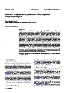
Θ = arc angle between grooves. β = spiral groove inlet angle angle (13 and 15 degrees)
Allmaras turbulence model was used.
2. Method
Table 1. Dry gas seal geometric dimensions.
The flow field inside the dry seals and the opening forces generated during the dry seal operation were calculated using Computational Fluid Dynamics (CFD). The CFD methodology for dry seals is described below. 2.1. Geometry The main dimensions of the dry seal geometry are shown in Table 1. Two geometric models of the dry seal with different spiral groove inlet angle were developed.
Groove depth Gap between seal faces Outer radius Inner radius Inner groove radius Arc angle between grooves Grooves
5x10⁻⁶m 5x10⁻⁶m 64.20x10⁻³m 45.87x10⁻³m 55.03x10⁻³m 36 10
The opening force on the seal walls, as well as the flow field, was calculated for two geometric models of seals where the inlet angle (β) of spiral groove was changed (β=13º and β=15º). Figure 2 shows a tenth of the seal domain which was created using ICEM. The coordinates of spiral groove were calculated with the equation 1. Only one tenth of the seal geometry was created, because the seal has circumferential periodicity. A hybrid meshing was created, combining a structured with a tetrahedral mesh, with 504604 cells. The minimum cell volume was 2.3 x10⁻¹⁵ m3 and the maximum cell volume was 1.94x10⁻¹⁴ m3. In order to facilitate the meshing task, the seal domain was divided in 6 regions (Figure 3). In every region was meshed with a different element type as indicated in Table 2. A view of a meshed area of a dry seal face is shown in Figure 4.
Figure 1. Schematic of the grooved face of a dry gas seal.
Figure 3. Domain structure split in regions for meshing. Table 2. Meshing elements types per region. Region domain 1 2 3 4 5 6
Figure 2. A tenth of the dry gas seal domain.
Mesh/Area Quad-Map Quad-Map Quad-Map Tri-Pave Tri-Pave Tri-Pave
Mesh/Volume Map (Hex) Map (Hex) Map (Hex) Cooper Cooper Cooper
Figure 1 shows a schematic of the dry gas seal with spiral grooves, where the angle β indicates the inlet angle of the spiral groove towards the center. The spiral groove is described by (1) [10, 11].
r = R gi e θ tan β Where: Rgi = inner groove radius
(1) Figure 4. Mesh view of a dry seal face.
American Journal of Aerospace Engineering 2017; 4(5): 54-58
56
obtained, it was chosen a mesh of 500,000 cells.
2.2. Numerical Calculation with FLUENT The meshed dry seal domain was exported to Fluent, where the Reynolds Averaged Navier Stokes and energy equations were solved. The boundary conditions types are shown in Figure 5. To deal with turbulence the SpalartAllmaras turbulence model was used. The convergence criteria for continuity and momentum equations was a residual value of 0.001 and for energy of 1 x10-06. As the dry seal investigated in this paper will be used in a steam turbine, the thermodynamic conditions of the working fluid (steam) at inlet are showed in Table 3.
3. Results All the flow field were resolved for 500, 1800, 3600 and 7200 rpm. Data were obtained from a plane generated in the middle of the flow field between the seal walls. The velocity vectors in that plane is shown in Figure 6.
Figure 6. Velocity vectors for dry seal with β= 13º rotating at 7200 rpm
3.1. Results for the Case of Dry Gas Seal with Inlet angle β=13º
Figure 5. Boundary conditions type for the dry seal domain. Table 3. Boundary conditions for the dry gas seal inlet and outlet. Inlet conditions (Pent; ρent; µent) Outlet conditions (Psal)
Figures 7 through 10 show the static pressure contours for a middle plane in the dry seal domain.
490,332 Pa man, 1.78 Kg/m3, 26.5778 µPas 0 Pa man
The opening force and flow field were determined for the 13 and 15 spiral groove inlet angle for 500, 1800, 3600 and 7200 rpm. The computations were performed in a transient state, where the time step was 0.0005 seconds. For CFD computations, the time step was calculated using (2), (3) and (4). Tangential Speed Vt =
( w ) ( rext )
(2)
Length of arc of each segment L=(2πr)/(grooves)
(3)
Figure 7. Static pressure contour for 500 rpm, β= 13º..
Total step size Temporary ∆t=L/(10Vt)
(4)
Calculations were performed using an Intel (R) Xeon (R) CPU E5620 processor. 2.40 GHz speed. 16 GB RAM memory. 64 bit operating system. 2.3. Mesh Convergence Study. A mesh convergence study was performed to demonstrate mesh independence. In this study pressure was used as a variable to determine the independence of cell size. The geometry was discretized varying the number of cells, using 108573 cells, 490230 cells and 873814 cells. From the results
Figure 8. Static pressure contour for 1800 rpm, β= 13º.
57
Juan Carlos Garcia et al.: Numerical Computation of Flow Field in the Spiral Grooves of Steam Turbine Dry Seal
Figure 12. Static pressure contour for 1800 rpm, β= 15º. Figure 9. Static pressure contour for 3600 rpm, β= 13º.
Figure 13. Static pressure contour for 3600 rpm, β= 15º.
Figure 10. Static pressure contour for 7200 rpm, β= 13º.
It was observed from Figures 7, 8, 9 and 10 that when the rotation speed is increased, also the static pressure is increased in the domain. The largest pressures are at the entrance of the seal and in the groove (pressures between 399,000 to 490, 332 Pa). There are medium pressures at the middle of the seal, pressures of 200,000 to 399,000 Pa and low pressures at the exit of the seal (28500 to 200,000 Pa). Figure 14. Static pressure contour for 7200 rpm, β= 15º.
3.2. Results for the Case of Dry Gas Seal with Inlet Angle β=15º Figures 11 through 14 show the static pressure contours for a middle plane in the dry seal domain for dry seals with a spiral groove inlet angle of 15º.
It was observed from Figures 11, 12, 13 and 14 the behavior in the domain for the input angle value of 15 degrees is very similar to the angle of 13 degrees. The largest pressures are at the entrance of the seal and in the groove, pressures of 399,000 to 490, 332 Pa and the pressure are reducing, due to the restriction that represents the microchannel, there are medium pressures at the middle of the seal, pressures of 200,000 to 399,000 and very low pressures at the exit of the seal, pressures of 28500 to 200,000 Pa. However, the static pressure values increasing for the opening angle of 15 degrees, this is due to the greater mass of fluid entering the groove of the dry seal and the groove is the place where the highest values of static pressure are present. 3.3. Opening Force Calculated by CFD on the Stationary Face of the Seal, for Each Inlet Angle of the Spiral
Figure 11. Static pressure contour for500 rpm, β= 15º.
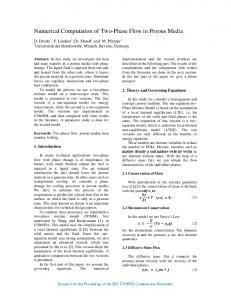
Figure 15 shows the opening force on the seal walls generated by hydrodynamic pressure caused by the
American Journal of Aerospace Engineering 2017; 4(5): 54-58
interaction of the groove with the fluid. The opening force is increasing when the speed of rotation are increasing too, however it is always greater for the opening angle of 15 degrees.
References [1]
B. Wang, “Numerical Analysis of a Spiral-groove Dry-gas Seal Considering Micro-scale Effects,” Chinese J. Mech. Eng., vol. 24, no. 01, p. 146, 2011.
[2]
S. Li, Q. Zhu, J. Cai, Q. Zhang, and Z. Jin, “Regulation Performance of Regulatable Dry Gas Seal,” vol. 11, pp. 18– 24, 2016.
[3]
B. Wang, H. Zhang, and H. Cao, “Flow dynamics of a spiralgroove dry-gas seal,” Chinese J. Mech. Eng., vol. 26, no. 1, pp. 78–84, Feb. 2013.
[4]
Y. Li, P. Y. Song, and H. J. Xu, “Performance Analyses of the Spiral Groove Dry Gas Seal with Inner Annular Groove,” Appl. Mech. Mater., vol. 420, pp. 51–55, Sep. 2013.
[5]
J. Xu, X. Peng, S. Bai, X. Meng, and J. Li, “Experiment on wear behavior of high pressure gas seal faces,” Chinese J. Mech. Eng., vol. 27, no. 6, pp. 1287–1293, Oct. 2014.
[6]
M. Ochiai, H. Sasaki, Y. Sunami, and H. Hashimoto, “Topological Optimization of Dry Gas Seals for Improving Seal Characteristics,” pp. 196–200, 2014.
[7]
F. B. Ma, P. Y. Song, and J. Gao, “Numerical Analysis of Radial Groove Gas-Lubricated Face Seals at Slow Speed Condition,” Adv. Mater. Res., vol. 468–471, pp. 2304–2309, Feb. 2012.
[8]
C. Xu, W. F. Huang, and X. F. Liu, “Tracking Property Analysis of a Dry Gas Seal Operating in Low Pressure Condition,” Appl. Mech. Mater., vol. 532, pp. 367–373, Feb. 2014.
[9]
W. F. Xu, X. H. Li, and G. Ma, “A Method of Dual Number for the Aerodynamic Property Analysis of Gas-Lubricated Mechanism: Self-Pressurizing Thrust Bearings and NonContacting Face Seals,” Adv. Mater. Res., vol. 311–313, pp. 360–369, Aug. 2011.
Figure 15. Opening force on seals with spiral grooves.
4. Discussion When the dry seal face with spiral grooves is rotating, the radial profiles show that the pressure generated inside the seal domain is greater than the inlet pressure, blocking the flow to the outlet. The pressure and the opening force increase as the rotation speed of seal face is increasing. The results show that the spiral groove inlet angle affect the performance of the dry seal, in such way that the pressure and the opening force is bigger for inlet angle of 15 degrees.
5. Conclusions The flow field in the domain of the dry seal was computed using CFD using the Spalart Allmaras turbulence model. Using the pressure on the dry seal walls, the opening forces were calculated for each of the dry seal geometries. The dry gas seal with a 15 degrees angle at the inlet of the spiral groove always generated a greater opening force compared to the dry gas seal with spiral of 13 degrees of the spiral groove. The results shown that the opening force always is increased as the rotational speed of grooved seal face is increased. The interaction of the flow field with the rotation of the grooved seal face cause a pressure increase in the seal domain causing an opening force and blocking the flow across the seal.
Acknowledgements This study was supported by National Council of Science and Technology (CONACYT). Projects 206393 and 280878.
58
[10] F. Sealing, “An Improved Design of Spiral Groove Mechanical Seal,” vol. 15, no. 4, pp. 499–506, 2007. [11] J. Bin Hu, W. J. Tao, Y. M. Zhao, and C. Wei, “Numerical Analysis of General Groove Geometry for Dry Gas Seals,” Appl. Mech. Mater., vol. 457–458, pp. 544–551, Oct. 2013. [12] I. Shahin, M. Gadala, M. Alqaradawi, and O. Badr, “Centrifugal Compressor Spiral Dry Gas Seal Simulation Working at Reverse Rotation,” Procedia Eng., vol. 68, no. July 2016, pp. 285–292, 2013. [13] I. Shahin, “Dry Gas Seal Simulation with Different Spiral Tapered Grooves Dry Gas Seal Simulation with Different Spiral Tapered Grooves,” no. January 2014, 2016. [14] I. Shahin, M. Gadala, M. Alqaradawi, and O. Badr, “Three Dimensional Computational Study for Spiral Dry Gas Seal with Constant Groove Depth and Different Tapered Grooves,” Procedia Eng., vol. 68, no. July 2016, pp. 205–212, 2013. [15] X. P. Hu and P. Y. Song, “Theoretic Analysis of the Effect of Real Gas on the Performance of the T-Groove and Radial Groove Dry Gas Seal,” Appl. Mech. Mater., vol. 271–272, pp. 1218–1223, Dec. 2012.