IOP Conference Series: Earth and Environmental Science
PAPER • OPEN ACCESS
Numerical Simulation of Bottomhole Flow Field Structure in Particle Impact Drilling To cite this article: Weidong Zhou et al 2018 IOP Conf. Ser.: Earth Environ. Sci. 108 032080
View the article online for updates and enhancements.
This content was downloaded from IP address 185.158.103.228 on 31/01/2018 at 00:30
ESMA 2017 IOP Conf. Series: Earth and Environmental Science1234567890 108 (2017) 032080
IOP Publishing doi:10.1088/1755-1315/108/3/032080
Numerical Simulation of Bottomhole Flow Field Structure in Particle Impact Drilling Weidong Zhou, Jinsong Huang and Luopeng Li School of Petroleum Engineering, China University of Petroleum (east China) *Corresponding author e-mail:
[email protected] Abstract. In order to quantitatively describe the flow field distribution of the PID drilling
bit in the bottomhole working condition, the influence of the fluid properties (pressure and viscosity) on the flow field of the bottom hole and the erosion and wear law of the drill body are compared. The flow field model of the eight - inch semi - vertical borehole drilling bit was established by CFX software. The working state of the jet was returned from the inlet of the drill bit to the nozzle outlet and flowed out at the bottom of the nozzle. The results show that there are irregular three-dimensional motion of collision and bounce after the jetting, resulting in partial impact on the drill body and causing impact and damage to the cutting teeth. The jet of particles emitted by different nozzles interfere with each other and affect the the bottom of the impact pressure; reasonable nozzle position can effectively reduce these interference.
1. Introduction In order to solve the difficult problem of drilling hard rocks and strong abrasive formation in drilling engineering, the rock breaking technology can be effectively solved as the advanced drilling technology [1]. PID drill bit is one of the important components of particle jet rock breaking technology, PID drill bit using high-pressure jet carrying high hardness, high abrasive steel, with high speed and frequency impact of the formation of broken rock [2], by reducing the rock breaking critical pressure to improve the strong abrasive formation and deep hard layer of the mechanical drilling rate [3]. 2. Mathematical Description The conditions for the internal and external flow fields of the PID drill are set as: (1) the input of the drill inlet and the mud is uniform and stable; (2) the default bottom hole shape is regular and does not deform [4]; (3) the particle size of the inner and outer flow field of the PID drill bit is set as follows: (4) The movement state of the drill bit is constant rotation of the constant angular velocity, and does not shift in the horizontal direction and the vertical direction. From the above conditions, the internal and external flow field of the PID drill bit is set as a stable incompressible turbulent flow field, and the turbulence model can be used as a turbulence model [5]. In the relative Cartesian coordinate system that rotates around the axis at constant angular velocity, the continuity equation is [6]:
Content from this work may be used under the terms of the Creative Commons Attribution 3.0 licence. Any further distribution of this work must maintain attribution to the author(s) and the title of the work, journal citation and DOI. Published under licence by IOP Publishing Ltd 1
ESMA 2017 IOP Conf. Series: Earth and Environmental Science1234567890 108 (2017) 032080
IOP Publishing doi:10.1088/1755-1315/108/3/032080
( u j ) 0 t x j
( ui ) ( u j ui ) t u j
[ e (
ui u j )] x j xi x j
(1)
p Si xi
(2)
The effective viscosity coefficient is equal to the molecular viscosity coefficient plus the turbulent vortex viscosity coefficient t :
e t t C k
k2
uiuj 2
ui u j ( )( ) x j xi
(3)
(4)
(5)
(6)
The equation of turbulent kinetic energy and turbulence dissipation at high Reynolds number [7]:
k ( k ) ( ku j ) [( t ) ] ( Pk ) t x j x j k x j ( ) ( u j ) [( t ) ] (C1 Pk C2 ) t x j x j k x j Pk
t ui u j ui ( ) x j xi x j
(7)
(8)
(9)
The model constants are:
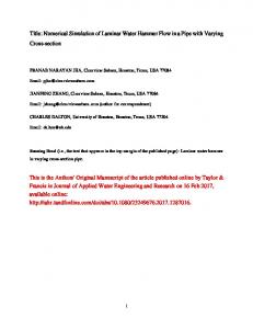
C 0.09,C1 1.44,C2 1.92, k 1.0, 1.3 3. Geometric model establishment and meshing 3.1. Geometric model establishment Select a 216BTM115A6 PID drilling bit as a geometric model, the solid model of the drilling bit is completed by Solidworks 2016 software, as shown in Figure 1.
2
ESMA 2017 IOP Conf. Series: Earth and Environmental Science1234567890 108 (2017) 032080
IOP Publishing doi:10.1088/1755-1315/108/3/032080
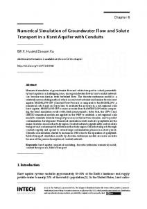
Figure 1. PID drilling bit’s geometry model 3.2. Meshing When the computational domain is meshed, the hybrid grid model is used to fit the complexity of the computational model. The cylindrical section at the entrance and the cylindrical section at the inner cavity adopt a structured grid. In the more complex position (near the nozzle, the outer flow field at the tip of the blade), the unstructured grid is used and localized. The grid is shown in Figure 2. This will not only meet the requirements of the calculation accuracy, but also to ensure the speed of operation.
Figure 2. PID bottomhole flow field’s meshing 3.3. Boundary conditions The entrance is the velocity inlet, the velocity direction is perpendicular to the inlet cross section, through the working displacement; the export is carried out with the pressure outlet, and the outlet boundary without the return flow is selected. The export section adopts the local unidirectional assumption; the wall condition adopts the wall function in the near wall area Method for the treatment, the use of non-slip boundary layer; medium using two-phase flow model, solid phase with the liquid phase transport follow. 4. Numerical simulation results and analysis 4.1. Analysis of Fluid Flow Field Structure The bottomhole flow field generated by the PID drill bit is similar to that of the conventional drill bit. It is divided into four parts: the free jet area, the bottomhole flow area, the reflux vortex area and the wall return area, Show. Since the working distance of the particle jet is higher than the distance from the bottom of the ordinary PDC bit, the flow field structure changes. As the two-phase flow state is very complex, so the two phases are described separately.
3
ESMA 2017 IOP Conf. Series: Earth and Environmental Science1234567890 108 (2017) 032080
IOP Publishing doi:10.1088/1755-1315/108/3/032080
Figure 3. PID fluid motion trajectory 4.1.1. Free jet area. After the five nozzles are accelerated, they are ejected from the outlet and spread at an angle. They reach the bottom of the well and are evenly distributed at different radii of the bottom of the well. Through the rotation of the drill head, the entire nozzle is covered and the particle jet reaches the bottom it is still possible to keep the critical pressure on rock breaking. Between the nozzle in the angle adjustment, a jet does not interfere with each other will not impact to the blade, causing damage to the blade. The flow pattern of the free jet zone can be used to calculate the working efficiency of the fluid at the bottom of the well. 4.1.2. Bottomhole flow area. After the particle jet reaches the bottom of the well, it does not rebound immediately, but diverges at the bottom of the well, and the jet pressure decreases rapidly and interferes with the other flows, and the flow is carried out along the extension of the jet at the bottom of the well Scatter and have a portion of the shunt after a brief spread. The flow pattern of the bottom flow area can be used as an important index to measure the area of the fluid in the bottom of the well. 4.1.3. Reflux vortex area. Particle jet after the bottom of the well and the wall after the rebound, and other nozzles jet fluid and the surrounding fluid momentum exchange, resulting in low-pressure vortex area. The radius and angle of the nozzle should be adjusted reasonably, avoiding collision and energy exchange in the vortex zone as much as possible, reducing the volume covered by the eddy current, allowing the respective return fluid to leave the vortex zone quickly and return along the borehole and drill bit side. The flow pattern of the recirculation vortex zone can be used as a pattern for analyzing the turbulent interference region of the fluid at the bottom of the well. 4.1.4. Wall return area. The setting of the helical blade and the improved chip flute allow the particle jet to be quickly retracted along the side wall. The drill bit is rotated at a constant angular velocity and the blade side is angled to facilitate the discharge of cuttings and particle jets. Allows the maximum space for the chip flutes while ensuring the nozzle exit position. The increase of the return speed is beneficial to reduce the influence of eddy current in the bottom flow field. The flow pattern of the return wall can be used as a basis for analyzing the efficiency of the drilling fluid carrying the cuttings.
4
ESMA 2017 IOP Conf. Series: Earth and Environmental Science1234567890 108 (2017) 032080
IOP Publishing doi:10.1088/1755-1315/108/3/032080
4.2. Analysis of Particle Motion Trajectory The trajectories of the particles are quite different from those of the streamlines. They can be divided into three regions: free impact area, catapult collision area and flow back area (Fig. 4).
Figure 4. PID particle motion trajectory 4.2.1. Free impact area. Particle energy is transferred by the drilling fluid, and after the nozzle is accelerated, the moving particles are ejected at high speed from the nozzle outlet. Figure 6 shows that the initial trajectory of the particle is substantially the same as the streamline, and that a jet generated between the nozzles does not strike the blade, does not interfere with each other before reaching the working face, and ensures that the critical rock breaking is achieved in the respective working area above the pressure. The particle trajectory of free impact zone can be used as an important index to measure the efficiency of particle breaking. 4.2.2. Catapult collision area. Particles in contact with the bottom of the hole, will rebound in different directions, and in the ejection of the way with other particles collide with the action of the vortex in the performance of the movement of the trajectory, part of the particles will hit the drill body. The particle trajectory of the catapult collision zone can be used to analyze the inter-layer interference of the particles. 4.2.3. Flow back area. Most of the particles after the collision and energy exchange, gradually with the back of the fluid movement, a small amount of particles in the vortex area to stay, after a period of time also on the back. Part of the back to the particles due to the narrow spacing between the borehole and the blade, there will be constant collision, the back speed is slow; part of the back particles from the chip through the tank, the speed back faster. The particle trajectories of the flowback zone indicate that the efficiency of the particles with the drilling fluid can be used as a basis for checking the structure of the chip flute. 5. Conclusion Through the numerical simulation analysis of the bottom flow field of the PID drilling bit, the flow field structure of the drilling fluid is shown in four areas: the free jet area, the bottomhole flow area, thereflux vortex area and the wall return area. The trajectory route of the steel particles in the bottom hole is
5
ESMA 2017 IOP Conf. Series: Earth and Environmental Science1234567890 108 (2017) 032080
IOP Publishing doi:10.1088/1755-1315/108/3/032080
displayed intuitively. The particle trajectory is divided into three regions: the free impact area, the catapult collision area, the flow back area. By combining the fluid in the bottom flow field with the particle trajectory, it is possible to more clearly understand the distribution of the flow field of the particle impact drilling at the bottom of the well and to improve the drill bit. Acknowledgments High tribute shall be paid to Mr Zhou whose profound knowledge of petroleum engineering and whose earnest attitude tells me how to explore knowledge. References [1] Yingyong Huang, Gensheng Li, Xianzhi Song, Jiasheng Fu, Numerical simulation of bottomhole flow field of PDC bit with orientation nozzle, [J]. Petroleum Drilling Techniques, 2011 39(180): 06 103-107. [2] Deyong Zou, Peng Yu, Guang Yang, The latest development of hard rock breaking tools, [J]. China Petroleum Machinery, 2013 41(412): 06 6-10. [3] Xiuping Chen, Deyong Zou, Dongjie Li, Jing Tang, Yuhao Wei, Wei Wang, Study on Downhole Cuttings Adhesion of PDC Bit Based on DPM Model, [J]. China Petroleum Machinery, 2015 43(438): 08 12-17. [4] Cheng Hou, Gensheng Li, Zhongwei Huang, Shouzeng Tian, Huaizhong Shi, Research on characteristics of bottomhole flow field of PDC bit with side nozzles, [J]. Oil&drill&production technology, 2010, 32(188), 02 22-25. [5] Linfeng He, Cuili Xie, Kangmin Chen, [J]. Journal of University of Shanghai for Science and Technology, 2007 No.116 01 63-68. [6] Hongmei Huang, Yinghu Huo, Hui Wang, Weidong Zhou, Yanzhou Yang, [J]. Journal of the University of Petroleum, China (Edition of Natural Science), 2005 03 55-58. [7] Shujia Zhang, Xianhua Li, Baolin Zhu, Qingbo Hu, [J]. Chinese Journal of Mechanical Engineering, 2009 45 04 244-248.
6