Optical Engineering 49共9兲, 095802 共September 2010兲
Numerical modeling and measurement by pulsed television holography of ultrasonic displacement maps in plates with throughthickness defects J. Carlos López-Vázquez X. Luís Deán-Ben Cristina Trillo Ángel F. Doval José L. Fernández Universidade de Vigo Departamento de Física Aplicada E. T. S. de Enxeñeiros Industriais Campus Universitario 36310, Vigo, Spain E-mail:
[email protected]
Abstract. We present a novel numerical modeling of ultrasonic Lamb and Rayleigh wave propagation and scattering by through-thickness defects like holes and slots in homogeneous plates, and its experimental verification in both near and far field by a self-developed pulsed TV holography system. In contrast to rigorous vectorial formulation of elasticity theory, our model is based on the 2-D scalar wave equation over the plate surface, with specific boundary conditions in the defects and plate edges. The experimental data include complex amplitude maps of the out-of-plane displacements of the plate surface, obtained by a two-step spatiotemporal Fourier transform method. We find a fair match between the numerical and experimental results, which allows for quantitative characterization of the defects. © 2010 Society of Photo-Optical Instrumentation
Engineers. 关DOI: 10.1117/1.3484953兴
Faisal Amlani Oscar P. Bruno California Institute of Technology Applied and Computational Mathematics MC 217-50 Pasadena, California 91125
Subject terms: pulsed television holography; nondestructive testing; ultrasonics; elastic waves; plates. Paper 100096PR received Feb. 4, 2010; revised manuscript received Jun. 21, 2010; accepted for publication Jul. 13, 2010; published online Sep. 30, 2010.
1 Introduction Ultrasonics is one of the classical and most powerful technologies for nondestructive testing 共NDT兲 and evaluation of plate-like structures in industry.1 In the last few decades, due to simultaneous advances in theoretical studies of elastic wave propagation and scattering, and developments of numerical techniques for obtaining approximate solutions, assessment results of ultrasonics NDT have been progressively more quantitative in an increasing number of applications.2 Currently, ultrasonics hold a privileged position as a high performance NDT branch and are becoming increasingly competitive, incorporating the newest transducer technologies and information processing schemes. One of the most relevant emergent technologies is optical probing of ultrasound3 that adds to the well-known classical benefits of ultrasonic techniques 共deep-penetration capability with a high degree of interaction with flaws or inhomogeneities, wide temporal bandwidth, high information content, etc.兲, new potentials typically associated with optical techniques 共remote operation capability avoiding contact- or fluid-coupling, high lateral spatial resolution, or the possibility to perform inspections in very small or inaccessible areas兲.4 In our case, we have demonstrated that the nondestructive inspection of plates can be performed by using 2-D acoustic fields of instantaneous out-of-plane displacements obtained with a self-developed pulsed TV holography system.4,5 The ultrasonic 2-D field maps the elastic wave scattering patterns that contain information related to defects 共position, dimensions, orientation, etc.兲. For obtaining 0091-3286/2010/$25.00 © 2010 SPIE
Optical Engineering
a quantitative characterization on this basis, the most direct and reliable possibility would be to adapt to our system output one of the existing numerical schemes based on the vectorial linear theory of elasticity 共Refs. 6–11兲. Nevertheless, selection among this wide spectrum of possible models 共and its subsequent adaptation兲 is far from being direct in our case, and the main reasons are two-fold. On the one hand, in contrast to more classical ultrasonic schemes 共pulse-echo or pitch-catch classical configurations兲 that provide outputs with high temporal resolution and low spatial information content, our system presents complementary characteristics providing information with high spatial resolution, i.e., a large number of spatial samples 共about 106兲 at a much smaller number of temporal samples 共typically eight兲. On the other hand, the field of view of the detected 2-D scattering pattern includes both near- and farfield zones and includes tens of ultrasonic wavelengths, which means that the modeling of the wave propagation and interaction has to be adequate within the mid-high frequency range. These two features invalidate or limit the applicability of many existing approaches that have been designed for high temporal resolution outputs and/or low frequency regime. An alternative to vectorial models is to employ simplified theories as the basis for numerical or analytical approximations. These types of models that are valid only for a limited number of situations but that occur often in practice could have wide applicability. In particular, plate theories have been employed for analyzing the scattering of guided waves by cylindrical inclusions in plates12,13 showing good agreement in the near field when compared with experimental 2-D ultrasonic field distributions detected
095802-1
September 2010/Vol. 49共9兲
Downloaded from SPIE Digital Library on 25 Oct 2010 to 131.215.220.185. Terms of Use: http://spiedl.org/terms
López-Vázquez et al.: Numerical modeling and measurement by pulsed television holography…
2 F /k
⑀ij = K u
x
u 3
3
e x
冊
共1兲
are the components of the strain tensor ⑀ for the small 共infinitesimal兲 strain regime. In the case of a linear isotropic solid, its material characteristics can be specified only by Lamé constants L and L, and the stress-strain relationship simplifies to
1
2 h
冉
1 ui u j + , 2 x j xi
1
ij = L␦ij 兺 ⑀kk + 2L⑀ij , D
共2兲
k
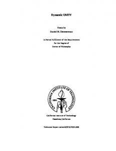
Fig. 1 Scheme of a plate of thickness 2h with a cylindrical defect of diameter D and residual depth e. As an example, a detail of the instantaneous surface displacement associated to an harmonic guided wave that propagates along axis x1 with wavenumber k is shown.
with ij being the stress tensor components and ␦ij the Kronecker delta. In the following we restrict ourselves to harmonic time dependence in such a way that for a single temporal frequency f we have u共r,t兲 = Re关uˆ 共r,t兲兴 = Re关uˆ m共r兲exp共j2 ft兲兴,
14
with scanning optical heterodyne interferometry or shearography.15 Also, a 2-D scalar model has been employed for solving the inverse problem of scattering by cylindrical inclusions in plates using experimental data obtained with a whole-field TV-holography technique close to ours.16 Reported results in Ref. 16 also include the presentation of near- and far-field simulated scattering patterns for different defect types, but a direct comparison between simulated and experimental ultrasonic field values is not presented. In this work we present a novel numerical modeling of ultrasonic Lamb and Rayleigh wave propagation and scattering by through-thickness defects in homogeneous plates, and its verification by comparison with experimental complex amplitude maps of the out-of-plane displacements of the plate surface obtained by a self-developed pulsed TV holography system combined with a two-step spatiotemporal Fourier transform method. We introduce the theoretical framework for modeling in the harmonic regime, and outline the state of the art numerical method employed for obtaining simulated scattering data. The procedure for obtaining experimental data by TV holography, combined with the two-step spatiotemporal Fourier transform method that has been described in detail in previous works 共see Refs. 4, 5, 17, and 18兲, is only briefly outlined here, including essential points for completeness. Comparison between experimental and simulated scattering patterns of narrowband guided waves with holes and slots in aluminum plates shows a fair match, both in near- and far-field zones, which allows a subsequent quantitative characterization of the defects on this basis. To the best of our knowledge, apart from our corresponding recent presentation in a congress,19 this is the first time that such a comparison is reported. 2 Theoretical Framework 2.1 Linear Elasticity Theory The basic relations of linear elasticity theory20 are included here to establish notation and the framework of the simplified scalar model presented later in Sec. 2.3. Referring to the geometry of Fig. 1, 共x1 , x2 , x3兲 denote cartesian coordinates, u = 共u1 , u2 , u3兲 the displacement vector, and Optical Engineering
共3兲
with uˆ being the complex displacement, uˆ m the complex amplitude vector of the wave, and j the imaginary unit. In these conditions, employing Eqs. 共1兲 and 共2兲 in a balance momentum equation for a region free of body forces results in 共L + L兲 ⵜ 共ⵜ · uˆ m兲 + Lⵜ2uˆ m + 2uˆ m = 0,
共4兲
where is the mass density and = 2 f is the circular frequency. Equation 共4兲 is the well-known Lamé-Navier equation for a harmonic regime. Displacement u associated by Eq. 共3兲 to any complex amplitude uˆ m that is the solution of this equation can be discomposed in longitudinal uL and transversal uT components that propagate respectively with phase velocities cL =
cT =
冑
L + 2L ,
共5兲
冑
L .
共6兲
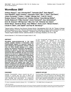
2.2 Guided Waves in Plates and the TwoDimensional Helmholtz Scalar Equation Wave propagation in plates is usually analyzed in terms of particular combinations 共called modes兲 of longitudinal and transversal displacement, characterized by transversal stationary displacement distributions.20 For a given temporal frequency, each mode travels along a direction contained in plane 共x1 , x2兲 with a characteristic phase velocity / k, with k being the corresponding wavenumber of the mode. In the most common case of plates with stress-free boundaries, modes can be classified into two groups: the so-called horizontal shear 共SH兲 modes that have displacement vectors uSH parallel to plane 共x1 , x2兲, and the Lamb modes, with displacement vectors uSV that have in-plane and out-ofplane components 共see Fig. 1兲 and are characterized by the frequency spectrum represented in Fig. 2. SH modes can be described in terms of one scalar potential, but Lamb modes are usually described by using scalar and vector potentials simultaneously 共see Ref. 20兲. Recently, an alternative has been developed by Achenbach
095802-2
September 2010/Vol. 49共9兲
Downloaded from SPIE Digital Library on 25 Oct 2010 to 131.215.220.185. Terms of Use: http://spiedl.org/terms
López-Vázquez et al.: Numerical modeling and measurement by pulsed television holography… 4
S 5 A 5
3 .5
A 3 S 4
3
A 4
2 .5
C
S 2 A 2
S 3 2
S 1
1 .5
A 1 1
S 0
0 .5 0
A 0
1 0
S y m m e tr ic m o d e s A n tis y m m e tr ic m o d e s 2
N
3
4 5
6
Fig. 2 Frequency spectrum of Lamb modes for a plate with stressfree boundaries. ␥ = 2h / cL and = 2hk / are the normalized frequency and wave number, respectively.
that describe Lamb modes with only one scalar potential and two 1-D functions Wn共x3兲 and Vn共x3兲 that characterize transversal shapes for the mode labeled n.21 The out-ofplane component is simply given by un,3 = Wn共x3兲共x1 , x2兲. Hence, as the scalar potential 共x1 , x2兲 verifies the 2-D scalar Helmholtz equation in plane 共x1 , x2兲, it is evident that for each mode n, the equation ⵜ2uˆn,3m + k2nuˆn,3m = 0,
共7兲
is also verified for any plane x3 = constant within the plate. In the following, the symbol ⵜ2 denotes the 2-D Laplacian operator in 共x1 , x2兲, and kn the Lamb wavenumber for mode n. 2.3 Scattering of Guided Waves in Plates by Through-Thickness Defects At this point we restrict the scope of the analysis to scattering phenomena generated by defects with 2-D geometry 共as the case of a through-thickness hole with residual depth e = 0, see Fig. 1兲. In these conditions, plate geometry is 2-D, in the sense that it depends only on 共x1 , x2兲 coordinates. When scattering is produced in conditions in which only one propagating Lamb mode contributes to u3, then Eq. 共7兲 can be employed. Following the approach of Ref. 16, we assume that this is the case. Then, if ⌫ denotes the boundary of the 2-D throughthickness defect and uˆ3m denotes a complex amplitude associated to the out-of-plane component u3共x1 , x2 , h兲 of the scattered field, we can model our problem by means of the partial differential equation,
冦冏
ⵜ2uˆ3m + k2uˆ3m = 0 outside ⌫
uˆ3m n
冏
= g, ⌫
,
冧
共8兲
where g is a function defined on ⌫. Stress-free conditions at defect boundaries imply conditions on the spatial derivatives of the scattered field as a function of the spatial deOptical Engineering
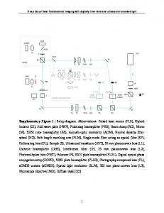
rivatives of the incident field. For this reason, a generic Neumann boundary condition is stated. The validity of this model can be justified a posteriori on the basis of the comparison of model results with experimental data. Nevertheless, and although it is not the objective of this work to justify the model in Eq. 共8兲 and its conditions of applicability from fundamental equations of linear elasticity in Eqs. 共1兲–共4兲, we provide a brief a priori justification of our assumption for the case of throughthickness defects. This can be done by referring to an analytical model based on the Achenbach approach for describing the scattering of Lamb waves by cylindrical holes in plates.22 In particular, it follows from the theoretical discussion presented in this reference that an exact description of the scattering processes under consideration requires adequate account of mode conversion and appearance of SH and Lamb evanescent modes, which result from the stressfree boundary conditions and associated interactions of the incoming waves with the cylinder boundary. Nevertheless, for defects with 2-D geometry, modal conversion occurs only between in-plane components. This means that u3 displacements for Lamb modes are not mixed with contributions of SH modes. Also, a few wavelengths away from the defect, contributions of the evanescent modes are not relevant. Provided the evanescent modes are also small in the neighborhood of the cylinder boundary, the out-of-plane component can be described everywhere as a superposition of incident and scattered Lamb modes. When only one propagating Lamb mode contributes to the out-of-plane component, the Helmholtz equation is completely justified. When several Lamb-mode contributions exist of a given 共fixed兲 frequency, the same can be stated as far as the corresponding Lamb wave numbers are nearly coincident. This is the case of Rayleigh waves that can be understood in the context of guided waves in plates as a superposition of S0 and A0 modes in their overlapping zone of the spectrum 共see Fig. 2兲. 3 Materials and Methods 3.1 Test Plates Experiments were performed in aluminium plates with dimensions 300⫻ 100⫻ 10 mm3 and with through-thickness holes and slots adequately prepared. The longitudinal wave velocity was measured by means of the classical pulse-echo method, resulting in cL = 6358 m / s. Areas without defects were employed for analyzing the incident field. Boundary conditions were studied employing the edge of the plates. In all cases, plates were supported so that the constraints at their surfaces are minimized; they simply rest on a horizontal board covered in velvet fabric. Plasticine was used as an acoustic absorber at the edges of the plates to avoid reflections of the incident and scattered waves that could disturb the measured acoustic fields 共Fig. 3兲. 3.2 Experimental Setup and Procedure for Obtaining the Experimental Complex Amplitude The layout of the experimental system used to generate and detect the elastic waves is depicted in Fig. 4. Rayleigh waves were generated by means of the classical wedge method, in which the longitudinal wave emitted
095802-3
September 2010/Vol. 49共9兲
Downloaded from SPIE Digital Library on 25 Oct 2010 to 131.215.220.185. Terms of Use: http://spiedl.org/terms
López-Vázquez et al.: Numerical modeling and measurement by pulsed television holography…
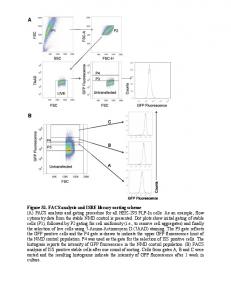
Fig. 3 Reference image for a through-thickness hole 共e = 0兲 of diameter D = 12 mm.
by a piezoelectric transducer is coupled to the plate surface through a Bakelite prismatic coupling block 共wedge兲 of angle w = 65 deg 共Fig. 4兲. A long tone burst consisting of 99 cycles with a central frequency f = 1.000 MHz was used to excite the piezoelectric in a way that the generated Rayleigh wave trains are quasimonochromatic. Under these circumstances, the stress at the plate surface caused by the wedge presents a spatial period and has a phase velocity that correspond, respectively, to wavelength R and phase velocity cR of the Rayleigh wave at frequency f. The wavelength of the produced quasimonochromatic Rayleigh wave R was measured with the procedure described in Ref. 23, resulting in R = 2.96 mm, so that the Rayleigh phase velocity is given by cR = R f, resulting in cR = 2960 m / s. On the other hand, the instantaneous out-of-plane acoustic field u3共r , t兲 at the plate surface due to the propagation of the Rayleigh wave train is measured with a selfdeveloped double-pulsed TV holography system,5 which has been successfully employed to measure quasimonochromatic guided waves in plates with nonspecular finish 共a discussion of the advantages of TV holography compared to other whole-field and pointwise techniques to probe ultrasound can be found in Ref. 4兲. As is common in TV
holography techniques,24 we employ a configuration of an image hologram, sensitive to the out-of-plane component of the displacement of the surface points, with the image sensor of a video camera as a recording medium. There is no optical reconstruction of the recorded holograms, but instead their intensity distribution is electronically processed to render the optical phase-difference map, which depends on the displacements of the specimen surface. The core of the TV holography system is a twin-cavity pulsed, injection-seeded, and frequency-doubled Nd:YAG laser 共Spectron SL404T兲 that emits two laser pulses with a duration of 20 ns and a controlled relative temporal delay. The two pulses are employed for obtaining two correlograms that are recorded successively in separate frames of a charge-coupled device 共CCD兲 camera 关共PCO Kelheim, Germany兲 Sensicam Double-Shutter兴. Each correlogram corresponds to the interference of the reference beam and the object beam scattered back by the plate surface. A processing procedure based on the spatial Fourier transform method is applied to the correlograms,17 which renders the so-called optical phase-change map ⌬⌽共r , t兲, proportional to the instantaneous out-of-plane acoustic displacement field u3共r , t兲, i.e., ⌬⌽共r,t兲 =
8 u3共r,t兲,
共9兲
with = 532 nm being the wavelength of the laser and t the instant of emission of the first laser pulse. The usual scaling factor 共4 / 兲 between the optical phase change and displacement is doubled in Eq. 共9兲 by selecting a delay between laser pulses 共i.e., between the two correlograms兲 equal to an odd number of half-periods of the detected Rayleigh wave. For the case of the experiments presented in this study, we have employed a delay of three half-periods 共that is the minimum number of odd half-periods for which the camera can record the two correlograms in different frames兲. The optical phase-change map given by Eq. 共9兲 represents itself as a useful means to assess the interaction of the Rayleigh wave and defect. However, a second processing procedure based on the Fourier transform can be applied to improve signal-to-noise ratio and calculate the acoustic amplitude u3m共r兲 = mod关uˆ3共r , t兲兴 and the total acoustic phase 3T共r , t兲 = arg关uˆ 3共r , t兲兴 of the Rayleigh wave, from which the complex amplitude uˆ3m共r兲 = u3m共r兲exp关m共r兲兴,
Fig. 4 Experimental setup.
Optical Engineering
共10兲
of the ultrasonic field can be obtained by simply selecting an arbitrary value of time t0, for which m共r兲 = 3T共r , t0兲. Our procedure,18 which consists of an improved version of a previous method described in Ref. 17, is based on the spatiotemporal 3-D Fourier transform of a set of optical phase-change maps corresponding to successive instants delayed by a quarter of the wave period. As long as the ultrasonic waves are narrowband, most of the spectral energy is contained in a small region of the spatial frequency plane and within a thin slice of temporal frequencies, and can be easily filtered and inverse Fourier transformed to obtain the mechanical amplitude and phase of the wave. The selection of the number of maps 关apart from the fact 095802-4
September 2010/Vol. 49共9兲
Downloaded from SPIE Digital Library on 25 Oct 2010 to 131.215.220.185. Terms of Use: http://spiedl.org/terms
López-Vázquez et al.: Numerical modeling and measurement by pulsed television holography…
(a)
(a) -0.044
-0.022
0
0.022
-0.044
0.044
-0.022
0
0.022
0.044
(b)
(b)
(c)
(c)
Fig. 5 Repeatability results. 共a兲 Modulus of reference incident field, 共b兲 difference of the modulus of reference field and another equivalent incident field, and 共c兲 horizontal profiles of 共a兲 共thin兲 and 共b兲 共thick兲. Dimensions are in meters. Midgray level represents zero. Grayscale bars in 共a兲 and 共b兲 and profile amplitude in 共c兲 are in units of / 4. The axis numbering in 共a兲 and 共b兲 corresponds to that of Fig. 3.
Fig. 6 Repeatability results. 共a兲 Real part of reference incident field, 共b兲 difference of the real parts of reference field and another equivalent incident field, and 共c兲 horizontal profiles of 共a兲 共thin兲 and 共b兲 共thick兲. Dimensions are in meters. Midgray level represents zero. Grayscale bars in 共a兲 and 共b兲 and profile amplitude in 共c兲 are in units of / 4. The axis numbering in 共a兲 and 共b兲 corresponds to that of Fig. 3.
that it must be an integer power of 2 to employ fast-Fourier transform 共FFT兲 algorithms兴 stems from a compromise between the attainable improvement of the signal-to-noise ratio of the measured displacements and the data acquisition cost 共time and computational resources兲. In our case, eight optical phase-change maps delayed 250 ns were taken in each experiment, and the spatiotemporal 3-D Fourier transform method was applied to the whole set. The obtained experimental complex amplitude is the raw data for the comparison with numerical simulations. Optical Engineering
3.3 Numerical Method To efficiently produce accurate solutions for Eq. 共8兲, we utilize a modified version of a highly efficient and accurate numerical methodology introduced recently,25 which we describe briefly in what follows. As is well known, the 共unique兲 solution of the Neumann problem in Eq. 共8兲 can be expressed as a double-layer potential
095802-5
September 2010/Vol. 49共9兲
Downloaded from SPIE Digital Library on 25 Oct 2010 to 131.215.220.185. Terms of Use: http://spiedl.org/terms
López-Vázquez et al.: Numerical modeling and measurement by pulsed television holography…
(a)
(a)
(b)
(b)
Fig. 8 Results for the boundary conditions at the edge of the plate. Measured profiles of the real part of the complex amplitude of the total field for several time delays 共thin兲 with the modulus envelope 共thick兲 for incident angle of 共a兲 45 deg and 共b兲 0 deg. Dimensions are in pixels. Profile amplitude in units of / 4. All profiles include zero displacement values for pixels outside the plate area 共see Fig. 7兲, which generates the artifact of a cone that converges to zero, just after the edge, on the right.
uˆ3m共r兲 =
冕
Gk共r,r⬘兲 共r⬘兲dᐉ⬘ . nr⬘ ⌫
共11兲
Here Gk denotes the Hankel function (c)
i Gk共r,r⬘兲 = H10共k兩r − r⬘兩兲, 4
共12兲
and, letting N denote the hypersingular operator, N共兲共r兲 = lim
z→⬁
nr
冕
⌫
Gk共r,r⬘ + znr⬘兲 nr⬘
共r⬘兲dᐉ⬘ ,
共13兲
the density is the unique solution of the first kind integral equation N共兲 = g. (d)
Fig. 7 Results for the boundary conditions at the edge of the plate for an incident angle of 45 deg. 共a兲 Reference image 共in white light兲 of the plate and the edge, which is the horizontal transition at pixel 500, and 共b兲, 共c兲, and 共d兲 are modulus, real part, and phase of the complex amplitude of the total field, respectively. Dimensions are in pixels. Midgray level represents zero. Grayscale bars in 共b兲 and 共c兲 are in units of / 4. The axis numbering of 共a兲, 共b兲, 共c兲, and 共d兲 corresponds to that of Fig. 3. Note that in 共b兲, 共c兲, and 共d兲 the values are zero for pixels located outside the plate area below the edge transition.
Optical Engineering
共14兲
Once the unknown surface density has been obtained, the solution uˆ3m of Eq. 共8兲 can be produced at any point outside ⌫ by applying numerical quadrature to Eq. 共11兲. Our numerical solver produces approximate solutions of Eq. 共14兲 for a given right-hand side g by seeking a set of values j ⬇ 共r j兲 of the unknown at a set of points r j 共j = 1 , . . . , n兲 on the curve ⌫. The algorithm relies on a highly accurate approximation of the integral in Eq. 共14兲, which can be obtained by appealing to an expression of the right-hand side of Eq. 共13兲 that only uses tangential derivatives, in conjunction with interpolation of the values j by
095802-6
September 2010/Vol. 49共9兲
Downloaded from SPIE Digital Library on 25 Oct 2010 to 131.215.220.185. Terms of Use: http://spiedl.org/terms
López-Vázquez et al.: Numerical modeling and measurement by pulsed television holography…
trigonometric polynomials, and exact differentiation and integration of trigonometric monomials. To resolve high curvatures while taking advantage of the excellent properties of trigonometric interpolation, the method utilizes smooth changes of variables that map an equispaced grid in the interval 关0 , 2兴 to a grid on ⌫ that contains a high density of discretization points r j in high curvature portions of ⌫. Note, in particular, that as a result of this discretization strategy, the density of discretization points r j varies smoothly along ⌫. The method then proceeds by constructing a linear system of equations for the quantities j, which arises as the discretized version of the left-hand-side in Eq. 共14兲 is set to equal the right-hand side of that equation at each point r j, j = 1 , . . . , n. The algorithm is then completed by solving this linear system by means of a numerical implementation of the Gaussian elimination method. It was verified through a variety of numerical experiments, including comparisons with exact solutions, that the solutions uˆ3m produced by this methodology are highly accurate, and that the associated errors decay rapidly as discretizations are refined. 4 Results and Discussion 4.1 Incident Field Characterization To know the characteristics of the incident acoustic field and the repeatability of the measured maps, a series of acquisitions in the same conditions was performed at time intervals of 5 min. After processing the raw images in the same manner with identical parameters, the modulus 关Fig. 5共a兲兴 and the real part 关Fig. 6共a兲兴 of the acoustic field were obtained. The deviations between maps 关Figs. 5共b兲 and 6共b兲兴 were of the order of 20% for both amplitude 关Fig. 5共c兲兴 and real part 关Fig. 6共c兲兴. Taking into account that the typical value of the amplitude was about 5 nm, these values are in accordance with a previous estimation of the noise of the technique.4 Other features of interest are the slight curvature of the wavefronts, clearly noticeable in Fig. 6共a兲, and a nonuniform amplitude profile in a section transverse to the main propagation direction 关visible as the gray-level variation along any vertical line in Fig. 5共a兲兴. Both features complicate the comparison between experimental and numerical results. 4.2 Boundary Conditions To gain understanding about the boundary conditions to apply at the border of the defects, we studied the reflection of the incident acoustic field at the straight edge of a plate without defects for different incidence angles. The obtained results 共Figs. 7 and 8兲 approximately correspond to the superposition of two plane traveling waves of similar 共but not equal兲 amplitudes, with the reflection angle equal to the incidence one. Although the observed boundary conditions are neither Dirichlet nor Neumann, they are not far from the Neumann ones 关i.e., g = 0 in Eq. 共8兲兴. So, we adopted them as a starting point for the numerical simulations of the scattering patterns. 4.3 Scattering Patterns In Figs. 9 and 10, the comparison between the experimental and simulated scattering patterns of Rayleigh waves corresponding to a hole and a slot are presented. A simple visual Optical Engineering
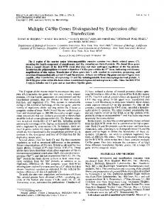
Fig. 9 Scattering patterns for a cylindrical hole with D = 12 mm. Comparison of complex amplitudes: 共a兲 and 共c兲 are experimental, 共b兲 and 共d兲 are numerical; 共a兲 and 共b兲 are the modulus, and 共c兲 and 共d兲 phase. Dimensions are in meters. Midgray level represents zero. Grayscale bars in 共a兲 and 共b兲 are in units of / 4. The axis numbering corresponds to that of Fig. 3.
095802-7
September 2010/Vol. 49共9兲
Downloaded from SPIE Digital Library on 25 Oct 2010 to 131.215.220.185. Terms of Use: http://spiedl.org/terms
López-Vázquez et al.: Numerical modeling and measurement by pulsed television holography…
(a)
(a)
(b)
Fig. 11 Profiles along the white horizontal line marked in Fig. 3 correspond to maps of Fig. 9: 共a兲 modulus of complex amplitude of the total field, 共b兲 modulus of complex amplitude of scattered field, 共thick兲 experimental, and 共thin兲 numerical. Profile amplitude is in units of / 4.
(b)
Fig. 10 Scattering patterns for a slot of mean width of 4.4 mm and length of 24 mm. Modulus of complex amplitude: 共a兲 experimental and 共b兲 numerical. Dimensions are in meters. Midgray level represents zero. Grayscale bars in 共a兲 and 共b兲 are in units of / 4. The axis numbering corresponds to that of Fig. 3.
inspection reveals their close agreement both in modulus and phase. Small differences between Figs. 10共a兲 and 10共b兲 can be observed that are most noticeable in the shadow region and could be associated, among other reasons, to the neglect in our 2-D approximation of the near-field evanescent modes. For quantitative comparison, the profiles along a central line of the maps, both for the total and scattered fields, are presented 共Fig. 11兲. Even though the main features of the scattering pattern appear well correlated, the pixel-to-pixel agreement between maps is not as good as their 2-D visual matching. This is in consonance with measured noise levels. At this point, image processing techniques that average or reject noise on the basis of spatial or morphological filtering could be applied. A more comprehensive analysis of these issues will be addressed in future work, but in any case, we believe that the presented results are enough to say that the experimental contrast of the numerical simulation is positive.
5 Conclusions Scattering of elastic waves in plates is studied, employing 2-D maps of instantaneous out-of-plane displacements Optical Engineering
obtained with a self-developed pulsed TV holography system. Experimental data are compared with simulated scattering patterns employing a state of the art numerical technique. The achieved agreement gives support to the employed 2-D model. To improve the reliability of this model, further work should be done to analyze more defect typologies and sizes under different Lamb modes and frequencies. Acknowledgments This work was cofunded by the Spanish Ministerio de Ciencia e Innovación and by the European Comission 共ERDF兲 in the context of the Plan Nacional de I + D + i 共project number DPI2008-02709兲, and by the Dirección Xeral de Investigación, Desenvolvemento e Innovación da Xunta de Galicia in the context of the Plan Galego de IDIT 共project number INCITE08PXIB303252PR兲. Supplementary cofunding from the Universidade de Vigo 共project number I608122F64102兲 is also acknowledged. Amlani and Bruno gratefully acknowledge support by the Air Force Office of Scientific Research and the National Science Foundation. References 1. Nondestructive Testing Handbook, 2nd ed., vol. 7, A. S. Birks, R. E. Green Jr., and P. McIntire, Eds., pp. 1–215, Ultrasonic Testing, American Society for Nondestructive Testing, Columbus, OH 共1991兲. 2. L. J. Bond, “Numerical techniques and their use to study wave propagation and scattering—a review,” in Elastic Waves and Ultrasonic Nondestructive Evaluation, Y. S. Rajapakse, S. K. Datta, and J. D. Achenbach, Eds., pp. 17–27, Elsevier Science Publisher 共1990兲. 3. C. B. Scruby and L. E. Drain, Laser Ultrasonics. Techniques and Applications, Adam Hilger, Bristol, United Kingdom 共1990兲.
095802-8
September 2010/Vol. 49共9兲
Downloaded from SPIE Digital Library on 25 Oct 2010 to 131.215.220.185. Terms of Use: http://spiedl.org/terms
López-Vázquez et al.: Numerical modeling and measurement by pulsed television holography… 4. J. L. Fernández, A. F. Doval, C. Trillo, J. L. Deán, and J. C. López, “Video ultrasonics by pulsed TV holography: a new capability for non-destructive testing of shell structures,” Intl. J. Optomechatron. 1, 122–153 共2007兲. 5. C. Trillo, D. Cernadas, A. F. Doval, C. López, B. V. Dorrío, and J. L. Fernández, “Detection of transient surface acoustic waves of nanometric amplitude with double-pulsed TV holography,” Appl. Opt. 42, 1228–1235 共2003兲. 6. Y. Cho and J. L. Rose, “A boundary element solution for a mode conversion study on the edge reflection of lamb waves,” J. Acoust. Soc. Am. 99, 2097–2109 共1996兲. 7. B. Morvan, N. Wilkie-Cahncellier, H. Duflo, A. Tinel, and J. Duclos, “Lamb wave reflection at the free edge of a plate,” J. Acoust. Soc. Am. 113, 1417–1425 共2003兲. 8. M. Castaings, E. Le Clezio, and B. Hosten, “Modal decomposition method for modeling the interaction of lamb waves with cracks,” J. Acoust. Soc. Am. 112, 2567–2582 共2002兲. 9. B. Masserey and E. Mazza, “Analysis of the near-field ultrasonic scattering at a surface crack,” J. Acoust. Soc. Am. 118, 3585–3594 共2005兲. 10. G. R. Liu, “A combined finite element/strip method for analysing elastic wave scattering by cracks and inclusion in laminates,” Comput. Mech. 28, 76–81 共2002兲. 11. S. Banerjee and T. Kundu, “Scattering of ultrasonic waves by internal anomalies in plates,” Opt. Eng. 46, 053601-1 to -9 共2007兲. 12. C. Vemula and A. N. Norris, “Flexural wave propagation and scattering of on thin plates using Mindlin theory,” Wave Motion 26, 1–12 共1997兲. 13. C. H. Wang and F. K. Chang, “Scattering of plate waves by a cylindrical inhomogeneity,” J. Sound Vib. 282, 429–451 共2005兲. 14. P. Fromme and M. B. Sayir, “Measurement of the scattering of a Lamb wave by a through hole in a plate,” J. Acoust. Soc. Am. 111, 1165–1170 共2002兲. 15. F. Taillade, “Association de la shearographie et des ondes de Lamb pour la détection rapide et quantitative des délaminages,” PhD Thesis, Conservatoire National des Arts et Métiers 共2000兲. 16. T. D. Mast and G. A. Gordon, “Quantitative flaw reconstruction from ultrasonic surface wavefields measured by electronic speckle pattern interferometry,” IEEE Trans. Ultrason. Ferroelectr. Freq. Control 48, 432–444 共2001兲. 17. C. Trillo, A. F. Doval, D. Cernadas, O. López, J. C. López, B. V. Dorrío, J. L. Fernández, and M. Pérez-Amor, “Measurement of the complex amplitude of transient surface acoustic waves using doublepulsed TV holography and a two-stage spatial Fourier transform method,” Meas. Sci. Technol. 14, 2127–2134 共2003兲. 18. C. Trillo and A. F. Doval, “Spatiotemporal Fourier transform method for the measurement of narrowband ultrasonic surface acoustic waves with TV holography,” Proc. SPIE 6341, 63410M 共2006兲. 19. J. C. López-Vázquez, J. L. Deán, C. Trillo, A. F. Doval, J. L. Fernández, F. Amlani, and O. P. Bruno, “Modeling for characterizing defects in plates using two-dimensional maps of instantaneous ultrasonic outof-plane displacement obtained by pulsed TV-holography,” Proc. SPIE 7389, 738937 共2009兲. 20. J. L. Rose, Ultrasonic Waves in Solid Media, pp. 200–240, Cambridge University Press, Cambridge, UK 共2000兲. 21. J. D. Achenbach, Reciprocity in Elastodynamics, pp. 116–131, Cambridge University Press, Cambridge, UK 共2003兲. 22. O. Diligent, T. Grahn, A. Bostrom, P. Cawley, and M. J. S. Lowe, “The low-frequency reflection and scattering of the S0 Lamb mode from a circular through-thickness hole in a plate: Finite Element, analytical and experimental studies,” J. Acoust. Soc. Am. 112, 2589– 2601 共2002兲. 23. J. L. Deán, C. Trillo, A. F. Doval, and J. L. Fernández, “Determination of thickness and elastic constants of aluminum plates from fullfield wavelength measurements of single-mode narrowband Lamb waves,” J. Acoust. Soc. Am. 124, 1477–1489 共2008兲. 24. A. F. Doval, “A systematic approach to TV-holography,” Meas. Sci. Technol. 11, R1–R36 共2000兲. 25. O. P. Bruno and S. K. Lintner, “Generalized Calderon formula and second-kind integral solvers for TE and TM problems of diffraction by open arcs” 共unpublished兲.
X. Luís Deán-Ben received the diploma in automatics and electronics engineering from the Universidade de Vigo in 2004. He received the PhD degree also from the Universidade de Vigo in 2009, after completing his PhD thesis in the nondestructive testing of plates with TV holography measurements of Lamb waves.
Cristina Trillo received her automatics and electronics engineer and PhD degrees from the University of Vigo in 1999 and 2004, respectively. She joined the Department of Applied Physics of the University of Vigo in 2000 as a research associate. Her main research interests within the optical metrology group are image processing, optical measurement, and nondestructive inspection by TV holography.
Ángel F. Doval received his automatics and electronics engineer and PhD degrees from the Universities of Santiago de Compostela in 1990 and Vigo in 1997, respectively. He joined the Department of Applied Physics of the University of Vigo in 1990 as a lecturer; since 1998 he has held a senior lectureship. His research with the optical metrology group focuses on optical measurement and nondestructive inspection by digital holography, TV holography, and other interferometric techniques.
José L. Fernández received his diploma in mechanical engineering from Universidad Politécnica de Madrid in 1984, and his PhD degree in engineering in 1988 from Universidad de Santiago de Compostela. He is currently a full professor of applied physics and head of the optical metrology group in the University of Vigo. His research interest includes dimensional measurements and nondestructive inspection by optical techniques, in particular TV holography, interferometry, and moiré techniques.
J. Carlos López-Vázquez received his MPhil degree in physics from the University of Santiago de Compostela in 1988, and his PhD degree in applied physics from the University of Vigo in 1997, where is currently an associate professor. His research interests are related to optical techniques for nondestructive testing applications in industry and modeling and simulation of wave propagation phenomena.
Optical Engineering
095802-9
Faisal Amlani is a PhD student in the Department of Applied and Computational Mathematics at the California Institute of Technology 共Caltech兲 in Pasadena, California.
September 2010/Vol. 49共9兲
Downloaded from SPIE Digital Library on 25 Oct 2010 to 131.215.220.185. Terms of Use: http://spiedl.org/terms
López-Vázquez et al.: Numerical modeling and measurement by pulsed television holography… Oscar P. Bruno received his PhD degree from the Courant Institute of Mathematical Sciences, New York University. Following graduation, he held a position for two years as a visiting assistant professor with the University of Minnesota, and then joined the faculty of the Georgia Institute of Technology 共Georgia Tech兲, where he held positions as an assistant professor and associate professor. After a four-year period with Georgia Tech, he joined the faculty of the California Institute of Technology 共Caltech兲, Pasadena, where he is
Optical Engineering
now a professor in the Department of Applied and Computational Mathematics, having served as executive officer during 1998 to 2000. His research interests lie in areas of optics, elasticity and electromagnetism, remote sensing and radar, overall electromagnetic and elastic behavior of materials 共solid, fluids, composites materials, and multiple-scale geometries兲, and phase transitions. He is a recipient of a Friedrichs Award for an outstanding dissertation in mathematics from the Courant Institute, a Young Investigator Award from the National Science Foundation, and a Sloan Foundation Fellowship.
095802-10
September 2010/Vol. 49共9兲
Downloaded from SPIE Digital Library on 25 Oct 2010 to 131.215.220.185. Terms of Use: http://spiedl.org/terms