AbstractâVideo surveillance is currently one of the most active area of research in both academia and industry. Though much work has been done in the area of ...
Object-based Surveillance Video Compression using Foreground Motion Compensation R. Venkatesh Babu and Anamitra Makur School of Electrical and Electronics Engineering Nanyang Technological University, Singapore Abstract— Video surveillance is currently one of the most active area of research in both academia and industry. Though much work has been done in the area of smart surveillance, relatively little work has been reported to compress the surveillance videos. In this paper, we propose an object based video compression system using foreground motion compensation for applications such as archival and transmission of surveillance video. The proposed system segments independently moving objects from the video and codes them with respect to the previously reconstructed frame. The error resulting from object-based motion compensation is coded using SA-DCT procedure. The proposed system codes the surveillance video using far lesser bits compared to conventional video compression techniques.
Camera Background Modeling Moving Object Detection
Object Tracking
Keywords—Surveillance, Video Compression, Video Object Segmentation
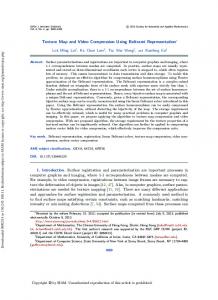
I. I NTRODUCTION Surveillance systems are meant to monitor, screen and track activities in public places such as airports, in order to ensure security. Many varied aspects like screening objects and people, maintaining the database of potential threats, biometric identification and video surveillance, act in tandem to monitor activity. The spectrum of surveillance applications include access control in special areas, human identification, event detection/recognition, traffic monitoring, patient monitoring at hospitals and activity monitoring at public places like shopping malls, industries, banks and government establishments. Several surveillance systems have been proposed for varied applications. A typical surveillance system consists of multiple visual information processing modules. For example, single camera surveillance system contains the following major stages as shown in Fig. 1 : background modeling, motion detection, object tracking, event detection/recognition. Each of the modules themselves form active research areas. A major aspect of any surveillance system is to efficiently compress the huge volumes of recorded video, to facilitate subsequent processing. However, this aspect has not been sufficiently explored as compared to the other modules in the system, among the reported works. The importance of video compression for any surveillance system is manifold. Efficient archival of surveillance video is an important task of a smart surveillance system. These archived videos are useful for post analysis of events and behavior understanding. Most of the surveillance videos, especially in sensitive places like airports and banks, are recorded continuously 24 hours a day and stored
c 2006 IEEE 1–4244–0342–1/06/$20.00 �
Event Detection/ Recognition Fig. 1.
A general framework of visual surveillance system
for a period ranging from few weeks to many months. In such situations, it is essential to have efficient compression that can bring down storage space requirements drastically. Apart from archival of surveillance video, compression plays a crucial role in networked surveillance systems. For example, nowadays, security cameras are used in public transport systems for passenger safety; along highways to monitor traffic jams and important public gatherings are monitored as security measures. These systems are network-connected for centralized real-time monitoring. Bandwidth is a major issue for such network-connected monitoring system. Here, compression technology plays a crucial role in efficiently utilizing the available bandwidth for real-time monitoring via various network protocols such as TCP/IP. These large-scale surveillance video recordings critically need efficient compression techniques to store the video for long-term archival in order to support threat detection. Such massive data archiving and processing call for efficient compression techniques. Though there have been many video technologies and compression standards, it is hard to find a dedicated system for archival of surveillance video. There have been few reported works based on MPEG-4 object-based encoding for surveillance video [1], [2]. Nishi et al., [3] have proposed object-based coding using pixel state analysis. This results in bit-saving only for a certain class of video sequences, while for some sequences the performance is less than MPEG
ICARCV 2006
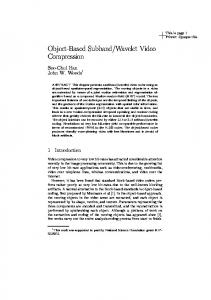
coding due to overhead in coding the pixel state information. Archiving the surveillance video is currently a major topic of research. The magnitude of video data involved makes efficient compression technology very critical. In this paper we address the issue of compressing surveillance video. The approach we have explored here is object based video compression. Here, the moving objects were segmented from the background using an edge-based technique. The current frame objects are motion compensated with respect to the previously reconstructed frame and the resulting error is coded using a object-based shape adaptive discrete cosine transform (SADCT) technique. The objective of any smart surveillance system is higher level vision analysis and interpretation of the situation, usually referred to as event detection or behavior understanding. This involves analysis and recognition of motion patterns, and interpretation of high-level description of actions and interactions [4], [5], [6]. These recognition algorithms use the low-level vision modules for interpreting the situation. The proposed compression approach actually achieves the major low-level vision processes such as object detection, segmentation and object motion, the preliminary tasks towards higher-level understanding. The paper is organized as follows: Section 2 explains the proposed video compression technique that includes modules of object segmentation, motion estimation/compensation, shape coding and object error coding. The experimental results and discussion are detailed in section 3. Section 4 concludes the paper. II. P ROPOSED SURVEILLANCE VIDEO C OMPRESSION T ECHNIQUE Most surveillance systems have fixed cameras, and hence it is justified to assume that the background seen by the surveillance camera is known a’priori. In the case of not knowing the background, it can be very well constructed using the appropriate background generation algorithms [7], [8], [9]. Hence we assume that the background image is available a’priori. In this work, we first segment the foreground objects from the background. Next, the foreground object motion between the current and previous frames is obtained. Finally, the motion compensated error and the object parameters (object boundary, location and motion information) are coded using suitable source coding tools for video compression. The overview of the proposed algorithm is illustrated in Fig. 2. A. Object Segmentation Object segmentation is one of the main issues in objectbased video compression. Better segmentation accuracy reduces the amount of bits required to code the video. In this work, the following image attributes are used for separating the foreground object from the background: i) Object pixels ii) Object edge map and iii) Object difference edge map. Object pixels O are obtained by subtracting the current frame from the background image.
F(n) F(n+1)
Background
Object
Motion Parameter
Segmentation
Extraction
Encode : Error image, Object location, Motion, boundary
Fig. 2.
The overview of the proposed compression technique
� O(i, j)
Encoded Video
=
1 : 0 :
if |fn (i, j) − fbg (i, j)| > τo (1) otherwise
where, fn and fbg represent the current and background images respectively. Since the background luminance changes with time, a small threshold τo , set at 6% of maximum illumination is used for segmenting object pixels in our experiments. Object edgemap (Eo ) is obtained as the difference of edge maps of current frame and background. Eo = |Φ(fn ) − Φ(fbg )|
(2)
where the edge maps Φ(f ) are obtained by the Canny edge detector. Difference edgemap (Ed ) is also obtained in a similar fashion, as given below. Ed = |Φ(fn ) − Φ(fn−1 )|
(3)
Figure 3 shows examples of the aforementioned image attributes. 1) Algorithm: The segmentation algorithm uses morphological operations to extract the foreground objects. 1) The object pixels obtained by background subtraction are noisy and hence not suitable for binary morphological operations. In order to make the operation robust, we obtain the foreground binary image as, the aggregation of object pixels with all ‘on’ pixels of object edge map (Eo ) and difference edge map (Ed ) (see Fig. 4 (a)). 2) Perform ‘flood fill’ operation to fill the holes inside the object. 3) Perform binary opening followed by close operation to remove the noisy pixels. 4) The binary opening/closing operations performered in the previous step results in noisy objects due to the presence of noisy object edges as shown in Fig. 4 (b). These noisy objects are removed on the basis of size and pixel density. • First the objects that occupy number of pixels less than a certain threshold are removed. In our system we set this minimum threshold at 100 pixels.
Fig. 3.
•
(a)
(b)
(c)
(d)
(a) Original image (b) The object pixels (O) (c) object edge map (Eo ) and (d) difference edge map (Ed )
For the remaining objects, the pixel density ρ is computed as follows, No. of ‘on’ object pixels in k-th object (4) ρk = Area of the k-th object
The objects, whose ρ value is less than a threshold (Tρ ) is removed. In our system the value of (Tρ ) is set at 0.5, which demands that at least 50% of the object pixels do not belong to background. Fig. 4 illustrates the segmentation algorithm steps 1,3 and 4.
Motion estimation plays a critical role in video compression. Accurate motion estimation drastically reduces the bits required to encode the error. In our system, motion estimation is done for each object individually. Here, we use sum-ofsquared differences (SSD) based motion estimation for objects. Let f˜n−1 be the recently reconstructed frame.
u∈W
�
Mj [f˜n−1 (u + xj ) − fn (xj )]2
j
(5)
where j indicates the object number, ussd is the motion vector, j Mj is the binary object mask obtained from the segmentation phase, xj is the location of the object in nth frame, fn−1 and fn are the two consecutive intensity images, W is the search window around xj . The obtained motion vector is used for reconstructing the current frame object from the previously reconstructed frame.
(6)
j
where fˆn is the reconstructed frame by object-based motion ¯ j denotes binary complement of the object compensation, M mask Mj , Bg is the background frame and Π represents the multiplication operation. The resulting error after motion compensation of each object needs to be coded. The motion compensated object error (∆j ) is given as follows. ∆j = Mj (fn − fˆn )
B. Foreground Motion Estimation and Compensation
ussd = arg min j
The motion compensation is performed as follows. � ¯j + Mj [f˜n−1 (ussd + xj )] fˆn = BgΠj M
(7)
Object error coding is discussed in the following subsection. C. Object Error Coding Error obtained after motion compensation (∆) is coded using object based SA-DCT procedure [10]. In our procedure the SA-DCT is applied separately to each object as a whole, rather than to blocks of 8 × 8. The procedure for object based SA-DCT is as follows: 1) Shift each column upwards and align them along the top-most row (see Fig. 5 (b)). 2) Perform n point DCT along each column, where n is the number of elements in the corresponding column. For example, in Fig. 5 (b), 2 point DCT is taken for column 3 while 4 point DCT is carried out for column 5. 3) Shift each row left and align them along the left-most column (see Fig. 5 (c)).
(a)
(b) Segmentation algorithm: (a) step 1 (b) step 3 and (c) step 4
4) Perform n point DCT along each row, where n is the number of elements in the corresponding row. For example, 9 and 7 point DCT is carried out for rows 1 and 2 respectively in Fig. 5 (c). 5) Quantize the DCT coefficients for a given quantization factor Q. ˆj Figure 5 illustrates the object based SA-DCT steps. Let ∆ be the reconstructed motion compensation object error, then the reconstructed image f˜n is given by: � ˆj f˜n = fˆn + Mj ∆ (8) j
D. Object Shape Coding The Freeman chain code [11] is a compact way to represent the contour of an object. The chain code is an ordered sequence of n links {ci , i = 1, 2, . . . n}, where ci is a vector connecting neighboring contour pixels. The directions of ci are coded with integer values k = 0, 1, ..., 7 in a counterclockwise sense starting from the direction of the positive x-axis. Further, to increase the coding efficiency, the chain code is differentially coded. Let C be the chaincode, then the corresponding differential chain code is obtained as, � Ci if i = 1 (9) Di = otherwise Ci − Ci−1 E. Algorithm Summary The proposed algorithm is summarized below. 1) Extract the foreground objects using the background image and the object edges as described in subsection II-A. 2) Perform object-based motion compensation for the current frame using the previously reconstructed frame and estimated motion vector. 3) Obtain object-based SA-DCT coefficients for the motion compensation error of each object for a given quantization factor. 4) Encode each object’s boundary, motion vector, location in image plane and motion compensated error using arithmetic coding.
5500 Q 16 Q 32
5000 4500 4000
Bits
Fig. 4.
(c)
3500 3000 2500 2000 1500 1000
0
5
10
15
20
25
30
35
Frames
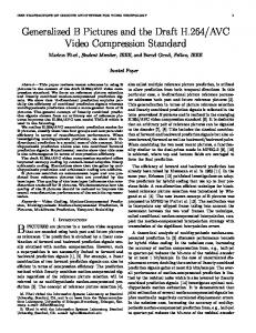
Fig. 6. Bits required for encoding each frame of ’walk’ sequence for quantization value of 16 (blue line) and 32 (red line).
III. E XPERIMENTAL R ESULTS To test the algorithm, we have used video sequences obtained from CAVIAR (Context Aware Vision using Imagebased Active Recognition) project site [12]. Reconstructed images using the proposed technique for quantization values (Q) of 16 and 32 for ’walk’ sequence are given in Fig. 11 which is a typical surveillance sequence. The corresponding bit-rates for encoding the video for the above mentioned quantization are given in Fig. 6 and the corresponding MSE for Y component is given in Fig. 7. It can be observed from these figures, that the average bit-rate (bits/frame) falls from 4271 to 3004 when the quantization factor is increased from 16 to 32. On the other-hand the corresponding reconstruction error (in MSE) increases but marginally from the average value of 14.42 to 14.97. This property allows us to go for higher compression with marginal degradation of image quality. To show the efficacy of our proposed compression technique, we have compared the results with the existing MPEG-1 standard. Figure 8 shows the reconstruction error (MSE) plot for both the methods applied to ’walk’ sequence. For a better reconstruction error compared to MPEG (proposed method MSE=14.97 for quantization factor 32 and MSE=38.2 for MPEG reconstruction), the average bit-rate for the proposed technique is 3004 bits/frame and for MPEG coding it is 79551 bits/frame. Table I shows the performance of the proposed method as compared against MPEG-1 compression for test video sequences. The bit-rate greatly depends upon the size
(a) Fig. 5.
(b)
(c)
Object based SA-DCT : (a) Object to be coded (b) Shift up (c) Shift left
22
60 Proposed(CbCr) Proposed (Y) MPEG (Y) MPEG (CbCr)
20
50
18
40
MSE
MSE
Q 16 Q 32
16
30
14
20
12
10
10
0
5
10
15
20
25
30
0
35
0
5
10
15
Frames
of the foreground object. For example, though frame size of ’walk’ and ’crowd’ are same, the number of bits required for encoding each sequence vastly vary. In ’walk’ sequence the foreground contains only 2 persons where as in ’crowd’ sequence there are 4 persons walking. In ’hall-monitor’, though 1 or 2 persons are seen walking, the bit-rate increases due to the size of the foreground objects. Bit-rate, in a sense, represents the amount of activity in the video sequence. On the contrary, it can be observed from Table I, that the bitrate of MPEG coding almost remains constant irrespective of foreground activity, since it is coded for a specific bit-rate (in our simulations the MPEG sequence is coded at 2 Mbit/s). Comparison of reconstruction error for the ’crowd’ and ’hall monitor’ sequences is shown in Figs. 9 and 10. IV. C ONCLUSION In this paper we have presented an object-based compression technique for surveillance videos. Very high compression rate is achieved by coding the moving objects with motion compensation. The performance of the proposed compression technique is compared with that of the standard MPEG-1 compression technique. Since the object segmentation algorithm is based on the edge information alone, and the motion compensation is done only for the object region, the proposed algorithm is suitable for real-time video coding. V. ACKNOWLEDGEMENT This work is supported under I2 R-NTU joint R&D (2) project.
25
30
35
Fig. 8. Comparison of error for each encoded frame of ’walk’ sequence using proposed method (quantization value 32) with MPEG encoding.
60 Proposed(Y) Proposed (CbCr) MPEG (Y) MPEG (CbCr)
50
40
MSE
Fig. 7. Error in MSE for each encoded frame of ’walk’ sequence for quantization value of 16 (blue line) and 32 (red line).
20
Frames
30
20
10
0
0
10
20
30
40
50
60
Frame
Fig. 9. Comparison of error for each encoded frame of ’crowd’ sequence using proposed method (quantization value 32) with MPEG encoding.
R EFERENCES [1] A. Vetro, T. Haga, K. Sumi, and H. Sun, “Object-based coding for long-term archive of surveillance video,” in IEEE International Conf. on Multimedia and Expo, July 2003. [2] C. Kim and J-N. Hwang, “Object-based video abstraction for video surveillance system,” IEEE Trans. Circuits and Systems for Video Technology, vol. 12, no. 12, pp. 11281138, Dec. 2002. [3] T. Nishi and H. Fujiyoshi, “Object-based video coding using pixel state analysis,” in IEEE Intl. Conference on Pattern Recognition, 2004. [4] R. Venkatesh Babu and K. R. Ramakrishnan, “Recognition of human actions using motion history information extracted from the compressed video,” Image and Vision Computing, vol. 22, no. 8, pp. 597–607, Aug. 2004. [5] N. Johnson and D. Hogg, “Learning the distribution of object trajectories for event recognition,” Image and Vision Computing, vol. 14, no. 8, pp. 609615, 1996. [6] T.Wada and T. Matsuyama, “Multi-object behavior recognition by event
TABLE I C OMPARISON OF PROPOSED METHOD (Q=32) WITH MPEG-1
Sequence Walk Crowd Hall-monitor
Proposed Q=16 Bytes/fr MSE 534 14.42 1152 22.8 1386 23.36
Proposed Q=32 Bytes/fr MSE 376 14.97 741 24.7 832 25.7
MPEG-1 Bytes/fr MSE 9944 38.2 9998 30.6 10000 54.3
(a)
(b)
(c) Fig. 11.
(a) Original images corresponding to frame numbers 5,15 and 25. (b) reconstructed frames with Q=16 (c) and with Q=32.
[7]
90 Proposed(Y) Proposed (CbCr) MPEG (Y) MPEG (CbCr)
80 70
[8]
MSE
60 50
[9]
40 30
[10]
20 10 0
0
10
20
30
40
50
60
[11]
Frame
[12] Fig. 10. Comparison of error for each encoded frame of ’hall monitor’ sequence using proposed method (quantization value 32) with MPEG encoding.
driven selective attention method,” IEEE Trans. Pattern Anal. Machine Intelligence, vol. 22, pp. 873887, Aug. 2000. A. Elgammal, R. Duraiswami, D. Harwood, and Larry S. Davis, “Background and foreground modeling using nonparametric kernel density estimation for visual surveillance,” Proceedings of the IEEE, vol. 90, no. 7, pp. 11511163, July 2002. C. Stauffer and W. E. L. Grimson, “Adaptive background mixture models for real-time tracking,” in IEEE International Conference on Computer Vision and Pattern Recognition, 1999, pp. 246–252. K. Toyama, J. Krumm, B. Brumitt, and B. Meyers, “Wallflower: Principles and practice of background maintenance,” in International Conference on Computer Vision, 1999, pp. 255–261. T. Sikora and B. Makai, “Shape adaptive dct for generic coding of video,” IEEE Trans. Circuits and Systems for Video Technology, vol. 5, no. 1, pp. 59–62, Feb. 1995. H. Freeman, “On the encoding of arbitrary geometric configurations,” IRE Trans. Electronic Computers, vol. EC-10, pp. 260–268, June 1961. “Caviar: Context aware vision using image-based active recognition,” http://homepages.inf.ed.ac.uk/rbf/CAVIAR/.