On the Position Accuracy of Mobile Robot Localization based on Particle Filters Combined with Scan Matching. Jörg Röwekämper. Christoph Sprunk.
On the Position Accuracy of Mobile Robot Localization based on Particle Filters Combined with Scan Matching J¨org R¨owek¨amper Cyrill Stachniss
Christoph Sprunk Patrick Pfaff
Abstract— Many applications in mobile robotics and especially industrial applications require that the robot has a precise estimate about its pose. In this paper, we analyze the accuracy of an integrated laser-based robot pose estimation and positioning system for mobile platforms. For our analysis, we used a highly accurate motion capture system to precisely determine the error in the robot’s pose. We are able to show that by combining standard components such as Monte-Carlo localization, KLD sampling, and scan matching, an accuracy of a few millimeters at taught-in reference locations can be achieved. We believe that this is an important analysis for developers of robotic applications in which pose accuracy matters.
I. I NTRODUCTION Localization is a well studied problem in mobile robotics since the information about the robot’s pose is essential for many applications. Over the last 20 years, several probabilistic localization techniques have been proposed and they have demonstrated the capability to robustly estimate the pose of robots in a large variety of application scenarios. Especially in industrial applications, a key requirement is the high localization and positioning accuracy of the robot on the factory floor. Precise positioning typically is a prerequisite to perform docking or mobile manipulation tasks such as pick and place. A typical example from factory floors is that of a mobile manipulation robot that has to pick up objects from predefined locations such as work benches. As most industrial robots, due to safety restrictions, are equipped with expensive laser rangefinders, they typically do not rely on additional sensors. Before grasping the objects, the robot is required to position itself precisely in front of the corresponding work bench in such a setup. Popular solutions to accurately position a robot with respect to predefined reference locations or to follow predefined trajectories in industrial systems rely on modifications of the environment such as wires embedded in the floor or magnetic tapes on the floor. Environment modifications, however, limit the flexibility of a robotic system. Therefore, we analyze in this paper the accuracy of mobile robot localization and motion planning techniques purely based on laser range data so that no modifications of the environment are required. All authors except P. Pfaff are with the Department of Computer Science at the University of Freiburg, Germany. P. Pfaff is with KUKA Laboratories GmbH, Ausgburg. This work has partly been supported by the European Commission under the contract numbers FP7-ICT-260026-TAPAS and FP7ICT-248258-First-MM.
Gian Diego Tipaldi Wolfram Burgard
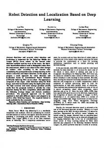
Fig. 1. KUKA omniRob platform (left) and the environment used for evaluation (right).
The key contribution of this paper is a thorough experimental evaluation of an integrated pose estimation and precise path planning/path execution system for an industrial mobile manipulation robot (see Fig. 1). The evaluation is performed using a high precision motion capture system that allows us to analyze the accuracy up to 0.1 mm at specific locations. The localization system itself is based on well-understood state-of-the-art approaches including Monte-Carlo localization, KLD sampling, and scan alignment procedures. We analyze the accuracy of the combined system and show that the platform can reliably navigate to desired target locations with a precision of a few millimeters neither requiring artificial markers nor wires embedded in the floor or any other external sensors for pose estimation. Our system relies only on laser rangefinders, a sensor modality which is anyway required for safety reasons in most countries as soon as robots share their workspace with human workers. We believe that our analysis of the localization and positioning accuracy of mobile robots is valuable for designing robotic applications in the industrial context, for example for transportation tasks, pick and place actions, docking maneuvers as well as other systems where pose accuracy is crucial. II. R ELATED W ORK Mobile robot localization is a well studied field in robotics and several approaches to localization have been proposed in the past [1], [2], [7], [10], [15], [19]. Probabilistic approaches have been successfully applied to localize robots with respect to a given map in a robust manner, often relying on techniques such as extended Kalman filters (EKF) [19], histogram filters [13] or particle filters, often referred to as Monte-Carlo localization (MCL) [8]. There exist also
approaches combining ideas of MCL and histogram-based methods [18]. Commonly used sensors for vehicle localization are cameras [1], [2], [10], [15], [22], RFID or wireless receivers estimating radio signal strength [11], [9], laser scanners [8], [17] or GPS receivers. Vision-based MCL was first introduced by Dellaert et al. [7]. Several image-based localization techniques have been proposed that work on panoramic images [1], [15], [20]. A localization accuracy between 0.4 m and 0.8 m is reported in [15] and around 1 m in [1]. Other localization techniques use perspective cameras and store a database of visual landmarks, for example using SIFT features. Se et al. [22] were the first to perform localization using SIFT descriptor matching but did not track the position of the robot over time. Elinas and Little [10] present a MCL-based system using stereo cameras and SIFT features whereas Bennewitz et al. [2] work with monocular cameras and do not require explicit data associations among features. Cho and Kim propose an EKF-based method for mobile robot localization using chirp-spread-spectrum ranging [6]. The approach measures the distances between a mobile robot and landmarks according to the time of flight of radio frequency signals. Localization has also been performed using wireless signals, for example, by Ferris et al. [11] and Duvallet and Tews [9]. Both exploit Gaussian Process regression for probabilistically modeling the signal strength. Quigley et al. [21] analyze the localization accuracy in unmodified environments using only inexpensive sensors such as those employed in smartphones. They report a sub-meter localization indoors, which is sufficient for most smartphonedriven applications but often not enough for robots operating in industrial settings. Laser rangefinders are a popular sensor for robotic applications, since they provide precise distances to obstacles and basically require no pre-processing of the sensor data itself. Especially in the industrial context, most mobile robots are equipped with laser scanners to perceive the environment, to avoid obstacles and to carry out emergency stops. Therefore, we only concentrate on laser-based localization in this work. For standard MCL with SICK laser scanners, position errors between 0.05 m and 0.2 m are reported in [8] and [25]. There exist more recent reports on EKF/UKF-based pose estimation errors for a Pioneer2 robot using SICK laser rangefinders where the error is around 0.25 m and 3.5 deg [17]—these errors appear to be rather large and their source is not really clear from our perspective. Brˇscˇ i´c and Hashimoto report errors below “0.1 m at all times, while being less than 0.05 m most of the times” in [3] for a similar hardware setup. These results are roughly comparable to the accuracy shown in [8], [25]. Already in 1998, Gutmann et al. [16] evaluated the localization quality of laser-based systems also considering scan matching to improve the localization accuracy. They report highly accurate results. It should be mentioned that given the evaluation possibilities at these times, scan matching has also been used for determining the ground truth estimates. The results presented in our paper put the evaluation on a more precise ground.
Relatively little can be found about comprehensive evaluations of the accuracy of localization systems as it is required for industrial mobile robots. Rather, most industrial systems still require environment modifications such as wires embedded in the floor or magnetic tape on the floor. The contribution of this paper is the analysis of an integrated laser-based localization and precise navigation system for solving tasks in industrial settings without requiring modifications of the environment. By combining Monte-Carlo localization with KLD sampling [12] and fine repositioning using scan alignment as proposed by Censi [4], we build a navigation system that can approach a target location with an accuracy of a few millimeters. Whereas similar combinations have been used in the past, for example in [16] or in the localization system of the robot navigation toolkit CARMEN, our approach additionally integrates the pose estimation system with precise path execution. It is based on the path execution system by Sprunk et al. [23] with the goal of arriving at designated target locations with high precision. The main contribution of this paper is thus the experimental evaluation. We analyze the accuracy of the combined localization and motion execution system. We show that a mobile platform designed for industrial applications (we used the KUKA omniRob platform) can approach a desired target location with a precision of a few millimeters without requiring any external landmarks or artificial markers, no wires embedded in the floor or any other external means for pose estimation. We believe that such results are essential and will finally pave the way for autonomous mobile robots in industrial settings. III. E VALUATED A PPROACH The deployment of a mobile robot in an industrial setting poses strict requirements for a localization system in terms of efficiency, accuracy and robustness. In this section, we describe how we modified the standard MCL algorithm to comply with these three requirements. A. Monte-Carlo Localization with KLD Sampling As a first step, we estimate the pose xt of the robot at time t applying the Monte-Carlo localization (MCL) proposed by [8], which recursively estimates the posterior about the robot’s pose as follows: p(xt | z1:t , u0:t−1 ) ∝ Z p(zt | xt ) p(xt | x0 , ut−1 )p(x0 | z1:t−1 , u0:t−2 ) dx0 . x0
Here, u0:t−1 is the sequence of motion commands executed by the robot and z0:t is the sequence of observations. The motion model p(xt | xt−1 , ut−1 ) denotes the probability that the robot ends up in state xt given it executes the motion command ut−1 in state xt−1 and the observation model p(zt | xt ) denotes the likelihood of making the observation zt given the robot’s pose xt . To represent p(xt | xt−1 , ut−1 ), we employ the odometry motion model and for p(zt | xt ), we use the likelihood field (also called beam endpoint model), both as defined in [24].
MCL uses a set of random samples also called particles to represent the belief of the robot about its state and updates the belief by sampling from the motion model when receiving odometry information. The particles are weighted according to the observation model whenever new observations are perceived. To optimize the performance of the MCL, we apply the KLD sampling [12] algorithm to adjust the number of particles online. KLD sampling adapts the number of particles by limiting the error introduced by the sample-based representation. The error is computed using the KullbackLeibler divergence between the sampled distribution and a discrete distribution computed over the whole map. Thus, particles are basically generated on demand. For example, during global localization or in areas where localization is difficult new particles are created while the system keeps the particle set small when tracking the robot’s pose. More details on the technical realization can be found in [12]. B. Scan Matching to Improve the Precision Due to the limited number of particles typically used and the relatively coarse resolution of the underlying grid map, the precision of the resulting pose estimate from MCL is not always sufficient for an industrial setting. To improve the accuracy of the pose estimates at the target destinations, we store local sensor measurements as reference observations in the map and use them for scan matching during runtime. We apply a variant of a scan matching routine based on the iterative closest/corresponding point (ICP) principle with a point-to-line metric [4]. It computes the relative position of the robot with respect to the position where the reference scans were taken. This has the advantage that the reference scans do not depend on the accuracy and resolution of the grid map used in MCL. It is important to note that the scan matching step is used as a post processing step using the MCL output as initial guess. The scan match result is not integrated back into the MCL estimate. C. Increasing Robustness It is well known that MCL is robust to small changes in the environment. To even deal with significant dynamics in the scene, for example caused by people walking by, one can mask those beams of a scan that are not well explained by the map when integrating over all particles [13]. Then, the weighting step of the filter considers only the remaining beams when computing the weight for each sample. Scan matching procedures itself are typically very accurate if the local minimum the approach found is also the global one. Thus, the property of robustness does not necessarily hold for the scan matcher and thus the final position that is provided by our localization system. We increased the robustness of the scan matcher in two ways. First, we eliminate outliers in the laser readings using a trimmed version in the ICP steps [5]. In trimmed ICP, the data points with the least likely correspondences between the scans are discarded when computing the transformation. This enables the scan matcher to tolerate a number of spurious
initial path, slow
optimized path, fast
Fig. 2. Trajectories before and after optimization using the approach by Sprunk et al. [23]. The generated trajectories account for constraints on velocities and accelerations.
readings, for example, caused by dynamic obstacles or slight modifications of the environment. Second, we exploit the redundancy of two laser rangefinders to account for potential failures. We perform two independent scan matching steps, one for each laser. We then compare the two solutions and discard them if they differ substantially from each other or from the MCL estimate. In case of inconsistencies, the system collects new scans and tries to match again, until a maximum number of iterations is reached. We found that this strategy is helpful in environments with high dynamics such as multiple people in the direct vicinity of the robot. D. Path Planning and Accurate Path Execution For planning the motions of the robot, we use the motion generation approach recently presented by Sprunk et al. [23] without modifications. This method generates smooth base trajectories for holonomic omnidirectional robots (a variant for differential-drive systems exists as well). The method takes as input a set of waypoints and a map of the environment to generate curvature continuous trajectories. Furthermore, it explicitly accounts for constraints on the velocity and acceleration of the vehicle which allows a feedback controller to track the generated trajectories with high precision. The approach starts from an initial trajectory created either from a sequence of given waypoints or from a traditional path planner such as A*. It then employs an anytime optimization of the shape of the trajectory with respect to a user-defined cost function, e.g., the time of travel. A schematic example of the optimization process is depicted in Fig. 2. Through regular replanning and smooth, continuous stitching of updated trajectories the method can react to unmapped obstacles [23]. IV. E XPERIMENTAL E VALUATION The evaluation of the integrated localization and motion planning system was done in the hall shown in Fig. 3 (left) which we equipped with a motion capture system of Motion Analysis Digital using 9 Raptor-E cameras. The motion capture system (mocap) allows us to accurately determine the pose of the robot operating in the environment and thus to evaluate the performance of the navigation system. As a robot, we used the KUKA omniRob system, a new omni-drive steered platform developed by KUKA and targeted to the industrial as well as the research market. By default, the robot is equipped with two SICK S300 laser rangefinders.
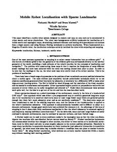
1m location 2 location 3
location 3 location 2
location 1
location 1
Fig. 3. Left: Evaluation site equipped with a motion capture system. Right: Grid map of the environment with 0.05 m resolution as used for Monte-Carlo localization. Also shown are the three target locations of the platform in front of the work benches.
The map for the localization system was built using a graph-based SLAM system [14]. For recording the map, the robot was manually steered through the environment. A. Task of the Robot For our evaluation, we selected a typical navigation task that needs to be performed in the industrial context. The task of the robot was to approach three different work benches and to position itself as accurately as possible in front of the work benches so that objects can be picked up or be delivered to the work place (without requiring further sensors for visual servoing or similar). In our setup, the robot had to repeatedly approach the three work benches depicted in Fig. 3 (left). Every time the robot stopped, the localization and the position accuracy of the platform were evaluated. The three reference positions in front of the work benches were taught in to the robot beforehand. This was done by moving the robot to the three individual locations and then recording the reference scans and MCL estimates. B. Calibration and Accuracy of the Motion Capture System The motion capture system provides 6D pose information of markers in the environment. The markers were attached to the robot to track its pose. As a first step, we calibrated the mocap system using its own setup and calibration procedure. Second, we attached markers to the floor to appropriately obtain the ground plane and so that all further considerations can be carried out in 2D. Third, we record the reference locations by moving the robot physically to the desired goal locations and recording the coordinates using the mocap. Even for a precise mocap system, one has to distinguish between the global and the local accuracy. We found that the poses provided by the mocap are not necessarily globally precise up to sub-millimeter accuracy. Locally, i.e., when returning to the same place again, the mocap provides submillimeter accuracy when the markers are standing still and one can average over multiple readings reported by the mocap (knowing that the markers do not move). To evaluate the local accuracy of the calibrated mocap system, we left the markers at the reference positions and covered the markers after recording them so that the mocap lost track although
the markers have not been moved in reality. After a while, we removed the covers and estimated the pose of the markers again. By comparing the obtained poses, we always found a position error of slightly below 0.1 mm. To verify that the mocap does not have any drift in its pose estimate, we also verified that the average positioning error of the robot does not shown any time-dependent systematic errors. We did not notice any systematic errors over time in any of our experiments. C. Evaluation Metric As our evaluation metric, we use the pose error of the robot relative to the taught-in locations. Here, we consider the error in the x, y-plane as well as the angular error (yaw). Throughout our experiments, we provide two different errors. First, the positioning error of the robot to determine how accurate the robot can position itself. This is the joint error of the localization and positioning system as a whole. Knowing about this error is, for example, essential for designing a docking station or a docking behavior. Second, we evaluate the error of the localization system alone, which tells us how accurately the robot can estimate its own pose. Thus, this error ignores possible limitations in the low-level controller or hardware of the platform that affect the motion execution. When computing the pose error of the robot, we always determine the error relative to a reference location and not based on a global map reference frame. This is done for three reasons. First, the mocap system is typically not globally precise up to millimeter accuracy. Second, computing the error with respect to a global map up to a millimeter is difficult since most maps build with today’s SLAM systems do not provide such an accuracy. Third, computing the error locally does not require to determine the coordinate transformation between the map of the robot and the mocap system. Depending on the map resolution, errors in the order of a few millimeters are very likely. Thus, we compute the error of the robot only as a relative error, computed with respect to previously taughtin reference locations. To teach in reference locations, we positioned the robot before the evaluation run in front of
[m]
[deg]
0.01
0.4
0.005
0.2
0
positioning error localization error
0 location 1
location 2
location 3
all places
location 1
location 2
location 3
all places
Fig. 4. Positioning (blue) and localization (red) error plotted for the tree different positions as well as for all places together. The boxes indicate the average error and the bars show the standard deviation (and not the standard error) to illustrate the distribution of the error in each setting. The cross indicates the maximum error that occurred during the experiments. Whereas the left plot shows the error in the x, y-plane, the right plot contains the angular error. The plots are created from an experiment in which the robot performed 390 positioning actions, executed in random order.
each work bench and recorded the current MCL estimate and reference scans for the scan matcher. Then, the task of the robot was to come back to exactly this location. As a result, the error between the desired and approached location can be measured with high precision. In our evaluation, we only considered the pose error when the robot was standing at the desired goal locations and not during the motion of the robot. This has two reasons. First, sub-millimeter accuracy can be obtained only when the markers are standing still and the poses are averaged over multiple readings. Second, when evaluating the robot’s pose while driving, a highly accurate time synchronization between the robot and the mocap is needed—otherwise, the results are imprecise. Such accurate time synchronization was not available between the realtime operating system inside the KUKA omniRob and the mocap. D. Accuracy in a Static Environment This experiment is designed to analyze the localization and positioning capabilities of the robot in a static environment. We set up and calibrated the mocap system as described above and then let the robot perform 390 tours to the different work benches shown in Fig. 3, which took approximately 3.5h. Whenever the robot reached its desired target location, we computed the translational and rotational error between the robot’s pose and the taught-in reference location. In addition to that, we analyzed the difference between the estimated position of the robot’s localization system and the one reported by the mocap. The reason why these two errors are different is the fact that the robot’s firmware does not execute small movements shorter than of 3 mm in distance. Fig. 4 depicts the results of these experiments. Whereas the left plot shows the translational error in the x, y-plane, the right plot shows the angular error. The boxes indicate the average error and the bars show the standard deviation to illustrate the distribution of the error. The cross indicates the maximum error that occurred throughout the experiments. As can be seen from the figure, the average localization error over all experiments is 3 mm/0.06 deg and the average positioning error, i.e., the final position of the platform, was 5 mm/0.15 deg. Note that even the maximum errors are small. The maximum localization error was 12 mm/0.3 deg and the maximum position error 15 mm/0.5 deg. To better illustrate the errors of our system, Fig. 5 depicts
positioning error at location 1 [m]
positioning error at location 3 [m] 0.005
0.005 0 0 −0.005 −0.005 −0.01 −0.005
0
0.005
−0.005
0
0.005
Fig. 5. Plots of the obtained positioning results at two different reference locations. Whereas the large red cross in the middle represents the desired target location, the blue crosses show the positions of the robot.
the positioning results obtained at two different reference locations. The large red cross in the middle represents the desired target location and the blue crosses show the positions approached by the robot. The plots summarize the results of approximately 250 positioning actions at the two reference locations. As can be seen, there are no significant outliers and the approached positions are roughly centered around the reference locations. In sum, our system allows a mobile robot to precisely localize itself and to approach a desired goal appropriately. For comparison, the estimates of the pure MCL localization were scatterred in a 0.06 m × 0.06 m area at each target location at a grid resolution of 0.05 m. E. Accuracy in a Dynamic Environment This experiment is designed to analyze the localization and positioning capabilities of the robot in a dynamic environment. Here, the focus was not on a complete rearrangement of the scene but on people walking close to the robot or objects that are additionally placed in the environment close to the reference locations. We performed three different experiments with different levels of dynamics. In the first experiment, three people were walking in the direct proximity of the robot and thus obstructing its laser range readings. In the second experiment, the number of people was increased to eight. Finally, in the third experiment, eight people as well as additional objects were placed in the direct proximity of the robot. We used three boards (0.8 m to 2 m) to shield and occlude relevant parts of the scene. The analysis of these experiments is depicted in Fig. 6. As can be seen, the localization and the position error increases
positioning error
localization error
[deg]
[m] 0.015
0.4 0.01 0.2 0.005 0
0 3 people 8 people
serious occlusions
3 people 8 people
serious occlusions
Fig. 6. Accuracy obtained in three experiments with dynamics in the environment. Again, the boxes depict the average error, the bars the standard deviation, and the crosses the maximum error that occurred in each setting. This plot only includes the successful localization steps, i.e., those in which the scan matcher did not report an error (see Sec. III-C).
compared to the static environment. The increase, however, is not substantially and is roughly characterized by a factor of two. The worst result we obtained was a position error of 17 mm and 0.53 deg. F. Robustness During all experiments in the static as well as in the dynamic setup, the Monte-Carlo localization approach never failed. It was always able to first globally find the robot’s pose and then track it reliably. In the static setup, we also did not observe any failures of the scan matching system. The correct mode was always found and the maximum localization error was 12 mm/0.3 deg as reported above. In the dynamic setup, the task was more difficult for the scan alignment procedure. As long as only people were blocking the laser scanners, the system worked flawlessly without a single failure. However, after heavily obstructing the scanner with up to 2 m long boards set up in a way to create ambiguous patterns given the environment structures (extending walls or creating the impression that walls are closer to the robot), the scan matching routine failed a few times. Here, failure means that the scan matching processes of the front or rear lasers provide results that are significantly different from each other or the MCL belief. If this occurs for two repeated trials, the robot reports an error, since it cannot fine-position itself due to the high obstructions. V. L ESSONS L EARNED Implementing and deploying a system that is able to work reliably for long-term operation is not an easy task. In this section, we discuss some of the lessons we learned during the development and the tests of the system. A. On the Importance of Parameters Complex systems like the one presented in this paper often have a lot of different parameters. It is well known that finding the right values for them is a task that should not be underestimated. We tried to keep the number of sensitive parameters to a minimum, and always tried to formulate them as entities that can be understood from the user perspective. The most sensitive parameter for MCL is the number of
particles. The optimal value is in general hard to determine, since it strongly depends on the size of the environment and is always a trade off between efficiency and success rate. With the use of KLD sampling, the system adapts the number of particles according to how well the sample distribution represents the real one. Although this looks like we increased the parameters from one (the number of samples) to two (the KLD error and the maximum number of particles), the new parameters do not really depend on the environment anymore but have a general meaning that depends on (a) the desired accuracy and (b) the computational resources that are available to the localization module. Using the scan matching routine to obtain the final pose estimates reduces the influence of other parameters of MCL as well. In particular, we found that the variances of both, the motion and the observation models, do not need a lot of tuning. Unless they are not set to unrealistically small values, the variances do not have a strong influence on the final results or on the convergence rate, but only on the speed of convergence. For the same reason, the resolution of the map is also not as important anymore as long as it is higher than the attraction area of the scan matching process (0.25 m in our current implementation). In our experiments, we set the grid map resolution to 0.05 m. B. On the Integration of MCL and Scan Matching Integrating a scan matching process on top of a localization algorithm poses some implementation issues that need to be addressed. A first question is the choice of the scan matching algorithm, since one can easily get lost in the large number of available methods. We found out, however, that what is really important is to choose which family of scan matching to use: grid-based or scan-based. Grid-based or correlative algorithms use an occupancy grid and match the current scan with a whole map by maximizing their correlation, while scan-based algorithms store a reference scan and try to find the transformation that maximizes the overlap of the points of the current scan with the reference one. There are advantages and disadvantages for both methods, and the choice depends on the application. Gridbased methods are preferable when a precise position is needed continuously and not only at reference positions. The accuracy, however, will be lower compared to scan-based approached and the scan alignment approach then depends on the map discretization and to some degree on the accuracy of the SLAM algorithm that was used to build the map. Scan-based methods provide a higher accuracy but can work reliably only if they have a reference scan taken from about the same position. In our case, we used a scan-based method for its higher precision and due to the requirement to localize precisely only in a set of predefined positions. A second question is when to run the scan matcher. Since we decide to use a scan-based method, we do not want to run it until the robot is close enough to the reference location. We decided to run it only if the estimated position from MCL is within the attraction area of the scan matcher, which we experimentally found to be approximately 0.25 m.
C. On the Use of Two Laser Rangefinders We used both laser rangefinders that are installed by default on the KUKA omniRob platform to increase the reliability and accuracy of the localization routine. We found some aspects to be important in the multi-sensor setting. Using two laser scanners as a unified sensor increases the convergence rate and the accuracy of MCL. Especially, if the environment looks ambiguous given only one sensor, the second scanner is likely to resolve the ambiguity. However, one needs to take into account that the sensors may partially observe the same area and these parts of the scan may not be considered as independent. We furthermore found that both, the time stamping for the two laser scanners and the odometry information has to be precise. Otherwise, it is difficult to align the two scans without systematic errors and this can affect the performance. Regarding the scan matching routine, however, we found that it is better to use the two lasers individually as this increases the robustness in the presence of dynamic obstacles. The problem is that there is not yet a robust solution to decide if the scan matching process ended up in a local minimum. Most scan matching implementations rely on thresholds defined on the scan matching score or likelihood functions and reject solutions below that threshold. Using the two lasers individually allows us to check for consensus between them and discard the scan matching estimates if there is no consensus. In industrial settings, safety is a significant issue and if the desired accuracy cannot be achieved it is important to signal this information to the user or supervisor. VI. C ONCLUSIONS In this paper, we presented an analysis that thoroughly evaluates the accuracy of a mobile robot localization and positioning system using an highly precise motion capture system. The localization system is built upon standard components that are well understood in robotics, namely MonteCarlo localization, KLD sampling, and scan matching. Our analysis is targeted to developers of robotic applications in which pose accuracy matters such as in industrial applications. We are able to show that it is possible to achieve a localization and positioning accuracy of a few millimeters at taught-in reference locations. Even in environments with significant dynamics, the error of the described system is small and typically around 7 mm/0.15 deg and never exceeded 17 mm/0.53 deg in any of our experiments. This accuracy allows for creating robotic applications that require high precision, for example, for docking maneuvers or mobile manipulation tasks. R EFERENCES [1] H. Andreasson, A. Treptow, and T. Duckett. Localization for mobile robots using panoramic vision, local features and particle filter. In Proc. of the IEEE Int. Conf. on Robotics & Automation (ICRA), 2005. [2] M. Bennewitz, C. Stachniss, W. Burgard, and S. Behnke. Metric localization with scale-invariant visual features using a single perspective camera. In European Robotics Symposium 2006, volume 22 of STAR Springer tracts in advanced robotics, pages 143–157, 2006.
[3] D. Brˇscˇ i´c and H. Hashimoto. Comparison of robot localization methods using distributed and onboard laser range finders. In IEEE/ASME Int. Conf. on Advanced Intelligent Mechatronics, 2008. [4] A. Censi. An ICP variant using a point-to-line metric. In Proc. of the IEEE Int. Conf. on Robotics & Automation (ICRA), Pasadena, CA, May 2008. [5] D. Chetverikov, D. Svirko, D. Stepanov, and P. Krsek. The trimmed iterative closest point algorithm. In Proc. of the Int. Conf. on Pattern Recognition, 2002. [6] H. Cho and S.W. Kim. Mobile robot localization using biased chirpspread-spectrum ranging. IEEE Trans. on Industrial Elect., 57, 2010. [7] F. Dellaert, W. Burgard, D. Fox, and S. Thrun. Using the Condensation algorithm for robust, vision-based mobile robot localization. In Proc. of the IEEE Conf. on Computer Vision and Pattern Recognition (CVPR), 1999. [8] F. Dellaert, D. Fox, W. Burgard, and S. Thrun. Monte Carlo localization for mobile robots. In Proc. of the IEEE Int. Conf. on Robotics & Automation (ICRA), 1999. [9] F. Duvallet and A. Tews. Wifi position estimation in industrial environments using Gaussian processes. In Proc. of the IEEE/RSJ Int. Conf. on Intelligent Robots and Systems (IROS), 2008. [10] P. Elinas and J.J. Little. σMCL: Monte-Carlo localization for mobile robots with stereo vision. In Proc. of Robotics: Science and Systems (RSS), 2005. [11] B. Ferris, D. Haehnel, and D. Fox. Gaussian processes for signal strength-based location estimation. In Proc. of Robotics: Science and Systems (RSS), 2005. [12] D. Fox. Adapting the sample size in particle filters through kldsampling. Int. Journal of Robotics Research, 22, 2003. [13] D. Fox, W. Burgard, and S. Thrun. Markov localization for mobile robots in dynamic environments. Journal on Artificial Intelligence Reserach (JAIR), 11, 1999. [14] G. Grisetti, R. K¨ummerle, C. Stachniss, U. Frese, and C. Hertzberg. Hierarchical optimization on manifolds for online 2d and 3d mapping. In Proc. of the IEEE Int. Conf. on Robotics & Automation (ICRA), 2010. [15] H.-M. Gross, A. K¨oning, C. Schr¨oter, and H.-J. B¨ohme. Omnivisionbased probabilistic self-localization for a mobile shopping assistant continued. In Proc. of the IEEE/RSJ Int. Conf. on Intelligent Robots and Systems (IROS), 2003. [16] J.-S. Gutmann, W. Burgard, D. Fox, and K. Konolige. An experimental comparison of localization methods. In Proc. of the IEEE/RSJ Int. Conf. on Intelligent Robots and Systems (IROS), 1998. [17] E. Ivanjko, A. Kitanov, and I. Petrovi´c. Robot Localization and Map Building, chapter Model based Kalman Filter Mobile Robot SelfLocalization, pages 59–89. In-Tech, Vukovar, Croatia, 2010. [18] P. Jensfelt, D. Austin, O. Wijk, and M. Andersonn. Feature based condensation for mobile robot localization. In Proc. of the IEEE Int. Conf. on Robotics & Automation (ICRA), 2000. [19] J.J. Leonard and H.F. Durrant-Whyte. Mobile robot localization by tracking geometric beacons. IEEE Transactions on Robotics and Automation, 7(4):376–382, 1991. [20] E. Menegatti, M. Zoccarato, E. Pagello, and H. Ishiguro. Image-based Monte-Carlo localisation with omnidirectional images. Robotics & Autonomous Systems, 48(1):17–30, 2004. [21] M. Quigley, D. Stavens, A. Coates, and S. Thrun. Sub-meter indoor localization in unmodified environments with inexpensive sensors. In Proc. of the IEEE/RSJ Int. Conf. on Intelligent Robots and Systems (IROS), 2010. [22] S. Se, D.G. Lowe, and J.J. Little. Global localization using distinctive visual features. In Proc. of the IEEE/RSJ Int. Conf. on Intelligent Robots and Systems (IROS), 2002. [23] C. Sprunk, B. Lau, P. Pfaff, and W. Burgard. Online generation of kinodynamic trajectories for non-circular omnidirectional robots. In Proc. of the IEEE Int. Conf. on Robotics & Automation (ICRA), 2011. [24] S. Thrun, W. Burgard, and D. Fox. Probabilistic Robotics. MIT Press, Cambridge, MA, USA, 2005. [25] S. Thrun, D. Fox, W. Burgard, and F. Dellaert. Robust Monte Carlo localization for mobile robots. Artificial Intelligence, 128, 2001.